218 HYLAB 5 Luffing Attachment Dimensions - Link-Belt ...
218 HYLAB 5 Luffing Attachment Dimensions - Link-Belt ...
218 HYLAB 5 Luffing Attachment Dimensions - Link-Belt ...

Create successful ePaper yourself
Turn your PDF publications into a flip-book with our unique Google optimized e-Paper software.
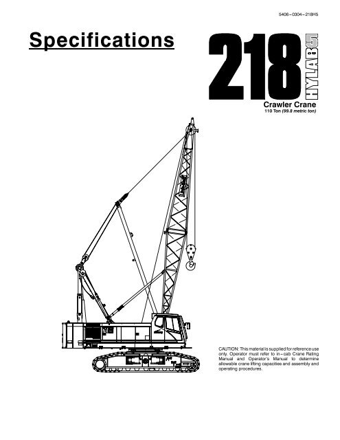
Specifications<br />
5406---0304---<strong>218</strong>H5<br />
Crawler Crane<br />
110 Ton (99.8 metric ton)<br />
CAUTION: This material is supplied for reference use<br />
only. Operator must refer to in---cab Crane Rating<br />
Manual and Operator’s Manual to determine<br />
allowable crane lifting capacities and assembly and<br />
operating procedures.<br />
1
5406---0304---<strong>218</strong>H5
5406---0304---<strong>218</strong>H5<br />
20’ 3.8”<br />
(6.2m)<br />
4’ 7.8”<br />
(1.38m)<br />
46.63”<br />
(1.18m)<br />
9’ 6.8”<br />
(2.9m)<br />
16’ 5”<br />
(5.00m)<br />
17’ 11”<br />
(5.46m)<br />
26’ 9.2”<br />
(6.21m)<br />
20’ 10.5”<br />
(6.36m)<br />
General <strong>Dimensions</strong> English Metric<br />
Tailswing Of Counterweight “A” 16’ 2.7” 4.9m<br />
Maximum Live Mast Working Height 34’ 6” 10.52m<br />
Boom Foot Pin Diameter 3.5” 8.89cm<br />
39.37”<br />
(1.00m)<br />
82_<br />
Boom<br />
Angle<br />
40’ 0” (12.2m)<br />
Basic Boom<br />
7’ 6”<br />
(2.29m)<br />
11’ 5.3”<br />
(3.48m)<br />
36”<br />
(0.91m)<br />
* Nominal capacity rating may vary based on specification. Tube boom capacity with 4--sheave head machinery is 110--ton<br />
(99.8mt). Tube boom capacity with optional 3--sheave head machinery and “CASARt” rope is 100--ton (90.7mt). Angle boom<br />
capacity is 100--ton (90.7mt).<br />
14’ 2.8”<br />
(4.3m)<br />
11’ 8”<br />
(3.6m)<br />
19.13”<br />
(0.48m)<br />
17’ 6” (5.33m)<br />
Extended (Shown)<br />
11’ 11.8” (3.65m)<br />
Retracted<br />
1
2 5406---0304---<strong>218</strong>H5<br />
Transportation Weights<br />
Base Crane: Rigid Boom Backstops, 77 gal (291L) Of Fuel, Catwalks (Front And Right Side), Lower Jacking System, 26’ (7.9m) LiveMast,<br />
Bridle & Spreader Bar, 10---part Boom Hoist Reeving, 870’ (265.18m) Of Type “DB” Front Hoist Rope, 650’ (198.12m) OfType“RB”RearHoist<br />
Rope.<br />
Item Description<br />
Base Crane 74,030 (33 579) 1<br />
Gross Weight Transport Loads<br />
lb (kg) #1 #2 #3 #4 #5<br />
Add “A” Counterweight 25,350 (11 499) 1<br />
Add “B” Counterweight 25,350 (11 499) 1<br />
Add Side Frame (2 Required) 23,561 (10 687) 1 1<br />
Add Hydraulic Third Drum Without Rope 1,850 (839)<br />
Add 20’ (6.1m) TubeBaseSection 1,991 (903) 1<br />
Add 20’ (6.1m) TubeTopSection 3,690 (1 674) 1<br />
Add 10’ (3.05m) Tube Extension With Pins And Pendants 844 (383) 1<br />
Add 20’ (6.1m) Tube Extension With Pins And Pendants 1,353 (614) 1 1<br />
Add 30’ (9.14m) Tube Extension With Pins and Pendants 1,894 (859) 1 1<br />
Add 40’ (12.19m) Tube Extension With Pins And Pendants 2,357 (1 069) 1 1<br />
Add 20’ (6.1m) AngleBaseSection 2,695 (1 222)<br />
Add 20’ (6.1m) Angle Top Section With 4 Lifting Sheaves 3,146 (1 427)<br />
Add 20’ (6.1m) Angle Top Section With 3 Lifting Sheaves 3,139 (1 424)<br />
Add 20’ (6.1m) Angle Top Section With 2 Lifting Sheaves 3,037 (1 378)<br />
Add 10’ (3.05m) Angle Section With Pins And Pendants 1,047 (475)<br />
Add 20’ (6.1m) Angle Extension With Pins And Pendants 1,696 (769)<br />
Add 30’ (9.1m) Angle Extension With Pins And Pendants 2,448 (1 110)<br />
Add Bridle And Spreader Bar Only (No Live Mast) 885 (401)<br />
Add Quick Draw Assembly 623 (283) 1<br />
Add Tagline Winder With Rope 1,040 (472)<br />
Add Fairleader 500 (227)<br />
Add 30’ (9.1m) Tube Jib 1,965 (891) 1<br />
Add 15’ (4.6m) Tube Jib Extension 290 (132) 3<br />
Add 5’ (1.5m) Auxiliary Tip Extension 640 (290)<br />
AddPileDriverLeadAdaptor 198 (90)<br />
Add Holding Rope --- 1” X 220’ Type “DB” 352 (160)<br />
Add Closing Rope --- 1” X 165’ Type “DB” 444 (201)<br />
Add Inhaul Rope --- 1” X 80’ Type “M” 185 (84)<br />
Add Hoist Rope --- 1” X 700’ Type “DB” 1,295 (587)<br />
Add Hoist Rope --- 1” X 700’ Type “CC” 1,421 (645)<br />
Add Jib Wire Rope --- 1” X 700’ Type “DB” 1,295 (597)<br />
Add 3rd Drum Wire Rope --- 0.75” X 550’ Type “DB” 572 (259)<br />
Add Auxiliary Lifting Bail 196 (89)<br />
Add 15 ---ton (13.6mt) Hook Ball --- Non Swivel 750 (340) 1<br />
Add 15 ---ton (13.6mt) Hook Ball --- Swivel 760 (345)<br />
Add 110---ton (100mt) 4 Sheave Hook Block 2,946 (1 336) 1<br />
Remove Front Hoist Rope --- 1” X 870’ Type “DB” ---1,610 ( ---730)<br />
Remove Jib Wire Rope --- 1” X 650’ Type “RB” ---1,300 ( ---590)<br />
Remove 26’ (7.9m) Live Mast W/ Bridle And Spreader Bar ---2,949 ( ---1 338)<br />
Remove 50 gal (190L) OfFuel ---362 ( ---164)<br />
Approximate Total Shipping Weight<br />
lb 77,488 26,808 26,808 35,092 30,542<br />
kg 35 148 12 160 12 160 15 918 13 854<br />
Notes:<br />
Estimated weights vary by ± 2%. Numbers in the load columns (numbers 1---5) represent quantities.<br />
Estimated transport loads assume the load out consist of 230’ (70.1m) of tube boom and 75’ (22.86m) of jib with full counterweight.<br />
Support loads were targeted at 45,000 lb (20 412kg), 8’6”(2.6m) wide, 48’ (14.6m) long, and 13’ 6” (4.1m) high using a drop deck trailer. This<br />
may vary depending on state laws, empty truck/trailer weights, and style of trailer.
5406---0304---<strong>218</strong>H5<br />
Transport Drawings<br />
36”<br />
(0.9m)<br />
4’ 6”<br />
(1.38m)<br />
11’ 8” (3.6m)<br />
Cab Width<br />
11’ 11.8”<br />
(3.65m)<br />
Retracted<br />
11’ 11”<br />
(3.63m)<br />
Carbody<br />
Upper & Carbody Shipping Weight<br />
Without catwalks, fuel, live mast, backstops,<br />
wire rope, bail, bridle, or side frames<br />
65,343 lb (29 639kg)<br />
24.3”<br />
(0.62m)<br />
“A” Upper Counterweight<br />
25,350 lb (11 499kg)<br />
20’ 10.5”<br />
(6.36m)<br />
Side Frames w/ 36” (0.9m) Shoes<br />
23,561 lb (10 687kg) --- each<br />
Front Mounted Third Drum<br />
1,850 lb (839kg) --- w/o Rope<br />
24.3”<br />
(0.62m)<br />
“B” Upper Counterweight<br />
25,350 lb (11 499kg)<br />
Working Weights<br />
20’ 1.2”<br />
(6.13m)<br />
26’ 10”<br />
(8.18m)<br />
2’ 6”<br />
(0.8m)<br />
11’ 2” (3.4m)<br />
22’ 7.9”<br />
(6.90m)<br />
Transport Weight<br />
Rope on both drums, backstops, catwalks, and full tank of fuel<br />
121,152 lb (54 954kg)<br />
7’ 7”<br />
(2.31m)<br />
12’ 7.5”<br />
(3.85m)<br />
21’ 2” (6.45m) 20’ 6” (6.25m)<br />
20’ (6.1m)TopSection<br />
Tube: 3,690 lb (1 674kg)<br />
Angle: 3,146 lb (1 427kg)<br />
59”<br />
(1.5m)<br />
10’ 6.5”<br />
(3.21m)<br />
15’ 6.4”<br />
(4.73m)<br />
Extended<br />
Based on basic crane including Mitsubishi 6D24-TLA2H diesel engine, turntable bearing, independent hydraulic<br />
powered drums, boom hoist limiting device, independent hydraulic swing and travel, counterweight, swing brake,<br />
drum rotation indicators, and crawler lower with 36” (0.91m) wide track shoes, sealed track rollers, catwalks, hydraulic<br />
boom foot pin removal, plus the following:<br />
20’ 10.5”<br />
(6.36m)<br />
54”<br />
(1.37m)<br />
31’ 1” (9.5m)<br />
30’ (9.1m) Basic Jib Assembly<br />
Tube: 1,965 lb (891kg)<br />
16”<br />
(0.41m)<br />
42”<br />
(1.07m)<br />
12’ 4”<br />
(3.76m)<br />
4’ 6”<br />
(1.37m)<br />
Upper & Carbody Shipping Weight<br />
Rope on both drums, backstops, catwalks, and full tank of fuel<br />
76,865 lb (34 865kg)<br />
20’ (6.1m)BaseSection<br />
Tube: 1,991 lb (903kg)<br />
Angle: 2,695 lb (1 222kg)<br />
Carbody Jack minimum and<br />
maximum heights<br />
5’ 0”<br />
(1.52m)<br />
9.12’<br />
(2.78m)<br />
11’ 5.3”<br />
(3.48m)<br />
9’ 6”<br />
(2.90m)<br />
36.6”<br />
(0.92m)<br />
4’ 4”<br />
(1.32m)<br />
Ctwt “A” Ctwt “AB”<br />
lb kg lb kg<br />
Liftingg crane - includes 40’ ( (12.19m) ) basic tubular boom, 26’ (7.92m) ( ) live mast, 870’ ( (265.18m) ) of 1” (25.4mm) ( )<br />
diameter wire rope rope, 550’ (167 (167.6m) 6m) of 3/4” (19 (19.1mm) 1mm) diameter boom hoist rope rope, 110 110-ton ton (99 (99.8mt) 8mt) hook block block, and<br />
basic pendants.<br />
153 153,829 829 69 776 179 179,179 179 81 274<br />
Ground Bearing Pressure<br />
psi<br />
kg/cm<br />
9.58 11.16<br />
2 0.67 0.78<br />
3
4 5406---0304---<strong>218</strong>H5<br />
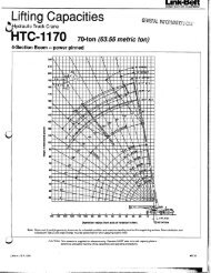
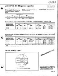
<strong>218</strong> <strong>HYLAB</strong> 5 <strong>Luffing</strong><br />
<strong>Attachment</strong> <strong>Dimensions</strong><br />
<strong>Luffing</strong> Boom “A”<br />
<strong>Luffing</strong> Jib “B”<br />
Minimum Maximum Minimum Maximum<br />
80’ (24.38m) 140’ (42.67m) 50’ (15.24m) 140’ (42.67m)<br />
150’ (45.72m) 80’ (24.38m) 100’ (30.48m)<br />
B<br />
A<br />
9’ 3”<br />
(2.82m)<br />
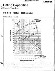
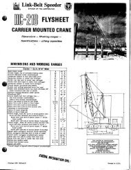
<strong>218</strong> <strong>HYLAB</strong> 5 <strong>Luffing</strong> <strong>Attachment</strong> Transport<br />
<strong>Luffing</strong> Shipping Module #1: 7,214 lb (3 272 kg)<br />
<strong>Luffing</strong> jib base section, luffing boom top section and<br />
the front and rear fan post.<br />
13”<br />
(0.33m)<br />
<strong>Luffing</strong> Shipping Module #2: 6,699 lb (3 039 kg)<br />
<strong>Luffing</strong> jib peak assembly with nose wheel, 30’ section (two<br />
each), 20’ section (one each), 10’ section (two each), 25 -ton<br />
hook block and 15 -ton hook ball.<br />
10’ 11”<br />
(3.33m)<br />
58”<br />
(1.47m)<br />
12’<br />
(3.66m)<br />
29’ 3.25”<br />
(8.92m)<br />
25” (0.63m)<br />
48’<br />
(14.63m)<br />
CG<br />
15’ 7.5”<br />
(4.76m)<br />
36’<br />
(10.97m)<br />
48’<br />
(14.63m)<br />
10’ 2.75”<br />
(3.12m)<br />
14’ 4.25”<br />
(4.38m)<br />
15--ton Hook Ball<br />
25--ton, 2--sheave<br />
Hook Block<br />
40”<br />
(1.02m)
5406---0304---<strong>218</strong>H5<br />
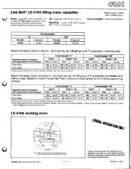
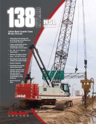
<strong>218</strong> <strong>HYLAB</strong> 5 <strong>Luffing</strong><br />
<strong>Attachment</strong> Nomenclature<br />
1<br />
37<br />
2<br />
36<br />
35<br />
1. <strong>Luffing</strong> Jib Nose Wheel<br />
2. <strong>Luffing</strong> Jib Head Sheaves<br />
3. <strong>Luffing</strong> Jib Pendants<br />
4. <strong>Luffing</strong> Jib Pendant Spreader Bar<br />
5. Backstop Targets<br />
6. <strong>Luffing</strong> Jib Backstops<br />
7. Front Fan Post<br />
8. Upper <strong>Link</strong><br />
9. Lower <strong>Link</strong><br />
10. Rear Fan Post<br />
11. Top Section Idler Sheaves<br />
12. Pendant Deflector Sheaves<br />
13. Tensiometer(s)<br />
14. Fan Post Pendants<br />
15. <strong>Luffing</strong> Jib Hoist Bridle<br />
16. Bridle Guide Assembly<br />
17. <strong>Luffing</strong> Jib Hoist Rope<br />
18. <strong>Luffing</strong> Jib Hoist Reeving<br />
19. <strong>Luffing</strong> Jib Bail<br />
3<br />
4<br />
34<br />
5<br />
32<br />
20. <strong>Luffing</strong> Boom Pendants<br />
21. <strong>Luffing</strong> Boom Live Mast<br />
22. <strong>Luffing</strong> Boom Backstops<br />
23. <strong>Luffing</strong> Boom Hoist Bail<br />
24. <strong>Luffing</strong> Boom Hoist Rope<br />
25. Gantry<br />
27<br />
26. “AB” Upper CTWT<br />
27. 20’ (6.1m) <strong>Luffing</strong> Boom Base Section<br />
28. 5’ (1.5m) <strong>Luffing</strong> Boom Bail Anchor Section<br />
29. Latch System<br />
30. <strong>Luffing</strong> Boom Extensions<br />
31. 5’ (1.5m) <strong>Luffing</strong> Boom Top Section<br />
32. Top Section Auxiliary Sheaves<br />
33. 20’ (6.1m) <strong>Luffing</strong> Jib Base Section<br />
34. <strong>Luffing</strong> Jib Extensions<br />
35. 20’ (6.1m) <strong>Luffing</strong> Jib Tip Section<br />
36. Hook Block<br />
37. <strong>Luffing</strong> Jib Load Hoist Rope<br />
6<br />
33<br />
7<br />
30<br />
29<br />
28<br />
31<br />
8 9 10<br />
11<br />
12<br />
15<br />
16<br />
17<br />
18<br />
14<br />
13<br />
19<br />
20<br />
21<br />
22<br />
23<br />
24<br />
25<br />
26<br />
5
6 5406---0304---<strong>218</strong>H5<br />
<strong>Attachment</strong> Options<br />
J 40’ - 230’ Tubular<br />
Boom (12.19 - 70.1m)<br />
Basic Boom -- 40’ (12.19m) two--piece design<br />
that utilizes a 20’ (6.10m) base section<br />
and a 20’ (6.10m) open throat top section<br />
with in--line connecting pins on 60” (1.52m)<br />
wide and 50” (1.27m) deep centers.<br />
S Boom foot on 61” (1.55m) center<br />
S 3” (76.2mm) diameter chords<br />
S Lugs on base section to attach<br />
carrying links<br />
S Skywalk platform<br />
S Deflector roller on top section<br />
S Permanent skid pads mounted on top<br />
section to protect head machinery<br />
S Four 21” (0.53m) root diameter steel<br />
sheaves mounted on sealed anti-friction<br />
bearings<br />
S Tip extension and jib connecting lugs<br />
on top section<br />
S Mechanical boom angle indicator<br />
Optional --- “Quick Drawt” handling<br />
system that mounts in the boom base to<br />
allow loading/unloading of a counterweight,<br />
a side frame or a boom<br />
section onto transport trailers.<br />
Tube Boom Extensions --- The following<br />
table provides the lengths available and the<br />
suggested quantity to obtain maximum<br />
boom in 10’ (3.05m) increments. Midpoint<br />
pendant connections are required at 100’<br />
(30.5m) for boom lengths 210’ (64.0m) and<br />
longer.<br />
Tube boom<br />
extensions<br />
Quantity for max<br />
boom<br />
10’ (3.05m) 1<br />
20’ (6.10m) 2<br />
30’ (9.14m) 2<br />
40’ (12.19m) 2<br />
S Deflector roller on top of each extension<br />
S Appropriate length pendants<br />
S Maximum tube boom tip height of 235’<br />
(71.63m)<br />
J 40’ -150’ Angle Boom<br />
(12.19 - 45.72m)<br />
Basic Angle Boom -- 40’ (12.2m) two--piece<br />
design that utilizes a 20’ (6.10m) base section<br />
and a 20’ (6.10m) open throat top section<br />
with in--line connecting pins. Boom extensions<br />
are 48” (1.22m) wide and 48”<br />
(1.22m) deep at outside<br />
dimensions of angles.<br />
S Boom foot on 61” (1.55m) center<br />
S 4” X 4” X 0.38” (101.6 x 101.6 x 9.5mm)<br />
angle chords<br />
S Lugs on base section to attach<br />
carrying links<br />
S Skywalk platform<br />
S Deflector roller on top section<br />
S Rigid sheave guards<br />
S Four 18” (0.46m) root diameter steel<br />
sheaves mounted on sealed antifriction<br />
bearings<br />
S Tip extension and jib connecting lugs on<br />
top section<br />
S Mechanical boom angle indicator<br />
Optional --- Three sheave head machinery<br />
for clam applications or two wide mouth<br />
sheaves for dragline applications.<br />
S Three sheave lift crane head machinery<br />
instead of standard (when used with<br />
“CASARt Stratoplast” rope) offers<br />
maximum capacity of 100--ton (90mt).<br />
Angle Boom Extensions -- The following<br />
table provides the lengths available and the<br />
suggested quantity to obtain maximum<br />
boom in 10’ (3.05m) increments. Midpoint<br />
pendant connections are not required.<br />
Angle boom<br />
extensions<br />
Quantity for max<br />
boom<br />
10’ (3.05m) 1<br />
20’ (6.10m) 2<br />
30’ (9.14m) 2<br />
S Deflector roller on top of each extension<br />
S Appropriate length pendants<br />
S Maximum angle boom tip height of 156’<br />
(47.56m)<br />
J 30’ - 75’ Tubular Jib<br />
(9.14- 22.86m)<br />
Basic Tube Jib -- 30’ (9.14m) two--piece design<br />
that utilizes a 15’ (4.57m) base section<br />
and a 15’ (4.57m) top section with in--line<br />
connecting pins on 32”<br />
(0.81m) wide and 24” (0.61m) deep centers.<br />
S 2” (50.8mm) diameter tubular chords<br />
S One 18.5” (0.47m) root diameter steel<br />
sheave mounted on sealed anti-friction<br />
bearings.<br />
S 15’ (4.6m) jib extensions provide jib<br />
lengths at 45’ (13.76m), 60’ (18.3m), and<br />
75’ (22.86m) for tube boom. Angle boom<br />
is limited to 60’ (18.29m).<br />
S Jib offset angles at 5˚, 15˚, and 25˚<br />
S Maximum tip height of tube boom + jib is<br />
269.5’ (82.14m).<br />
S Maximum tip height angle boom + jib is<br />
215’ (65.57m).<br />
J Auxiliary 5’ Tip<br />
Extension (1.5m)<br />
Designed to use in place of jib to provide<br />
clearance between working hoist lines. The<br />
extension is equipped with two nylon 18”<br />
(0.46m) root diameter sheaves mounted on<br />
sealed anti--friction bearings. Maximum capacityis9--ton(8.16mt).<br />
J 50’ - 140’ (15.24 -<br />
42.67m) <strong>Luffing</strong> Jib<br />
Basic <strong>Luffing</strong> Jib -- 50’ (15.24m) four--piece<br />
design utilizes a 20’ (6.10m) base section,<br />
10’ (3.05m) extension, 20’ (6.10m) top section<br />
with in--line connecting pins and 5’<br />
(1.5m) luffing boom top section. <strong>Luffing</strong> jib<br />
extensions are 39” (0.99m) wide and 48”<br />
(1.22m) deep at the centers.<br />
S 25--ton (22.68mt) maximum capacity<br />
S Working lengths of 50’ (15.24m) to 140’<br />
(42.67m)<br />
S Brackets on base section to attach fan-post<br />
transport links<br />
S Two steel 22.5” (0.57m) diameter luffing<br />
jib head sheaves<br />
S Two polyamide 21.25” (0.54m) diameter<br />
luffing boom auxiliary head sheaves<br />
S Pin--on nose wheel<br />
S Eight--part luffing jib hoist.<br />
S 1.25” (31.75mm) diameter type “N”<br />
pendants<br />
S Anemometer with in--cab display<br />
<strong>Luffing</strong> Jib Extensions -- The following<br />
table provides the lengths available and the<br />
suggested quantity to obtain the maximum<br />
luffing jib in 10’ (3.05m) increments. Midpoint<br />
pendants are not required.<br />
<strong>Luffing</strong> jib<br />
extensions<br />
Quantity for<br />
max boom<br />
10’ (3.05m) 1<br />
20’ (6.10m) 1<br />
30’ (9.14m) 2<br />
S Deflector roller on top of each extension<br />
S Appropriate length pendants<br />
S Max. luffing jib tip height is 283’ (86.26m).<br />
J <strong>Luffing</strong> Boom<br />
S Common base and extensions as open<br />
throat boom (HP boom only)<br />
S 5’ (1.5m) luffing extension required for<br />
bail anchor.<br />
S Working angles of 90˚, 85˚, 80˚, 75˚,<br />
70˚, and 65˚<br />
S Working lengths of 80’ (24.38m) to 140’<br />
(42.67m) with luffing jib combinations up<br />
to 140’ (42.67m) .<br />
S Maximum luffing boom length 150’<br />
(45.72m) with luffing jib combinations of<br />
80’ (24.38m), 90’ (27.43m), and 100’<br />
(30.48m) only.<br />
S 1.38” (34.92mm) diameter type “N” pendants;<br />
same as open throat boom.
5406---0304---<strong>218</strong>H5<br />
<strong>Luffing</strong> Boom Extensions -- The following<br />
table provides the lengths available and the<br />
suggested quantity to obtain the maximum<br />
luffing boom in 10’ (3.05m) increments. Midpoint<br />
pendants are not required.<br />
<strong>Luffing</strong> boom<br />
extensions<br />
Quantity for max<br />
boom<br />
10’ (3.05m) 1<br />
20’ (6.10m) 2<br />
30’ (9.14m) 1<br />
40’ (12.19m) 1<br />
Note: “HP” type boom must be used.<br />
S Rear hoist drum becomes luffing jib hoist<br />
S Optional third drum provides second<br />
working hoist line, if required.<br />
Revolving Upper Structure<br />
J Frame<br />
All welded steel frame with precision<br />
machined surfaces for mating parts.<br />
J Engine<br />
Mitsubishi 6D24--TLA2L with oil filter, oil cooler,<br />
air cleaner, fuel filter, water separator, tachometer,<br />
and electrical shutdown.<br />
Number of cylinders 6<br />
Bore and stroke -- in.<br />
(mm)<br />
5.12 x 5.91<br />
(130 x 150)<br />
Piston displacement -- in3 (L) 729<br />
(11.95)<br />
Engine rpm at full load speed 2,000<br />
Hi--idle rpm 2,200<br />
Gross hp (kw) 266 (198)<br />
Peak torque -- ft lb (joule) 870 (1179)<br />
Peak torque -- rpm 1,400<br />
Electrical system 24 volt<br />
Batteries 2--12 volt<br />
Approximate fuel consumption gal/hr (L/hr)<br />
100% hp 13.84 (52.40)<br />
75% hp 10.38 (39.29)<br />
50% hp 6.92 (26.19)<br />
25% hp 3.46 (13.10)<br />
J Hydraulic System<br />
Specifications<br />
Hydraulic Pumps -- The pump arrangement<br />
is designed to provide hydraulically powered<br />
functions allowing positive, precise control<br />
with independent or simultaneous operation<br />
of all crane functions.<br />
S Two variable displacement pumps operating<br />
at 4,550 psi (319kg/cm 2 ) and 83 gal/<br />
min (315L/min) powers load hoist drums,<br />
boom hoist drum, optional third drum, and<br />
travel.<br />
S One fixed displacement gear type pump<br />
operating at 2,985 psi (210kg/cm 2 ) and<br />
29.6 gal/min (112L/min) powers the swing<br />
motors and side frame retract cylinders.<br />
S One fixed displacement gear type pump<br />
operating at 2,985 psi (210kg/cm 2 ) and<br />
S Designed for self--assembly<br />
S <strong>Luffing</strong> jib hoist bridle and bail can remain<br />
reeved for crane transport<br />
S Job site mobility with attachment<br />
S Rolled out or rolled under erection<br />
methods<br />
S Compact transport module.<br />
J Boom Hoist System<br />
Designed to lift off maximum boom or maximum<br />
boom plus jib unassisted.<br />
Operates up to a maximum boom angle of<br />
82˚ for conventional boom and 90˚ for luffing<br />
boom. Boom hoist limit system limits<br />
maximum boom angle operation.<br />
S Retractable gantry frame and<br />
33.3 gal/min (126L/min) powers the swing<br />
motors.<br />
S One fixed displacement gear type pump<br />
operating at 2,985 psi (210kg/cm 2 ) and<br />
10.8 gal/min (41L/min) powers the pilot<br />
control system, clutches, brakes, counterweight<br />
cylinders, and pump controls.<br />
S One fixed displacement gear type pump<br />
operating at 1,420 psi (100kg/cm 2 ) and 8.1<br />
gal/min (31L/min) powers the oil cooler<br />
fan.<br />
Pump Control (“Fine Inching”) mode --<br />
Special pump setting, selectable from operator’s<br />
cab, that allows very slow movements<br />
of load hoist drums, boom hoist drum, and<br />
travel for precision work.<br />
Hydraulic Reservoir -- 53 gal (201L),<br />
equipped with sight level gauge. Diffusers<br />
built in for deaeriation.<br />
Filtration -- One 10 micron, full flow, line<br />
filter in the control circuit. All oil is filtered<br />
prior to entering the reservoir.<br />
Counterbalance Valves -- All hoist<br />
motors are equipped with counterbalance<br />
valves to provide positive load lowering and<br />
prevent accidental load drop if the hydraulic<br />
pressure is suddenly lost.<br />
J Load Hoist Drums<br />
Each drum contains a pilot controlled,<br />
bi--directional, axial piston motor and a<br />
planetary gear reduction unit to provide<br />
positive control under all load conditions.<br />
S Power up/down & free--fall operation<br />
modes<br />
S Automatic brake mode (spring applied,<br />
hydraulically released, band type brake)<br />
S 1” (25.4mm) grooved lagging<br />
S Drum pawl controlled manually<br />
S Electronic drum rotation indicators<br />
S Mounted on anti--friction bearings<br />
S 21.50” (0.54m) root diameter<br />
S 40.94” (1.04m) flange diameter<br />
S 24.63” (0.62m) width<br />
S Pin--on bail frame<br />
S 10--part reeving with 3/4” (19mm) wire<br />
rope<br />
S Bridle assembly<br />
S 26’ (7.92m) live mast (optional for angle<br />
attachment)<br />
S Two 1.38” (35mm) pendants<br />
S Tubular boom backstops (telescopic<br />
type)<br />
S Sheaves contain sealed anti--friction<br />
bearings<br />
S Boom speed from 10_-- 70_ is 69<br />
seconds with no load. Speed was<br />
determined using 100’ (30.5m) of tube<br />
boom.<br />
7<br />
Note: The freefall operational mode is<br />
designed to prevent load lowering even if<br />
the freefall switch is accidentally activated.<br />
TheautomaticbrakemodemeetsallOSHA<br />
requirements for personnel<br />
handling.<br />
Drum Clutches --- Power hydraulic two<br />
shoe clutch design that uses a 37”<br />
(940mm) diameter x 5” (127mm) wide shoe<br />
that internally expands to provide load control.<br />
Swept area is 638 in 2 (4 116cm 2 ).<br />
J Optional Front<br />
Mounted Third<br />
Hoist Drum<br />
The hydraulic winch is pinned to the front of<br />
the upper frame and is used in conjunction<br />
with a fleeting sheave and 3--sheave idler<br />
assembly to run the wire rope over the<br />
boom top section.<br />
S Free--spooling capability for pile<br />
driving applications or auxiliary hoist line for<br />
luffer applications.<br />
S 12.75” (0.32m) root diameter<br />
S 22.75” (0.58m) flange diameter<br />
S 17” (0.43m) width<br />
S Mounted on anti--friction bearings<br />
J Boom Hoist Drum<br />
Contains a pilot controlled, bi--directional,<br />
axial piston motor and a planetary gear reduction<br />
unit to provide positive control under<br />
all load conditions.<br />
S Spring applied, hydraulically released,<br />
disc type brake controlled<br />
automatically<br />
S 3/4” (19mm) grooved lagging<br />
S Drum pawl controlled automatically<br />
S Mounted on anti--friction bearings<br />
S 19.84” (0.50m) root diameter<br />
S 33.86” (0.86m) flange diameter<br />
S 9.82” (0.25m) width
8 5406---0304---<strong>218</strong>H5<br />
J Swing System<br />
Pilot controlled bi--directional axial piston<br />
motors and planetary gear reduction unit to<br />
provide positive control under all load conditions.<br />
S Spring applied, hydraulically released,<br />
360˚ multi--plate brake<br />
S Free swing mode when lever is in neutral<br />
position<br />
S Four position positive house lock<br />
S Two--speed swing<br />
S Audio/Visual swing alarm<br />
S Maximum swing speed is 2.4 rpm<br />
J Upper Counterweight<br />
Consist of a two piece design that can be<br />
easily lowered to the ground using the<br />
gantry.<br />
S 25,350 lb (11 499kg) “A” upper<br />
counterweight<br />
S Optional -- 25,350 lb (11 499kg) “B” upper<br />
counterweight can be added to<br />
maximize capacities<br />
Lower Structure<br />
J Lower Frame<br />
All welded box construction frame with precision--machined<br />
surfaces for turntable<br />
bearing and rotating joint.<br />
S 10’ 8” (3.25m) overall width<br />
S 11’ 11” (3.6m) overall length<br />
J Side Frames<br />
All welded, precision--machined, steel<br />
frames can be hydraulically extended and<br />
retracted by a hydraulic cylinder mounted in<br />
the lower frame.<br />
S 14’ 6” (4.42m) extended gauge<br />
S 9’ (2.74m) retracted gauge<br />
S 20’ 10.5” (6.36m) overall length<br />
S 36” (0.9m) wide track shoes<br />
S 11 sealed (oil filled) track rollers per side<br />
frame<br />
S Sealed (oil filled) idler and drive<br />
planetaries<br />
J Operator’s Cab and<br />
Controls<br />
Fully enclosed modular steel compartment<br />
is independently mounted and insulated to<br />
protect against vibration and noise.<br />
S All tinted/tempered safety glass<br />
S Folding hinge entry door and sliding front<br />
glass window<br />
S 19,000 BTU hot water heater<br />
S 18,600 BTU air conditioner<br />
S Door and window locks<br />
S Circulating fan<br />
S Sun visor<br />
S Cloth seat<br />
S Padded for noise and vibration reduction<br />
S Defroster<br />
S Windshield wipers and washer<br />
S Dry chemical fire extinguisher<br />
S Engine instrumentation panel (voltmeter,<br />
engine oil pressure, engine water temperature,<br />
fuel level, hydraulic oil temperature,<br />
hour meter, and service monitor<br />
system)<br />
S Electronic drum rotation indicators for<br />
front and rear hoist drums<br />
S Six way adjustable seat<br />
S Hand and foot throttle<br />
S Fully adjustable single axis controls<br />
S Swing lever with swing brake and horn<br />
located on handle<br />
S Bubble type level<br />
S Ergonomic gauge layout<br />
S Control shut off lever<br />
S Right hand control stand is adjustable by<br />
electric motor for operator comfort<br />
S Horn<br />
S Compact travel drives<br />
S Hydraulic adjusting tracks<br />
Travel and Steering --- Each side frame<br />
contains a pilot controlled, bi--directional,<br />
axial piston motor and a planetary gear reduction<br />
unit to provide positive control under<br />
all load conditions.<br />
S Individual control provides smooth,<br />
precise maneuverability including full<br />
counter--rotation.<br />
S Spring applied, hydraulically released<br />
disc type brake controlled<br />
automatically.<br />
S Maximum travel speed is 1.44 mph<br />
(2.38km/h).<br />
S Designed for 30% gradeability.<br />
J Rated Capacity<br />
Limiter System<br />
The rated capacity limiter system is a boom<br />
hoist load cell system. This system provides<br />
the operator with useful geometrical<br />
data, to include:<br />
S Main Boom Length<br />
S Jib Angle<br />
S Main Boom Angle<br />
S Jib Length<br />
S Operating Mode<br />
S Load Radius<br />
S Boom Tip Height<br />
S Audible Alarm<br />
S Anti--Two Block Indicator<br />
S Pre--Warning Light<br />
S Overload Light<br />
S Load On Hook<br />
S Function kick--outs including over load<br />
S Operator settable stops (Ramped Stops)<br />
S Boom Hoist Dead End Load Cell (No Lineriders)<br />
S Engine rpm Is Displayed On LCD1 Of<br />
SML--10 System<br />
J Additional Equipment<br />
- Standard<br />
S 71.02” (1.80m) outside diameter turn-table<br />
bearing<br />
S Right and Left side removable<br />
catwalks<br />
S 119 gal (450.4L) fuel tank<br />
(usable quantity)<br />
S Crane lifting links<br />
J Additional Equipment<br />
- Optional<br />
S Rud--o--maticR model 648 tagline<br />
winder<br />
S Full revolving type Fairleader with<br />
barrel, sheaves, and guide rollers.<br />
J Carbody Jacks<br />
System contains four hydraulic cylinders<br />
individually mounted on swing out beams.<br />
S Individual controls are mounted on<br />
carbody.<br />
S Minimum height of carbody when<br />
resting on pontoons is 16” (0.41m).<br />
S Maximum height of carbody when<br />
resting on pontoons is 42” (1.07m).
5406---0304---<strong>218</strong>H5<br />
Load Hoisting Performance<br />
FrontOrRearDrum---1”(25.4mm) WireRope<br />
Rope<br />
Maximum Line Pull No Load Line Speed Full Load Line Speed Pitch Diameter Layer Total<br />
Layer lb kg ft/min m/min ft/min m/min in mm ft m ft m<br />
1 57,788 26 212 194 59.1 63 19.2 22.5 571 135 41.1 135 41.1<br />
2 53,069 24 072 212 64.6 68 20.7 24.5 622 146 44.5 282 86.0<br />
3 49,064 22 255 229 69.8 74 22.6 26.5 673 157 47.9 439 133.8<br />
4 45,620 20 693 246 75.0 80 24.4 28.5 724 168 51.2 608 185.3<br />
5 42,628 19 336 264 80.5 85 25.9 30.5 775 179 54.6 787 239.9<br />
6 40,005 18 146 281 85.6 91 27.7 32.5 825 190 57.9 977 297.8<br />
7 37,685 17 094 298 90.8 96 29.3 34.5 876 201 61.3 1,179 359.4<br />
Boom Hoist Drum --- 3/4” (19mm) WireRope<br />
Rope<br />
Maximum Line Pull No Load Line Speed Full Load Line Speed Pitch Diameter Layer Total<br />
Layer lb kg ft/min m/min ft/min m/min in mm ft m ft m<br />
1 38,712 17 559 126 38.4 115 35.1 20.6 523 65 19.8 65 19.8<br />
2 36,084 16 367 135 41.1 123 37.5 22.1 561 69 21.0 134 40.8<br />
3 33,790 15 327 144 43.9 131 39.9 23.6 599 73 22.3 207 63.1<br />
4 31,770 14 41 153 46.6 140 42.7 25.1 638 78 23.8 285 86.9<br />
5 29,978 13 598 162 49.4 148 45.1 26.6 676 82 25.0 366 111.6<br />
6 28,377 12 872 171 52.1 156 47.5 28.1 714 86 26.2 453 138.1<br />
7 26,939 12 219 180 54.9 165 50.3 29.6 752 90 27.4 543 165.5<br />
Front Mounted Third Drum --- 3/4” (19mm) WireRope<br />
Rope<br />
Maximum Line Pull No Load Line Speed Full Load Line Speed Pitch Diameter Layer Total<br />
Layer lb kg ft/min m/min ft/min m/min in mm ft m ft m<br />
1 23,000 10 433 160 48.8 102 31.1 13.5 343 80 24.4 80 24.4<br />
2 20,700 9 390 178 54.3 114 34.7 15 381 89 27.1 169 51.5<br />
3 18,820 8 537 196 59.7 125 38.1 16.5 419 98 29.9 267 81.4<br />
4 17,250 7 825 214 65.2 137 41.8 18 457 107 32.6 374 114.0<br />
5 15,925 7 224 232 70.7 148 45.1 19.5 495 116 35.4 490 149.4<br />
6 14,785 6 706 249 75.9 160 48.8 21 533 124 37.8 614 187.1<br />
Wire Rope Applications<br />
Wire Rope Application<br />
Diameter Length<br />
in mm ft m<br />
Type<br />
Maximum Permissible Load<br />
lb kg<br />
Boom Hoist 3/4 19 550 168 W 16,800 7 620<br />
Front Hoist 1 25.4 870 265 DB 29,500 13 381<br />
Front Hoist (Optional) 1 25.4 700 213 CC 30,760 13 953<br />
Rear Hoist (Optional) 1 25.4 650 198 RB 22,760 10 324<br />
Third Drum (Optional) 3/4 19 550 168 DB 16,800 7 620<br />
Rope<br />
Type<br />
Description<br />
DB 6 x 26 (6 X 19 Class) --- Warrington Seal --- Extra Improved Plow Steel --- Preformed --- Right Lay --- Regular Lay --- I.W.R.C.<br />
RB 19 x 19 Rotation Resistant --- Extra Improved Plow Steel --- Preformed --- Right Lay --- Regular Lay --- Swaged --- SF=5.1<br />
CC 36 x 7 --- Non --- rotating --- Extra --- Extra Improved Plow Steel --- Right Lay --- Regular Lay --- S.F.=5.1<br />
W 6 x 26 (6 X 19 Class) --- Extra Improved Plow Steel --- Preformed --- Right Lay --- Alternate Lay --- I.W.R.C.<br />
9
5406 (supersedes 5401)---0304---<strong>218</strong>H5<br />
<strong>Link</strong> -<strong>Belt</strong> Construction Equipment Company Lexington, Kentucky www.linkbelt.com<br />
R<strong>Link</strong>--<strong>Belt</strong> is a registered trademark. Copyright 2004. We are constantly improving our products and therefore reserve the right to change designs and specifications.