BULLETIN SELF-CLINCHING NUTS - Colly Components
BULLETIN SELF-CLINCHING NUTS - Colly Components
BULLETIN SELF-CLINCHING NUTS - Colly Components

Create successful ePaper yourself
Turn your PDF publications into a flip-book with our unique Google optimized e-Paper software.
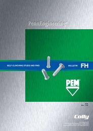
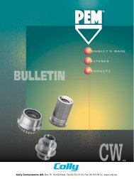
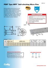
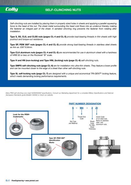
<strong>SELF</strong>-<strong>CLINCHING</strong> <strong>NUTS</strong><strong>SELF</strong>-<strong>CLINCHING</strong> <strong>NUTS</strong>Self-clinching nuts are installed by placing them in properly sized holes in sheets and applying a parallel squeezingforce to the head of the nut. The sheet metal surrounding the head cold flows into an undercut thereby makingthe fastener an integral part of the sheet. A serrated clinching ring prevents the fastener from rotating afterinstallation.Type S, SS, CLS, and CLSS nuts (pages CL-4 and CL-5) provide load-bearing threads in thin sheets with highpushout and torque-out resistance.Type SP, PEM 300 ® nuts (pages CL-4 and CL-5) provide strong load-bearing threads in stainless steel sheetsas thin as .030”/0.8mm.Type CLA aluminum nuts (pages CL-4 and CL-5) are recommended for use in aluminum sheet with a hardnessof HRB 50 or less on the Rockwell “B” scale.Type H and HN (non-locking) and Type HNL (locking) nuts (page CL-6) self-clinching nuts.Type SMPS self-clinching nuts (page CL-6) are for installation into ultra-thin sheets. They feature a lower profileand can be mounted closer to the edge of a sheet than other self-clinching nuts.Type SL self-locking nuts (page CL-7) are designed with a unique and economical TRI-DENT ® locking feature,which meets demanding locking performance requirements.PEM ® <strong>SELF</strong>-<strong>CLINCHING</strong> NUT SELECTOR GUIDEPEMNutTypePageNo.Sheet thickness Reduced Max.as thin as centerline-to- corrosion.025” / 0.64mm Self-locking edge distance resistanceRecommended ApplicationS/SS 4, 5 •CLS/CLSS 4, 5 • •CLA 4, 5 • •Recommended for use Recommended for use Recommended for usein steel or aluminum in aluminum panels in stainless steel panelspanels within specified within specified within specifiedhardness limits hardness limits hardness limitsSP 4, 5 • •H 6 •HN 6 •HNL 6 • •SMPS 6 • • • •SL 7 • •<strong>SELF</strong>-<strong>CLINCHING</strong> FASTENER INSTALLATION DO’S AND DON’TSMany PEM self-clinching nuts meet NASM45938/1specifications. Consult our Marketing department for a complete Military Specifications and NationalAerospace Standards guide (Bulletin NASM) or check our website.Look for the PEM®trademarksType SP, PEM 300 ®IdentificationMarksPART NUMBER DESIGNATIONS – M4 – 2 ZINut Typeand MaterialThread SizeCodeFinish Code:ZI on steel nuts.ShankNone on stainlessCodesteel andFor Min.aluminum nuts.SheetThickness“DO’s”DO select the proper fastener material to meet corrosion requirements.DO make certain that panel material is in the annealed condition. (1)DO make certain that hole punch is kept sharp to minimize work hardening around hole.DO maintain the punch diameter to no greater than +.025mm over the minimum recommended mounting hole for type SP nutsinto stainless steel sheets.DO provide mounting hole of specified size for each fastener.DO install fastener into punch side of sheet.DO make certain that shank (or pilot) is within hole before applying installation force.DO make certain that fastener is not installed adjacent to bends or other highly cold-worked areas.DO apply squeezing force between parallel surfaces.DO utilize recommended installation tooling when installing fasteners.DO apply sufficient force to totally embed clinching ring around entire circumference and to bring shoulder squarely in contactwith sheet. For some fasteners, installation will be complete when the head is flush with the panel surface.“DON’TS”DON’T attempt to install any self-clinching nut other than a type SP fastener into a stainless steel sheet.DON’T install steel or stainless steel fasteners in aluminum panels before anodizing or finishing.DON’T deburr mounting holes on either side of sheet before installing fasteners – deburring will remove metal required forclinching fastener into sheet.DON’T install fastener closer to edge of sheet than minimum edge distance indicated by manufacturer – unless a special fixtureis used to restrict bulging of sheet edge.DON’T over-squeeze. It will crush the head, distort threads, and buckle the sheet. Approximate installation forces are listed inperformance data tables. Use this info as a guide. Be certain to determine optimum installation force by test prior toproduction runs.DON’T attempt to insert fastener with a hammer blow – under any circumstances. A hammer blow won’t permit the sheet metalto flow and develop an interlock with the fastener’s contour.DON’T install screw in the head side of fastener. Install from opposite side so that the fastener load is toward sheet. Theclinching force is designed only to hold the fastener during handling and to resist torque during assembly.DON’T install fastener on pre-painted side of panel.CL-2 PennEngineering • www.pemnet.com PennEngineering • www.pemnet.com CL-3