Thread technology for high-strength fastenings Simple â fast â long ...
Thread technology for high-strength fastenings Simple â fast â long ...
Thread technology for high-strength fastenings Simple â fast â long ...

You also want an ePaper? Increase the reach of your titles
YUMPU automatically turns print PDFs into web optimized ePapers that Google loves.
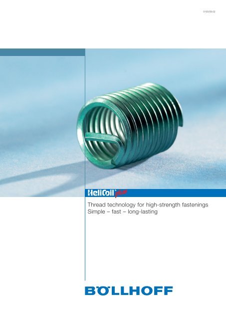
<strong>Thread</strong> <strong>technology</strong> <strong>for</strong> <strong>high</strong>-<strong>strength</strong> <strong><strong>fast</strong>enings</strong><strong>Simple</strong> – <strong>fast</strong> – <strong>long</strong>-lasting0100/09.02
ContentsHELICOIL ® plus thread <strong>technology</strong>SeiteThe system 3The <strong>technology</strong> 3The versions 4The applications 5The advantages 5 – 7Examples of application 8 / 9Materials / thread types 10Design guidelines 11Technical data of the thread inserts 11a – 17STRIPFEED ® magazined thread inserts”pick-and-place“ equipment 18Installation 19System components <strong>for</strong>HELICOIL ® plus installationSeiteApplication engineering 20Standard range of HELICOIL ® plus manual and machine taps 21HELICOIL ® plus machine taps <strong>for</strong> special requirements 22<strong>Thread</strong> tolerances of holding threads 23Manual taps 24 – 27Combined drilling and tapping tools 26 / 27Machine taps and <strong>for</strong>ming taps 28 – 31Gauges <strong>for</strong> HELICOIL ® plus holding threads 32Installation mandrels, electrical and battery taps and installation accessories 33 – 36Mechanical installation tools 37 – 39Parallel arm stand type S and automatic STRIPFEED ® unit 40Parallel arm stand type PR-E 41Manual installation tools 42Mechanical and pneumatic tang break-off tools as well as manualextracting tools 43Mechanical extracting tools and examples of equipment andspecial machines <strong>for</strong> the semi-automatic installation of HELICOIL ® plus 44HELICOIL ® plus repair kits, repair range kits and HELICOIL ® locknuts 45 – 46HELICOIL ® plus production 472
HELICOIL ® plus thread <strong>technology</strong>The system<strong>Thread</strong> inserts create<strong>high</strong>-<strong>strength</strong> <strong><strong>fast</strong>enings</strong>in metal low-<strong>strength</strong>materials and have beenwell established on themarket <strong>for</strong> about 50years. These stainlesssteel thread inserts are<strong>for</strong>med into elastic spiralsin proven quality fromwire with rhombic profile.After installation, the tangcan be broken off at thenotch (predeterminedbreaking point) if throughholethreads shall be theresult.The newest generation of this <strong>technology</strong> iscalled "HELICOIL ® plus".Due to the optimised shape, HELICOIL ® plus is nowmuch easier to install. This is ensured by the entrywhich allows to position and screw in HELICOIL ® pluslike a screw. The tool sleeve with leader cartridgerequired in the past is no <strong>long</strong>er necessary.An installation mandrel with similar dimensions as a tapis all that is required <strong>for</strong> screwing in the thread insert.However, <strong>for</strong>mer tools of the established shape can stillbe used <strong>for</strong> installation.R m = tensile <strong>strength</strong> 1,400 N/mm 2 min.HV = vickers hardness 425 HV 0.2 min.R Z = roughness depth approx. 2.5 μmμ G = reduced thread friction, results in increased preload-<strong>for</strong>ce F Vτ t = reduction in torsion stress in the screw shankThe <strong>technology</strong>HELICOIL ® plus thread inserts feature <strong>high</strong> wear resistance, low thread friction within small tolerances,<strong>high</strong> surface quality as well as corrosion and heat resistance.Per<strong>for</strong>mance limits defined by nut thread and material <strong>strength</strong> are enhanced by the globally establishedHELICOIL ® plus thread <strong>technology</strong>.3
HELICOIL ® plus thread <strong>technology</strong>The versionsHELICOIL ® plus thread inserts are available in two versions: HELICOIL ® plus free running and HELICOIL ® plusscrewlock. Both versions have an optimal design. Like a screw, the thread insert is simply screwed in with aninstallation mandrel. Compared to <strong>for</strong>mer methods of installation, thanks to the there<strong>for</strong>e considerably enhancedprogram of tools that can be used <strong>for</strong> installation, installation times are reduced by up to 20 %. HELICOIL ® plus free runningEvery thread of the thread insert with precision<strong>for</strong>med,rhombic profile is free running. The result isan internal thread true to gauge that can be used onboth sides.The dimensional stability of the ISO thread complieswith DIN 13 6H and <strong>for</strong> special requirements with 4H.The green colour allows easier distinction when theHELICOIL ® plus free running is installed. The colour isgrip-resistant and does not affect the dimension. Ourseal of quality, a rhombic imprint at the end of thelast thread, unmistakably identifies each BöllhoffHELICOIL ® plus free running thread insert as anoriginal. HELICOIL ® plus screwlockThe HELICOIL, ® plus screwlock bears the samebenefits regarding threads as the HELICOIL ® plusfree running. Additionally an integrated screwclamping area serves as a screw-lock. Locking ofthe screw is achieved by one or several polygonalshapedthreads that clamp the flanks of thescrewed-in screw.The result is an elastically resilient frictional locking.The achieved clamping torques can be compared tothe indication in DIN 267 Part 15, ISO 2320 or canalso be adapted to your individual application.Guide values <strong>for</strong> clamping torques are provided inthe table on page 7.Red HELICOIL ® plus screwlock thread inserts, whichalso bear the rhombic imprint, shall only be usedwith screws of a <strong>high</strong>er property class (from 8.8).Common lubricants according to the manufacturers’recommendations shall be used <strong>for</strong> <strong>high</strong>ly alloyedscrews.The same tightening procedures and torques as <strong>for</strong>HELICOIL ® plus free running apply.4
HELICOIL ® plus thread <strong>technology</strong>The applicationsHELICOIL ® plus ensures <strong>high</strong>-<strong>strength</strong> threads transferring <strong>for</strong>cesfrom flank to flank into the holding thread. This is a system of <strong>high</strong>reliability <strong>for</strong> which German and international industrial propertyrights have been filed and which is available worldwide.HELICOIL ® plus provides thread inserts produced according toconsistent material and quality specifications. This <strong>technology</strong> isthe basis of national standardisation, aeronautical standards andDamaged threadRepaired threadmilitary standards. Apart from that, leading large-scale users base their manufacturing standards on this system. Structural componentWherever low-<strong>strength</strong> materials (e.g. aluminium, aluminiummagnesium alloys and fibre-rein<strong>for</strong>cedplastics) are used, HELICOIL ® plus is indispensable <strong>for</strong> thread rein<strong>for</strong>cement. This applies particularly tomechanical and plant engineering, the automotive industry, electrical and medical engineering as well as to theaerospace industry. <strong>Thread</strong> rein<strong>for</strong>cement excludes wear of the nut thread – even <strong>for</strong> frequent use.HELICOIL ® plus allows miniaturisation and lightweight construction upon the development of serial parts.The required <strong>strength</strong> is ensured by thread rein<strong>for</strong>cement with HELICOIL ® plus. Rejects recovery and thread repairHELICOIL ® plus thread inserts are internationally released <strong>for</strong> economical and permanent repair of damagedand worn out threads.Apart from repair of valuable individual components, the possibility to return large-scale components which havebeen rejected due to faults upon thread production to the production process is of major importance.The advantages Wear resistanceHELICOIL ® plus threadinserts are made ofaustenitic chromenickelsteel (minimumtensile <strong>strength</strong> of1,400 N/mm²).The rolled nut threadhas a <strong>high</strong> surfacequality. This ensures a<strong>high</strong>-<strong>strength</strong>, wearresistantthread with anextremely small andconstant thread frictiontorque. In case ofrepeated screwingsand if an even tighteningtorque is applied,a <strong>high</strong>er and even preload-<strong>for</strong>ce is there<strong>for</strong>e achieved. This also leads to an improved utilisation of the yieldpoint of <strong>high</strong>-<strong>strength</strong> screws. Torsion stress is considerably reduced: Compared to tapped threads, surfaceroughness of HELICOIL ® plus is up to 90 percent smaller.5
HELICOIL ® plus thread <strong>technology</strong>The advantages StrengthThe flexible characteristics of the HELICOIL ® plusthread insert ensure even load and stress distributionand there<strong>for</strong>e optimum flank contact. Deficientpitches and angles are compensated over the entirelength of the thread insert. With this, an optimum<strong>for</strong>ce transmission from bolt to nut thread isachieved. The quality of screwed connections isconsiderably inscreased — <strong>for</strong> static as well as<strong>for</strong> dynamic operating loads.The improved distribution of preload-<strong>for</strong>ce increasesthe fatigue <strong>strength</strong> of dynamically loaded screws.This is why HELICOIL ® are also suitable <strong>for</strong> <strong>high</strong><strong>strength</strong>holding thread materials, e.g. steel or castiron alloys. Resistance to corrosion and thermal effectsThe basic material of HELICOIL ® plus ensures thatscrews do not seize under normal environmentalinfluences. For thermally <strong>high</strong>ly stressed screwedconnections, HELICOIL ® plus thread inserts of nickelbasis materials with and without coating are available.Elasticity and spring <strong>for</strong>ce are constant evenunder <strong>high</strong> temperatures.If materials which are susceptible to corrosion, suchas magnesium, are used, HELICOIL ® plus is employedas a special hard-coated version of <strong>high</strong><strong>strength</strong>aluminium. Contact corrosion can there<strong>for</strong>e be ruledout.6
HELICOIL ® plus thread <strong>technology</strong>The advantages Freedom of designHELICOIL ® plus thread inserts leave the engineer arelatively free choice of materials and materialthicknesses. With a maximum <strong>strength</strong> thanks tothread rein<strong>for</strong>cement, HELICOIL ® plus meets thecurrent trend towards lightweight construction (e.g.of magnesium) requiring only minimum space. Dueto a reduced number of joints, reduced screwdimensions, less material, reduced installation spaceand weight, HELICOIL ® plus considerably contributesto a cost reduction <strong>for</strong> equal or <strong>high</strong>er requirements.– shorter lengths of thread engagement– small screw, <strong>high</strong>er property classwithoutHELICOIL ® pluswithHELICOIL ® plus Tight fitThe outside diameter of the HELICOIL ® plus thread insert in not installed state is by a defined measure largerthan the holding thread. Combined with the <strong>high</strong> spring <strong>for</strong>ce of the material, this difference in dimension resultsin radial expansion and there<strong>for</strong>e in the tight and clearance-free fit in the nut thread.Additional locking elements or adhesive – as common <strong>for</strong> fixed bushings – are not required anymore. If you usean impact wrench, please contact our technical consultant.Screw locking with HELICOIL ® plus screwlock<strong>Thread</strong> <strong>technology</strong> and the polygonal-shaped thread of HELICOIL ® plus screwlockensure a <strong>high</strong> degree of frictional locking and thus locking of the screw againstself-unscrewing. Additional locking of the joint with split pins, wires or washers is notnecessary. This reduces costs and allows easier installation.Guide values <strong>for</strong> clamping torques according to DIN 267 Part 15 or ISO 2320valid <strong>for</strong> coarse threads and fine threadsvalues in Nm <strong>for</strong> property classes 8<strong>Thread</strong>s M 3 M 4 M 5 M 6 M 8 M 10 M 12 M 14 M 16 M 18 M 201st screwing-on, max. 0.43 0.90 1.60 3.00 6.00 10.5 15.5 24.0 32.0 42.0 54.01st screwing-off, min. 0.12 0.18 0.29 0.45 0.85 1.5 2.3 3.3 4.5 6.0 7.55th screwing-off, min. 0.08 0.12 0.20 0.30 0.60 1.0 1.6 2.3 3.0 4.2 5.3Clamping torques <strong>for</strong> other metric threads on request.7
Examples of application <strong>for</strong> HELICOIL ® plus thread insertsAutomotive, aerospace industry Gear box housing of magnesium alloys <strong>Thread</strong> rein<strong>for</strong>cement <strong>for</strong> oil drain plugs Exhaust systems Satellite <strong>technology</strong> Aeroplane enginesSteering gear casingsof aluminiumHELICOIL ® plusM 14 x 1.5 x 14free running Repeated screwings Maintenance and repairElectronics, sheet metal, plastic Lamps Electrical appliances Drill hammerMounting plate <strong>for</strong> electricalcomponents of die-castaluminiumMachines and plants Printing presses High-temperature areas Translation threads (adjusting screws) Repeated screwings Maintenance and repairMechanical engineeringconsoleMaterial: G-AlSi9 MgHELICOIL ® plusM 8 x 12 free runningFurther examples of applicationOil drain hole of a car oil sumpof aluminium.<strong>Thread</strong> rein<strong>for</strong>cement withHELICOIL ® plusM 14 x 1.5 x 14 free running8
Further examples of application <strong>for</strong> HELICOIL ® plus thread insertsCover of a car gear box of castaluminium HELICOIL ® plusM 6 x 6 free runningFitting of car roof railsCast aluminium withHELICOIL ® plusM 6 x 6 screwlockHousing of aluminium castingalloy.Flange with HELICOIL ® plusM 5 x 10 screwlockGear box housing of an anglegrinder of aluminiumHELICOIL ® plusM 10 x 15 screwlockHELICOIL ® plusM 6 x 12 free runningEngine support <strong>for</strong> gardenchipper of aluminium.Screw locking device withHELICOIL ® plus screwlockM 8 x 12Housing <strong>for</strong> electricalcomponents of aluminiumHELICOIL ® plus screwlockCrossing protection of flushmountedlamp.Material: cast aluminiumHELICOIL ® plus M 8 x 12free runningNuts in <strong>high</strong>-temperatureapplications with HELICOIL ®insert of INCONEL –silvered and nuts withHELICOIL ® screwlock as thelocking device9
HELICOIL ® plus thread <strong>technology</strong>Materials<strong>Thread</strong> insert Minimum tensile AvailableTemperature <strong>strength</strong> at room surface Examples of useMaterials ➀ resistance temperature treatment ➀Stainless steel A 2 low temp. -196°C 1400 N/mm 2 – without Standard applications general lightweightX5 CrNi 18 10 short-term 425°C – waxed <strong>for</strong> all property e.g. of aluminiumMaterial No 1.4301 <strong>long</strong>-term 315°C – dry lubri- classes and or magnesiumcating film materials ➂ alloys ➁– cadmium-Stainless steel A 4 low temp. -196°C 1400 N/mm 2 plated – increased corrosion general lightweightX6 CrNiMoTi 17 12 2 ➃ short-term 425°C– silveredprotectionconstructionMaterial No 1.4571 <strong>long</strong>-term 315°C– <strong>high</strong>ly alloyed CrNi sea water /steel screws ➂ chlorine-containing– low thread waterfrictionBronze short-term 300°C 900 N/mm 2 – without – Cu workpiecesCuSN 6 <strong>long</strong>-term 250°C – cadmium- – translation threadsMaterial No 2.1020.34 plated – CrNi screwsInconel X 750 short-term 750°C 1150 N/mm 2 – without – thermal load in – aerospaceNiCr 15 Fe 7 TiAl <strong>long</strong>-term 550°C – silvered combination with <strong>technology</strong>Material No 2.4669 corrosion protection – aeroplane enginesNimonic 90 short-term 900°C – turbochargerNiCr 20 Co 18 Ti <strong>long</strong>-term 600°CMaterial No 2.4632Aluminium short-term 170°C 500 N/mm 2 – hard-coated – magnesium – vehicle technolo.AlZnMgCu 1,5 <strong>long</strong>-term 150°C – dry lubricating workpieces – lightweightMaterial No 3.4365 film construction Other materials and surfaces on request If magnesium alloys are used outdoors, special measures are recommended <strong>for</strong> corrosion protection If CrNi screws are used, a suitable coating or common lubricant is recommended Delivery on requestNotes: Data only apply to uncoloured HELICOIL ® plus.Up to M 5, the applied colour is temperature-resistant from -18 °C to 200 °C.From M 6, the applied colour is temperature-resistant from -5°C to -120 °C (+150 °C short-term).<strong>Thread</strong> typesMetric ISO threadCoarse threadHELICOIL ® plus free runningHELICOIL ® plus screwlock<strong>Thread</strong>s Nominal Nominal Nominal Nominal Pagediameter length diameter lengthM 2 to M 68 0.5 d to 3 d M 2 to M 39 0.75 d to 3 d ➄Metric ISO threadM 8 x 1 toM 8 x 1 to0.5 d to 3 dFine thread M 160 x 6 M 64 x 40.75 d to 3 dPipe thread ISO 228/1British Standard Pipe <strong>Thread</strong>G 1/8" to G 1 1/2" 1 d to 2,5 d – –= BSPUNIFIED or American NationalCoarse <strong>Thread</strong> Series = UNC/NC2-56 to 1 1/2"-6 1 d to 2.5 d 2-56 to 3/4"-16 1 d to 2.5 dUNIFIED or American NationalFine <strong>Thread</strong> Series = UNF/NF3-56 to 1 1/2"-12 1 d to 2.5 d 3-56 to 3/4"-16 1 d to 2.5 dBritish Standard WhitworthCoarse <strong>Thread</strong> Series = BSW1/8" to 1 1/2" 1 d to 2.5 d 5/16" to 3/4" 1 d to 3 dBritish Standard Fine <strong>Thread</strong>Series = BSF3/16" to 1 1/2" 1 d to 2.5 d 3/16" to 3/4" 1 d to 2.5 dBritish Association Standard<strong>Thread</strong> = BA0BA to 6BA 1 d to 2.5 d 0BA 2BA 4BA 6BA 1 d to 2.5 d12-17seecat.0101 Not possible <strong>for</strong> M 2 and M 2.5.HELICOIL ® plus thread inserts comply with many requirements and standards of industry and aerospace industry.Among these are: DIN 8140, DIN 65536, LN 9039, LN 9499.Further standards (e.g. MS or EN standards) on request.10
HELICOIL ® plus thread <strong>technology</strong> design guidelinesDetermination of nominal lengthHELICOIL ® plus thread insertsTechnical dataGuide values to determine minimum length of the HELICOIL ® plus thread insert depending on mounting materialand screw property class, valid <strong>for</strong> temperature of 20 °CStrength ofmounting materialTensile <strong>strength</strong> 3.6 4.8 5.8 6.8R m (N/mm 2 ) 4.6 5.6 6.6 6.9Screw property class8.8 9.8 10.9 12.9 14.9up to 100 1.5 d 1.5 d 2 d 2.5 d 3 d 3 d – – –> 100 – 150 1.5 d 1.5 d 2 d 2 d 2.5 d 2.5 d 2.5 d 2.5 d 3 d> 150 – 200 1 d 1.5 d 1.5 d 1.5 d 2 d 2 d 2 d 2.5 d 2.5 d> 200 – 250 1 d 1 d 1.5 d 1.5 d 1.5 d 1.5 d 2 d 2.5 d 2.5 d> 250 – 300 1 d 1 d 1 d 1 d 1.5 d 1.5 d 1.5 d 2 d 2 d> 300 – 350 1 d 1 d 1 d 1 d 1 d 1.5 d 1.5 d 1.5 d 2 d> 350 – 400 1 d 1 d 1 d 1 d 1 d 1 d 1.5 d 1.5 d 1.5 d> 400 – 000 1 d 1 d 1 d 1 d 1 d 1 d 1.5 d 1.5 d 1.5 dshear stressThe table of values to determine the minimum lengths applies to aluminium as well as to materials with a ratio of = 0.6 to 0.7shear stresstensile stressSome iron casting alloys have a ratio of = 0.8 to 1.4 (Source VDI 2230)tensile stressFor these guide values, the screw is the weaker joint member.Lengths can be shorter than the recommended nominal lengths if tests confirm this.Intermediate lengths are also available.Temperature limits <strong>for</strong> validity: aluminium alloys T max = 300°C, magnesium alloys T max = 100°C.For the design of screwed connections under thermal stress, the changes of temperature-dependent materialparameters must be taken into account.Minimum wall thicknessThe minimum wall thickness mainly depends on individualoperating data. These define material <strong>strength</strong> andlength of thread engagement. The indicated guide value<strong>for</strong>mulas apply to aluminium, cast and wroughtalloys and a length of thread engagement of theHELICOIL ® plus of 1.5 d.d = nominal diameterD HC = outside diameter of the holding threada = residual wall thicknessDiagrammatic representation with the example of M 10 x 15:HELICOIL ® plus thread insert installedM 10 M 10 M 10HELICOIL ® plusHELICOIL ® plusHELICOIL ® plus4130 0100 0154130 0100 0154130 0100 01514.214.2max. 14.2HELICOIL ® plus thread insert installed,with screwTang removedTang not removedTo read the table,please open this page.1111 a
HELICOIL ® plus thread insertsHELICOIL ® plus thread insertsfree runningWnotchscrewlockWnotcht 2 min.* d 1 D 1HC D HCmin. min. free running screwlockd P 00x d mm W max. max. B t 3 max. min. Order No ➀ Order No ➀d 1d 1tangThe control values of not installed thread inserts free runningand screwlock are W and d 1.This length can only be measured <strong>for</strong> installed thread inserts.Holding threadAssemblytang1.0 d 2.0 2.9 1.8 4130 002 00021.5 d 3.0 4.92.8 4130 002 00032.6 2.09M 2 0.40 2.0 d 4.0 6.92.1 3.8 2.52 4130 002 0004 on request2.8 2.182.5 d 5.0 8.9 4.8 4130 002 00053.0 d 6.0 10.9 5.8 4130 002 00061.0 d 2.5 3.5 2.3 4130 025 0025 4132 025 00251.5 d 3.75 5.93.5 4130 025 0375 4132 025 03753.3 2.60M 2.5 0.45 2.0 d 5.0 8.12.6 4.8 3.08 4130 025 0005 4132 025 00053.5 2.702.5 d 6.25 10.5 6.0 4130 025 0625 4132 025 06253.0 d 7.5 12.9 7.3 4130 025 0075 4132 025 00751.0 d 3.0 3.9 2.7 4130 003 0003 4132 003 00031.5 d 4.5 6.34.2 4130 003 0045 4132 003 00453.8 3.11M 3 0.5 2.0 d 6.0 8.73.2 5.7 3.65 4130 003 0006 4132 003 00064.0 3.222.5 d 7.5 11.1 7.2 4130 003 0075 4132 003 00753.0 d 9.0 13.5 8.7 4130 003 0009 4132 003 0009d = nominal thread diameterP = thread pitchd 1 = outside diameter of thread insert prior to installationW = number of threads prior to installationD HC = outside diameter of holding threadD 1HC = crest diameterB = Suitable twist drill diameter. Please note: D 1HC isdecisive <strong>for</strong> selecting the correct twist drill diameter.t 1 = minimum depth of tap hole according to DIN 76 –Part 1 (guide value)t 2 = The nominal length of the thread insert correspondsto the minimum length of the full holding thread <strong>for</strong>blind holes or to the minimum plate thickness <strong>for</strong> athrough hole.t 3 = maximum screw-in depth <strong>for</strong> not broken off tangt 5 = distance of the thread insert to the joint face = 0.25to 0.5 P, if t 2 corresponds to the above-mentionedminimum value Prior to tapping, counter-bore 90° and deburr.Outside diameter of upset part = D HC + 0.1 mm. When HELICOIL ® plus thread inserts are used in seriesproduction, we recommend to add at least 1 x P to values t 1and t 2. Materials or surfaces are to be indicated with the 5th digit ofthe Order no:Beispiel:0 = stainless steel A2, X 5 CrNi 18 10 4130 002 00051 = bronze, CuSn 62 = Nimonic 90, NiCr 20 Co 18 Ti, silvered*3 = stainless steel A4, X 6 CrNiMoTi 17 12 24 = Inconel X 750, NiCr 15 Fe 7 TiAl, silvered*5 = Inconel X 750, NiCr 15 Fe 7 TiAl, bright6 = stainless steel A2, X 5 CrNi 18 10, cadmium-plated7 = stainless steel A2, X 5 CrNi 18 10, magazined**8 = bronze, CuSn 6, magazined**Other materials on request.** Use special tools.** See page 18.All measures in mm. Technical modifications reserved.1.0 d 3.5 3.7 3.2 4130 035 0035 4132 035 00351.5 d 5.25 6.35.0 4130 035 0053 4132 035 00534.42 3.63M 3.5 0.6 2.0 d 7.0 8.73.7 6.7 4.28 4130 035 0007 4132 035 00074.60 3.762.5 d 8.75 11.2 8.5 4130 035 0875 4132 035 08753.0 d 10.5 13.3 10.2 4130 035 0105 4132 035 01051.0 d 4.0 3.7 3.6 4130 004 0004 4132 004 00041.5 d 6.0 6.15.6 4130 004 0006 4132 004 00065.05 4.15M 4 0.7 2.0 d 8.0 8.44.2 7.6 4.91 4130 004 0008 4132 004 00085.25 4.292.5 d 10.0 10.9 9.6 4130 004 0010 4132 004 00103.0 d 12.0 13.2 11.6 4130 004 0012 4132 004 00121.0 d 5.0 4.3 4.6 4130 005 0005 4132 005 00051.5 d 7.5 6.97.1 4130 005 0075 4132 005 00756.35 5.17M 5 0.8 2.0 d 10.0 9.75.2 9.6 6.04 4130 005 0010 4132 005 00106.6 5.332.5 d 12.5 12.3 12.1 4130 005 0125 4132 005 01253.0 d 15.0 14.8 14.6 4130 005 0015 4132 005 00151.0 d 6.0 4.2 5.5 4130 006 0006 4132 006 00061.5 d 9.0 6.98.5 4130 006 0009 4132 006 00097.6 6.22M 6 1.0 2.0 d 12.0 9.66.3 11.5 7.30 4130 006 0012 4132 006 00127.85 6.412.5 d 15.0 12.3 14.5 4130 006 0015 4132 006 00153.0 d 18.0 14.6 17.5 4130 006 0018 4132 006 00181.0 d 7.0 5.3 6.5 4130 007 0007 4132 007 00071.5 d 10.5 8.210.0 4130 007 0105 4132 007 01058.65 7.22M 7 1.0 2.0 d 14.0 11.17.3 13.5 8.30 4130 007 0014 4132 007 00148.9 7.412.5 d 17.5 14.3 17.0 4130 007 0175 4132 007 01753.0 d 21.0 17.4 20.5 4130 007 0021 4132 007 00211.0 d 8.0 4.7 7.4 4130 008 0008 4132 008 00081.5 d 12.0 7.411.4 4130 008 0012 4132 008 00129.85 8.27M 8 1.25 2.0 d 16.0 10.68.4 15.4 9.62 4130 008 0016 4132 008 001610.1 8.482.5 d 20.0 13.5 19.4 4130 008 0020 4132 008 00203.0 d 24.0 16.4 23.4 4130 008 0024 4132 008 00241.0 d 8.0 6.1 7.5 4130 008 3008 4132 008 30081.5 d 12.0 9.511.5 4130 008 3012 4132 008 30129.85 8.22M 8 x 1 1.0 2.0 d 16.0 12.98.3 15.5 9.30 4130 008 3016 4132 008 301610.1 8.412.5 d 20.0 16.5 19.5 4130 008 3020 4132 008 30203.0 d 24.0 19.9 23.5 4130 008 3024 4132 008 3024* Intermediate lengths also available. See flap page 11b.11 b 12
HELICOIL ® plus thread insertst 2 min.* d 1 D 1HC D HCmin. min. free running screwlockd P 00x d mm W max. max. B t 3 max. min. Order No ➀ Order No ➀1.0 d 9.0 5.3 8.4 4130 009 00091.5 d 13.5 8.612.9 4130 009 013510.85 9.27M 9 1.25 2.0 d 18.0 11.99.4 17.4 10.62 4130 009 0018 on request11.1 9.482.5 d 22.5 15.3 21.9 4130 009 02253.0 d 27.0 18.1 26.4 4130 009 00271.0 d 10.0 5.0 9.2 4130 010 0010 4132 010 00101.5 d 15.0 8.114.2 4130 010 0015 4132 010 001512.1 10.32M 10 1.5 2.0 d 20.0 11.210.50 19.2 11.95 4130 010 0020 4132 010 002012.5 10.562.5 d 25.0 14.2 24.2 4130 010 0025 4132 010 00253.0 d 30.0 17.2 29.2 4130 010 0030 4132 010 00301.0 d 10.0 7.6 9.5 4130 010 3010 4132 010 30101.5 d 15.0 12.114.5 4130 010 3015 4132 010 301512.1 10.22M 10 x 1 1.0 2.0 d 20.0 16.310.25 19.5 11.30 4130 010 3020 4132 010 302012.5 10.412.5 d 25.0 20.7 24.5 4130 010 3025 4132 010 30253.0 d 30.0 25.0 29.5 4130 010 3030 4132 010 30301.0 d 10.0 6.0 9.4 4130 010 9010 4132 010 90101.5 d 15.0 9.714.4 4130 010 9015 4132 010 901512.1 10.27M 10 x 1.25 1.25 2.0 d 20.0 13.110.40 19.4 11.62 4130 010 9020 4132 010 902012.5 10.482.5 d 25.0 16.9 24.4 4130 010 9025 4132 010 90253.0 d 30.0 20.1 29.4 4130 010 9030 4132 010 90301.0 d 11.0 5.6 10.2 4130 011 00111.5 d 16.5 9.015.7 4130 011 016513.1 11.33M 11 1.5 2.0 d 22.0 12.311.50 21.2 12.95 4130 011 0022 on request13.5 11.562.5 d 27.5 15.7 26.7 4130 011 02753.0 d 33.0 19.1 32.2 4130 011 00331.0 d 12.0 5.2 11.1 4130 012 0012 4132 012 00121.5 d 18.0 8.417.1 4130 012 0018 4132 012 001814.4 12.38M 12 1.75 2.0 d 24.0 11.712.50 23.1 14.27 4130 012 0024 4132 012 002414.8 12.642.5 d 30.0 14.7 29.1 4130 012 0030 4132 012 00303.0 d 36.0 18.0 35.1 4130 012 0036 4132 012 00361.0 d 12.0 9.3 11.5 4130 012 30121.5 d 18.0 14.517.5 4130 012 301814.4 12.22M 12 x 1 1.0 2.0 d 24.0 19.512.25 23.5 13.30 4130 012 3024 on request14.8 12.412.5 d 30.0 24.8 29.5 4130 012 30303.0 d 36.0 30.0 35.5 4130 012 30361.0 d 12.0 7.4 11.4 4130 012 9012 4132 012 90121.5 d 18.0 11.617.4 4130 012 9018 4132 012 901814.4 12.27M 12 x 1.25 1.25 2.0 d 24.0 15.912.25 23.4 13.62 4130 012 9024 4132 012 902414.8 12.482.5 d 30.0 20.0 29.4 4130 012 9030 4132 012 90303.0 d 36.0 24.3 35.4 4130 012 9036 4132 012 90361.0 d 12.0 6.2 11.2 4130 012 4012 4132 012 40121.5 d 18.0 9.817.2 4130 012 4018 4132 012 401814.4 12.32M 12 x 1.5 1.5 2.0 d 24.0 13.512.50 23.2 13.95 4130 012 4024 4132 012 402414.8 12.562.5 d 30.0 17.1 29.2 4130 012 4030 4132 012 40303.0 d 36.0 20.8 35.2 4130 012 4036 4132 012 4036* Intermediate lengths also available.See flap page 11b.13
HELICOIL ® plus thread insertst 2 min.* d 1 D 1HC D HCmin. min. free running screwlockd P 00x d mm W max. max. B t 3 max. min. Order No ➀ Order No ➀1.0 d 14.0 5.6 13.0 4130 014 0014 4132 014 00141.5 d 21.0 8.820.0 4130 014 0021 4132 014 002116.8 14.43M 14 2.0 2.0 d 28.0 12.014.50 27.0 16.60 4130 014 0028 4132 014 002817.2 14.732.5 d 35.0 15.2 34.0 4130 014 0035 4132 014 00351.0 d 14.0 11.2 13.5 4130 014 30141.5 d 21.0 17.2 16.8 14.22 20.5 4130 014 3021M 14 x 1 1.0 2.0 d 28.0 23.2 17.2 14.41 14.25 27.5 15.30 4130 014 30282.5 d 35.0 29.2 34.5 4130 014 3035on request8.4 4.6 7.8 4130 014 908412.4 7.4 16.8 14.27 11.8 4130 014 9124M 14 x 1.25 1.25 14.4 9.1 17.2 14.48 14.25 13.8 15.62 4130 014 914416.4 10.2 15.8 4130 014 9164spark plugthreadon request1.0 d 14.0 7.4 13.2 4130 014 4014 4132 014 40141.5 d 21.0 11.6 16.8 14.38 20.2 4130 014 4021 4132 014 4021M 14 x 1.5 1.5 2.0 d 28.0 15.7 17.2 14.56 14.50 27.2 15.95 4130 014 4028 4132 014 40282.5 d 35.0 19.9 34.2 4130 014 4035 4132 014 40351.0 d 16.0 6.5 15.0 4130 016 0016 4132 016 00161.5 d 24.0 10.1 19.0 16.43 23.0 4130 016 0024 4132 016 0024M 16 2.0 2.0 d 32.0 13.8 19.4 16.73 16.50 31.0 18.60 4130 016 0032 4132 016 00322.5 d 40.0 17.5 39.0 4130 016 0040 4132 016 00401.0 d 16.0 8.7 15.2 4130 016 4016 4132 016 40161.5 d 24.0 13.4 19.0 16.32 23.2 4130 016 4024 4132 016 4024M 16 x 1.5 1.5 2.0 d 32.0 18.1 19.4 16.56 16.50 31.2 17.95 4130 016 4032 4132 016 40322.5 d 40.0 22.9 39.2 4130 016 4040 4132 016 40400.50 d 9.0 2.3 7.7 4130 018 0009 4132 018 00090.75 d 13.5 3.812.2 4130 018 0135 4132 018 013521.5 18.54M 18 2.5 1.00 d 18.0 5.618.75 16.7 21.25 4130 018 0018 4132 018 001822.0 18.901.50 d 27.0 9.0 25.7 4130 018 0027 4132 018 00272.00 d 36.0 12.3 34.7 4130 018 0036 4132 018 00360.50 d 9.0 4.2 8.2 4130 018 4009 4132 018 40090.75 d 13.5 7.012.7 4130 018 4135 4132 018 413521.5 18.32M 18 x 1.5 1.5 1.00 d 18.0 9.518.50 17.2 19.95 4130 018 4018 4132 018 401822.0 18.561.50 d 27.0 14.9 26.2 4130 018 4027 4132 018 40272.00 d 36.0 20.2 35.2 4130 018 4036 4132 018 40360.50 d 9.0 3.1 8.0 4130 018 5009 4132 018 50090.75 d 13.5 5.112.5 4130 018 5135 4132 018 513521.5 18.43M 18 x 2 2.0 1.00 d 18.0 7.118.50 17.0 20.60 4130 018 5018 4132 018 501822.0 18.721.50 d 27.0 11.2 26.0 4130 018 5027 4132 018 50272.00 d 36.0 15.1 35.0 4130 018 5036 4132 018 5036* Intermediate lengths also available.See flap page 11b.14
HELICOIL ® plus thread insertst 2 min.* d 1 D 1HC D HCmin. min. free running screwlockd P 00x d mm W max. max. B t 3 max. min. Order No ➀ Order No ➀0.50 d 10.0 2.7 8.7 4130 020 0010 4132 020 00100.75 d 15.0 4.513.7 4130 020 0015 4132 020 001523.7 20.54M 20 2.5 1.00 d 20.0 6.320.75 18.7 23.25 4130 020 0020 4132 020 002024.2 20.901.50 d 30.0 10.0 28.7 4130 020 0030 4132 020 00302.00 d 40.0 13.7 38.7 4130 020 0040 4132 020 00400.50 d 10.0 4.9 9.2 4130 020 4010 4132 020 40100.75 d 15.0 7.914.2 4130 020 4015 4132 020 401523.7 20.32M 20 x 1.5 1.5 1.00 d 20.0 10.720.50 19.2 21.95 4130 020 4020 4132 020 402024.2 20.561.50 d 30.0 16.7 29.2 4130 020 4030 4132 020 40302.00 d 40.0 22.4 39.2 4130 020 4040 4132 020 40400.50 d 10.0 3.5 9.0 4130 020 5010 4132 020 50100.75 d 15.0 5.814.0 4130 020 5015 4132 020 501523.7 20.43M 20 x 2 2.0 1.00 d 20.0 8.020.50 19.0 22.60 4130 020 5020 4132 020 502024.2 20.731.50 d 30.0 12.5 29.0 4130 020 5030 4132 020 50302.00 d 40.0 16.8 39.0 4130 020 5040 4132 020 50400.50 d 11.0 3.0 9.7 4130 022 0011 4132 022 00110.75 d 16.5 5.015.2 4130 022 0165 4132 022 016526.3 22.54M 22 2.5 1.00 d 22.0 6.922.75 20.7 25.25 4130 022 0022 4132 022 002226.8 22.901.50 d 33.0 10.9 31.7 4130 022 0033 4132 022 00332.00 d 44.0 15.0 42.7 4130 022 0044 4132 022 00440.50 d 11.0 5.5 10.2 4130 022 40110.75 d 16.5 8.615.7 4130 022 416526.3 22.32M 22 x 1.5 1.5 1.00 d 22.0 11.722.50 21.2 23.95 4130 022 4022 on request26.8 22.561.50 d 33.0 18.1 32.2 4130 022 40332.00 d 44.0 24.5 43.2 4130 022 40440.50 d 11.0 3.9 10.0 4130 022 5011 4132 022 50110.75 d 16.5 6.415.5 4130 022 5165 4132 022 516526.3 22.43M 22 x 2 2.0 1.00 d 22.0 8.722.50 21.0 24.60 4130 022 5022 4132 022 502226.8 22.731.50 d 33.0 13.6 32.0 4130 022 5033 4132 022 50332.00 d 44.0 18.4 43.0 4130 022 5044 4132 022 50440.50 d 12.0 2.6 10.5 4130 024 0012 4132 024 00120.75 d 18.0 4.516.5 4130 024 0018 4132 024 001828.6 24.65M 24 3.0 1.00 d 24.0 6.224.75 22.5 27.90 4130 024 0024 4132 024 002429.1 25.051.50 d 36.0 10.0 34.5 4130 024 0036 4132 024 00362.00 d 48.0 14.0 46.5 4130 024 0048 on request0.50 d 12.0 6.0 11.2 4130 024 40120.75 d 18.0 9.517.2 4130 024 401828.6 24.33M 24 x 1.5 1.5 1.00 d 24.0 12.924.50 23.2 25.95 4130 024 4024 on request29.1 24.561.50 d 36.0 19.8 35.2 4130 024 40362.00 d 48.0 26.7 47.2 4130 024 40480.50 d 12.0 4.3 11.0 4130 024 5012 4132 024 50120.75 d 18.0 7.017.0 4130 024 5018 4132 024 501828.6 24.43M 24 x 2 2.0 1.00 d 24.0 9.624.50 23.0 26.60 4130 024 5024 4132 024 502429.1 24.731.50 d 36.0 15.0 35.0 4130 024 5036 4132 024 50362.00 d 48.0 20.2 47.0 4130 024 5048 4132 024 5048* Intermediate lengths also available.See flap page 11b.15
HELICOIL ® plus thread insertst 2 min.* d 1 D 1HC D HCmin. min. free running screwlockd P 00x d mm W max. max. B t 3 max. min. Order No ➀ Order No ➀0.50 d 13.0 6.5 12.2 4130 026 40130.75 d 19.5 10.318.7 4130 026 419531.0 26.33M 26 x 1.5 1.5 1.00 d 26.0 14.026.50 25.2 27.95 4130 026 4026 on request31.5 26.561.50 d 39.0 21.6 38.2 4130 026 40392.00 d 52.0 29.1 51.2 4130 026 40520.50 d 13.5 3.2 12.0 4130 027 0135 4132 027 01350.75 d 20.3 5.018.8 4130 027 0203 4132 027 020332.2 27.65M 27 3.0 1.00 d 27.0 7.127.75 25.5 30.90 4130 027 0027 4132 027 002732.7 28.051.50 d 40.5 11.4 39.0 4130 027 0405 4132 027 04052.00 d 54.0 15.4 52.5 4130 027 0054 4132 027 00540.50 d 13.5 6.7 12.7 4130 027 41350.75 d 20.3 10.719.5 4130 027 420332.2 27.33M 27 x 1.5 1.5 1.00 d 27.0 14.627.50 26.2 28.95 4130 027 4027 on request32.7 27.561.50 d 40.5 22.6 39.7 4130 027 44052.00 d 54.0 30.0 53.2 4130 027 40540.50 d 13.5 5.1 12.5 4130 027 51350.75 d 20.3 7.919.3 4130 027 520332.2 27.43M 27 x 2 2.0 1.00 d 27.0 10.827.50 26.0 29.60 4130 027 5027 on request32.7 27.731.50 d 40.5 16.8 39.5 4130 027 54052.00 d 54.0 22.6 53.0 4130 027 50540.50 d 14.0 7.1 13.2 4130 028 40140.75 d 21.0 11.120.2 4130 028 402133.1 28.33M 28 x 1.5 1.5 1.00 d 28.0 15.228.50 27.2 29.95 4130 028 4028 on request33.6 28.561.50 d 42.0 23.3 41.2 4130 028 40422.00 d 56.0 31.4 55.2 4130 028 40560.50 d 15.0 3.0 13.2 4130 030 0015 4132 030 00150.75 d 22.5 4.920.7 4130 030 0225 4132 030 022535.2 30.76M 30 3.5 1.00 d 30.0 7.031.00 28.2 34.55 4130 030 0030 4132 030 003035.7 31.211.50 d 45.0 11.0 43.2 4130 030 0045 4132 030 00452.00 d 60.0 14.9 58.2 4130 030 0060 4132 030 00600.50 d 15.0 7.8 14.2 4130 030 40150.75 d 22.5 12.221.7 4130 030 422535.2 30.33M 30 x 1.5 1.5 1.00 d 30.0 16.530.50 29.2 31.95 4130 030 4030 on request35.7 30.561.50 d 45.0 25.3 44.2 4130 030 40452.00 d 60.0 34.0 59.2 4130 030 40600.50 d 15.0 5.7 14.0 4130 030 50150.75 d 22.5 9.021.5 4130 030 522535.2 30.43M 30 x 2 2.0 1.00 d 30.0 12.330.50 29.0 32.60 4130 030 5030 on request35.7 30.731.50 d 45.0 19.0 44.0 4130 030 50452.00 d 60.0 25.5 59.0 4130 030 50600.50 d 16.5 3.4 14.7 4130 033 0165 on request0.75 d 24.8 5.623.0 4130 033 0248 on request38.3 33.76M 33 3.5 1.00 d 33.0 7.834.00 31.2 37.55 4130 033 0033 4132 033 003338.8 34.211.50 d 49.5 12.2 47.7 4130 033 0495 4132 033 04952.00 d 66.0 16.5 64.2 4130 033 0066 4132 033 0066* Intermediate lengths also available.See flap page 11b.16
HELICOIL ® plus thread insertst 2 min.* d 1 D 1HC D HCmin. min. free running screwlockd P 00x d mm W max. max. B t 3 max. min. Order No ➀ Order No ➀0.50 d 16.5 6.4 15.5 4130 033 51650.75 d 24.8 10.123.8 4130 033 524838.3 33.43M 33 x 2 2.0 1.00 d 33.0 13.733.50 32.0 35.60 4130 033 5033 on request38.8 33.731.50 d 49.5 21.2 48.5 4130 033 54952.00 d 66.0 28.4 65.0 4130 033 50660.50 d 18.0 3.2 16.0 4130 036 0018 on request0.75 d 27.0 5.025.0 4130 036 0027 on request42.1 36.87M 36 4.0 1.00 d 36.0 7.037.00 34.0 41.20 4130 036 0036 4132 036 003642.6 37.341.50 d 54.0 11.1 52.0 4130 036 0054 4132 036 00542.00 d 72.0 15.2 70.0 4130 036 0072 4132 036 00720.50 d 18.0 9.5 17.2 4130 036 40180.75 d 27.0 14.726.2 4130 036 402742.1 36.33M 36 x 1.5 1.5 1.00 d 36.0 19.936.50 35.2 37.95 4130 036 4036 on request42.6 36.561.50 d 54.0 30.5 53.2 4130 036 40542.00 d 72.0 41.0 71.2 4130 036 40720.50 d 18.0 6.8 17.0 4130 036 50180.75 d 27.0 10.326.0 4130 036 502742.1 36.43M 36 x 2 2.0 1.00 d 36.0 14.136.50 35.0 38.60 4130 036 5036 on request42.6 36.731.50 d 54.0 21.9 53.0 4130 036 50542.00 d 72.0 31.1 71.0 4130 036 50720.50 d 18.0 4.4 16.5 4130 036 6018 4132 036 60180.75 d 27.0 7.225.5 4130 036 6027 4132 036 602742.1 36.65M 36 x 3** 3.0 1.00 d 36.0 9.937.00 34.5 39.90 4130 036 6036 4132 036 603642.6 37.051.50 d 54.0 15.3 52.5 4130 036 6054 4132 036 60542.00 d 72.0 20.5 70.5 4130 036 6072 4132 036 60720.75 d 29.3 5.5 23.4 4130 039 0293 4132 039 02931.00 d 39.0 7.733.1 4130 039 0039 4132 039 003945.1 39.87M 39 4.0 1.25 d 48.8 9.940.00 42.9 44.20 4130 039 0488 4132 039 048845.6 40.341.50 d 58.5 12.3 52.6 4130 039 0585 4132 039 05852.00 d 78.0 16.6 72.1 4130 039 0078 4132 039 00780.50 d 19.5 7.5 16.6 4130 039 5195 4132 039 51950.75 d 29.3 11.926.3 4130 039 5293 4132 039 529345.1 39.43M 39 x 2 2.0 1.00 d 39.0 16.339.50 36.1 41.60 4130 039 5039 4132 039 503945.6 39.731.25 d 48.8 20.6 45.8 4130 039 5488 4132 039 54881.50 d 58.5 25.0 55.6 4130 039 5585 4132 039 55850.50 d 19.5 4.9 15.1 4130 039 6195 4132 039 61950.75 d 29.3 7.824.8 4130 039 6293 4132 039 629345.1 39.65M 39 x 3 3.0 1.00 d 39.0 10.840.00 34.6 42.90 4130 039 6039 4132 039 603945.6 40.051.25 d 48.8 13.7 44.3 4130 039 6488 4132 039 64881.50 d 58.5 16.8 54.1 4130 039 6585 4132 039 6585M 42 4.50.50 d 21.0 3.3 18.7 4130 042 00210.75 d 35.0 6.232.7 4130 042 003548.5 42.981.00 d 42.0 7.343.00 39.7 47.85 4130 042 004249.0 43.051.25 d 52.5 9.5 50.2 4130 042 05251.50 d 63.0 11.6 60.7 4130 042 00632.00 d 84.0 15.6 81.7 4130 042 0084on request* Intermediate lengths also available. HELICOIL ® plus > M 24 on request.** Further nominal thread diameters available. See “<strong>Thread</strong> types” table on page 10.See flap page 11b.17
HELICOIL ® plus magazined thread inserts <strong>for</strong> efficient installationHELICOIL ® plus STRIPFEED ®Magazined HELICOIL ® plus thread inserts provideadvantages especially <strong>for</strong> processing smaller threadinserts. To that purpose, manual taps as well as stationaryinstallation devices are available. Advantages <strong>for</strong>processing <strong>for</strong> small- and large-scale production: easier handling improved working conditions <strong>for</strong> series installation increased per<strong>for</strong>mance due to safe feeding cost reductionImperial dimensions: See separate catalogue 0101Accessories: See page 41Magazined to roller diameter = 320 mm Magazined to roller diameter = 220 mm Strips <strong>for</strong> ”pick-and-place“<strong>Thread</strong>s Nominal Number HELICOIL ® plus HELICOIL ® plus Number HELICOIL ® plus HELICOIL ® plus Number HELICOIL ® plus HELICOIL ® plusNominal Ø length of free running screwlock of free running screwlock of free running screwlockinserts Order No Order No inserts Order No Order No inserts Order No Order NoM 21 x d1.5 x d5000*5000*4130 702 0004*4130 702 0006*4132 725 0504*4132 702 0006*1000*1000*4130 702 0024*4130 702 0026*4132 725 0524*4132 702 0026*150*150*4130 702 0014*4130 702 0016*4132 725 0514*4132 702 0016*2.0 x d 5000* 4130 702 0008* 4132 702 0008* 1000* 4130 702 0028* 4132 702 0028* 150* 4130 702 0018* 4132 702 0018*1.0 x d 5000* 4130 725 0004* 4132 725 0004* 1000* 4130 725 0024* 4132 725 0024* 150* 4130 725 0014* 4132 725 0014*M 2.5 1.5 x d 4000* 4130 725 0006* 4132 725 0006* 1000* 4130 725 0026* 4132 725 0026* 150* 4130 725 0016* 4132 725 0016*2.0 x d 3000* 4130 725 0008* 4132 725 0008* 1000* 4130 725 0028* 4132 725 0028* 150* 4130 725 0018* 4132 725 0018*1 .0 x d 4000* 4130 703 0004* 4132 703 0004* 1000* 4130 703 0024* 4132 703 0024* 100* 4130 703 0014* 4132 703 0014*M 3 1.5 x d 2800* 4130 703 0006* 4132 703 0006* 1000* 4130 703 0026* 4132 703 0026* 100* 4130 703 0016* 4132 703 0016*2 .0 x d 2000* 4130 703 0008* 4132 703 0008* 1000* 4130 703 0028* 4132 703 0028* 100* 4130 703 0018* 4132 703 0018*1.0 x d 5000* 4130 735 0004* 4132 735 0004* 1000* 4130 735 0024* 4132 735 0024* 100* 4130 735 0014* 4132 735 0014*M 3.5 1.5 x d 5000* 4130 735 0006* 4132 735 0006* 1000* 4130 735 0026* 4132 735 0026* 100* 4130 735 0016* 4132 735 0016*2.0 x d 5000* 4130 735 0008* 4132 735 0008* 1000* 4130 735 0028* 4132 735 0028* 100* 4130 735 0018* 4132 735 0018*1 .0 x d 2200* 4130 704 0004* 4132 704 0004* 1000* 4130 704 0024* 4132 704 0024* 100* 4130 704 0014* 4132 704 0014*M 4 1.5 x d 1500* 4130 704 0006* 4132 704 0006* 1000* 4130 704 0026* 4132 704 0026* 100* 4130 704 0016* 4132 704 0016*2 .0 x d 1300* 4130 704 0008* 4132 704 0008* 100* 4130 704 0018* 4132 704 0018*1.0 x d 1500* 4130 705 0004* 4132 705 0004* 1000* 4130 705 0024* 4132 705 0024* 100* 4130 705 0014* 4132 705 0014*M 5 1.5 x d 1000* 4130 705 0006* 4132 705 0006* 100* 4130 705 0016* 4132 705 0016*2.0 x d 800* 4130 705 0008* 4132 705 0008* 100* 4130 705 0018* 4132 705 0018*1 .0 x d 1100* 4130 706 0004* 4132 706 0004* 100* 4130 706 0014* 4132 706 0014*M 6 1.5 x d 750* 4130 706 0006* 4132 706 0006* 100* 4130 706 0016* 4132 706 0016*2 .0 x d 550* 4130 706 0008* 4132 706 0008* 100* 4130 706 0018* 4132 706 0018*1.0 x d 650* 4130 708 0004* 4132 708 0004* 100* 4130 708 0014* 4132 708 0014*M 8 1.5 x d 400* 4130 708 0006* 4132 708 0006* 100* 4130 708 0016* 4132 708 0016*2.0 x d 300* 4130 708 0008* 4132 708 0008* 100* 4130 708 0018* 4132 708 0018*1 .0 x d 400* 4130 710 0004* 4132 710 0004*M 10 1.5 x d 270* 4130 710 0006* 4132 710 0006*2 .0 x d 200* 4130 710 0008* 4132 710 0008** On requestHELICOIL ® pluspick-and-placeequipment<strong>Thread</strong>s Order NoNominal ØM 2 4148 002 0000M 2,5 4148 002 0000M 3 4148 002 0000M 3,5 4148 002 0000M 4 4148 004 0000M 5 4148 004 0000M 6 4148 006 0000M 8 4148 008 0000”pick-and-place“ equipmentInstallation of HELICOIL ® plus18
Installation of HELICOIL ® plus thread insertsWorkpiece preparation Tap drillingCommon twist drills are used.Notes on diameter and tap hole depth are given onpages 12 to 17.Prior to tapping, counter-bore 90° and deburr.Outside diameter of upset part = D HC +0,1 mm. TappingFor tapping the HELICOIL ® plus holding thread,system-dependent original HELICOIL ® taps must beused. Recommendations <strong>for</strong> suitable manual andmachine taps are given on pages 21 to 31.The trueness to gauge of the holding thread must bechecked with HELICOIL ® thread plug limit gauges.(See page 32.) Form tappingToday, chipless production of internal threads with<strong>for</strong>ming taps is an efficient production method <strong>for</strong>many materials. This also applies to HELICOIL ® plus(see pages 30/31).Installation procedure Insertion of thread insertManual or mechanical installation tools or automaticinstallation machines can be used <strong>for</strong> installation.The HELICOIL ® plus thread insert is screwed ontothe installation mandrel with the tang down (3A) andinserted into the leader cartridge (3B) or placed ontothe fly-over tool (3C). Then, the device is placed onthe tapped hole. InstallationBy turning the thread tang (4A), the mandrel (4B) orthe fly-over tool, respectively, (4C) manually or triggeringthe drive, the thread insert is screwed in. It mustbe installed with at least 0.25 P below the surface(see page 11 b). Breaking off the tangTo produce a through-hole thread, the tang is brokenoff at the notch. For that, a tang break-off tool isused (5A and 5B). For threads from M 14 fine andnormal screw thread, the tang can be removed with<strong>long</strong> nose pliers (5C).In case of blind-hole threads, the tang does not haveto be removed if the maximum screw-in depth t 3 ofthe screw is observed.3A 3B 3C4A 4B 4C5A 5B 5C19
Application engineering regarding HELICOIL ® plus thread insertsDate of enquiry:Company:Address:In<strong>for</strong>mation Application Customer dataPhone: Fax: Telex:Contact person (name and position):Affected department:Customer approval guidelines:Desired date <strong>for</strong> visit of technical marketing consultant:Technical description(function, dimensions, tolerances as well as specific requirements <strong>for</strong> HELICOIL ® plus)Can Böllhoff – obtain a sample (corresp. application)? Yes No– obtain a drawing (of application)? Yes NoProcessing and tool principle:Attachment:New application: Yes NoAnnual number of pieces:Delivery quantity:Duration of application:Start of series (date):Current solution (of this or similar application):Sample requested: Yes Noif so, date and quantity:Pre-production series requested: Yes Noif so, date and quantity:Technische Problempunkte:20
System components <strong>for</strong> installationStandard range of HELICOIL ® plusmanual and machine tapsRange of typesRecommended guide values ManualMachine taptap Through hole Blind holeCutting CoolingAll hole speed LubricationMaterials types [m/min]Aluminium and 0140.0(-2)*aluminium casting alloys 0140.1-2*() 0141.1 0141.5* 10…20 emulsion(short-chip) 0140.3-5**Aluminium and 0140.0(-2)*aluminium casting alloys 0140.1-2*() 0141.1 0141.4* 15…20 emulsion(<strong>long</strong>-chip) 0140.3-5**Magnesium 0140.0(-2)*alloys 0140.1-2*()0140.3-5**0141.1 0141.4* 25 drySteel to 700 N/mm 2 0140.0(-2)* 16 oil, emulsionCast iron soft R m ≤ 250 N/mm 2 0140.1-2*() 0141.1 0141.5* 15 petroleum/emulsionCast iron hard R m > 250 N/mm 2 0140.3-5** 10 emulsionMalleable cast iron 10 oil, emulsionCopper 0140.0(-2)* 16 oil, emulsionBronze/red brass 0140.1-2*() 0141.1 0141.5* 5…12 oil, emulsionBrass tough 0140.3-5** 16 oil, emulsionZinc alloy 20 oil, emulsion0140.0(-2)*0141.1 0141.5* oilBrass, brittle 0140.1-2*() 25dry0140.3-5**In individual cases, cutting tests are required <strong>for</strong> other materials.* Set of taps (two-piece)** Set of taps (three-piece)We also supply tin-coated taps.For materials which are difficult to machine and which are not listed in the overview, such as– stainless steels– heat-resisting steel– other steel alloys– titanium alloyswe can offer you special taps!21
HELICOIL ®machine taps <strong>for</strong> specific requirementsUsually, standard taps of the HELICOIL ® program range comply with practical requirements.For specific requirements with critical chip removal requirements, special machine taps must be used.Material Through Blind Cutting Coolinghole hole speed Lubrication(m/min.)Aluminium alloys with a 0141 9XXX 444 0141 9XXX 451 10 oil/emulsion<strong>high</strong> silicon contentSI > 12 %Materials difficult to 0141 9XXX 444 0141 9XXX 451 oil/emulsionmachine such as:Stainless steel 5Heat-resisting steel 4Hard materials 0141 9XXX 418 0141 9XXX 418 8 – 10 petroleum /cast ironemulsionTough, seizing materials 0141 9XXX 445 0141 9XXX 451 oilsuch as:Electrolytic copper 12Bronze, hard 5Brass, brittle 0141 9XXX 424 0141 9XXX 424 25 oilTitanium alloys≤ 700 N/mm 2 0141 9XXX 444 0141 9XXX 451 8oil> 700 N/mm 2 0141 9XXX 447 0141 9XXX 432 4Plastic, soft 0141 9XXX 445 0141 9XXX 451 compressed air /thermoplasticemulsionPlastic, brittle 0141 9XXX 446 0141 9XXX 446 compressed airthermosetExample of a designation: M 4 dimension:: 0141 9040 451Further taps as special versions, such as tin-coated taps or oversize taps, on request.22
<strong>Thread</strong> tolerances of holding threadsMetric threads Normal tolerances <strong>for</strong> metric threads:According to DIN 8140 Part 2, HELICOIL ® holding threads comply with tolerance 6H mod.6H mod corresponds to the accuracy of tolerance 5H (also see imprint on gauge <strong>for</strong> HELICOIL ® holding thread).After the HELICOIL ® plus thread insert has been installed, the completed ISO thread complies with tolerance 6H. More precise tolerances <strong>for</strong> metric threads:Aerospace standards require ISO thread tolerance 5H:HELICOIL ® holding threads then have to comply with tolerance 5H mod.5H mod corresponds to the accuracy of tolerance 4H (also see imprint on gauge <strong>for</strong> HELICOIL ® holding thread).After the HELICOIL ® plus thread insert has been installed, the completed ISO thread complies with tolerance 5H. MJ thread:There is no specific HELICOIL ® holding thread defined <strong>for</strong> the use of threaded bolts with an MJ thread profile. Item codes/examples:Effect on the item code of HELICOIL ® tapsFor tolerances 6H mod and 5H, the 9th digit of the item code is 1Example: M 10 0141 410 0152For tolerances 5H mod and 4H, the 9th digit of the item code is 2Example: M 10 0141 410 0252Effect on the item code of HELICOIL ® <strong>for</strong>ming tapsFor tolerances 6H mod and 5H, the 9th digit of the item code is 0Example: M 10 0144 110 0004For tolerances 5H mod and 4H, the 9th digit of the item code is 2Example: M 10 0144 110 0204Effect on the item code of HELICOIL ® thread plug limit gaugesFor tolerances 6H mod and 5H, the 9th digit of the item code is 5Example: M 10 0147 310 0500For tolerances 5H mod and 4H, the 9th digit of the item code is 4Example: M 10 0147 310 040023
Manual taps <strong>for</strong> HELICOIL ® plusNominal Cutting taps <strong>for</strong> Taps <strong>for</strong>thread Ø tolerance class 6H* tolerance class 6H* (1 set)Type 0140.0HELICOIL ® manual tap, cutting<strong>for</strong> coarse threads up to P = 2 mm<strong>for</strong> fine threads up to P = 3 mmFor cutting materials with a <strong>strength</strong> up to 700 N/mm 2 .For through holes.For blind holes only if sufficient chip space is provided.Minimum requirement 1d deeper than the full threadlength.Type 0140.1-2HELICOIL® manual tap,two-piece set with stepped flank diameter:pre-tap 4-pitch chamfer 0140.1…final tap 2-pitch chamfer 0140.2…Pitches up to P = 3.5 mmFor cutting materials with a <strong>strength</strong> up to 700 N/mm 2 .For through holes and blind holes.Type 0140.3-5 see page 26.For combined drilling and tapping tools,see page 26.Pre-tapsFinishing tapsType 0140.0 Type 0140.1 Type 0140.2d Order No Order No Order NoM 2 0140 002 0104 0140 102 0104 0140 202 0102M 2.5 0140 025 0104 0140 125 0104 0140 225 0102M 3 0140 003 0104 0140 103 0104 0140 203 0102M 3.5 0140 035 0104 0140 135 0104 0140 235 0102M 4 0140 004 0104 0140 104 0104 0140 204 0102M 5 0140 005 0104 0140 105 0104 0140 205 0102M 6 0140 006 0104 0140 106 0104 0140 206 0102M 7 0140 007 0104 0140 107 0104 0140 207 0102M 8 0140 008 0104 0140 108 0104 0140 208 0102M 8 x 1 0140 008 3104 0140 108 3104 0140 208 3102M 9 0140 009 0104 0140 109 0104 0140 209 0102M 10 0140 010 0104 0140 110 0104 0140 210 0102M 10 x 1 0140 010 3104 0140 110 3104 0140 210 3102M 10 x 1.25 0140 010 9104 0140 110 9104 0140 210 9102M 11 0140 011 0104 0140 111 0104 0140 211 0102M 12 0140 012 0104 0140 112 0104 0140 212 0102M 12 x 1 0140 012 3104 0140 112 3104 0140 212 3102M 12 x 1.25 0140 012 9104 0140 112 9104 0140 212 9102M 12 x 1.5 0140 012 4104 0140 112 4104 0140 212 4102M 14 0140 014 0104 0140 114 0104 0140 214 0102M 14 x 1 0140 014 3104 0140 114 3104 0140 214 3102M 14 x 1.25 0140 014 9104 0140 114 9104 0140 214 9102M 14 x 1.5 0140 014 4104 0140 114 4104 0140 214 4102M 16 0140 016 0104 0140 116 0104 0140 216 0102M 16 x 1.5 0140 016 4104 0140 116 4104 0140 216 4102M 18 – 0140 118 0104 0140 218 0102M 18 x 1.5 0140 018 4104 0140 118 4104 0140 218 4102M 18 x 2 0140 018 5104 0140 118 5104 0140 218 5102M 20 – 0140 120 0104 0140 220 0102M 20 x 1.5 0140 020 4104 0140 120 4104 0140 220 4102M 20 x 2 0140 020 5104 0140 120 5104 0140 220 5102M 22 – 0140 122 0104 0140 222 0102M 22 x 1.5 0140 022 4104 0140 122 4104 0140 222 4102M 22 x 2 0140 022 5104 0140 122 5104 0140 222 5102M 24 – 0140 124 0104 0140 224 0102M 24 x 1 .5 0140 024 4104 0140 124 4104 0140 224 4102M 24 x 2 0140 024 5104 0140 124 5104 0140 224 5102Further dimensions on request.* For tolerance class 4H, the ninth digit of the order No changes from 1 to 2. For details see page 23.Types 0140.0 and 0140.2 can, to a limited degree, also be used as machine taps.Shank Ø tolerance h9. They are especially suitable <strong>for</strong> short-chip materials such as grey cast iron,brass or magnesium.24
Construction dimensions <strong>for</strong> manual tapsNominal Design Min. Out- Shank Cham- Total Max. Square Squarethread Ø side Ø Ø h 9 fer Ø length thread length h 12 L 4 d 4d D HC d 2 d 3 L 1 length L2 L 3 KVersion AVersion BVersion CM 2 A 2.5 2.8 2 40 9 5 2.1 – –M 2.5 B 3.1 3.5 2.5 40 10 6 2.7 13.5 2.6M 3 B 3.6 4 3 45 10 6 3 13.5 3.1M 3.5 B 4.3 4.5 3.5 45 12 6 3.4 15.5 3.6M 4 B 4.9 6 4 50 14 8 4.9 17.5 4.2M 5 B 6.0 6 5 50 16 8 4.9 19.5 5.2M 6 C 7.3 6 6 56 19 8 4.9 – –M 7 C 8.3 7 7 63 19 8 5.5 – –M 8 C 9.6 7 8 70 22 8 5.5 – –M 8 x 1 C 9.3 7 8 63 19 8 5.5 – –M 9 C 10.6 8 9 70 24 9 6.2 – –M 10 C 11.9 9 10 75 27 10 7 – –M 10 x 1 C 11.3 9 10 70 22 10 7 – –M 10 x 1.25 C 11.6 10 9 70 22 10 7 – –M 11 C 12.9 11 11 70 22 12 9 – –M 12 C 14.3 11 12 80 30 12 9 – –M 12 x 1 C 13.3 11 12 70 22 12 9 – –M 12 x 1.25 C 13.6 11 12 70 22 12 9 – –M 12 x 1.5 C 14.0 11 12 70 22 12 9 – –M 14 C 16.6 12 14 80 32 12 9 – –M 14 x 1 C 15.3 12 14 70 22 12 9 – –M 14 x 1.25 C 15.6 12 14 70 22 12 9 – –M 14 x 1.5 C 16.0 12 14 70 22 12 9 – –M 16 C 18.6 14 16 80 22 14 11 – –M 16 x 1.5 C 18.0 14 16 80 22 14 11 – –M 18 C 21.3 16 18 95 40 15 12 – –M 18 x 1.5 C 20.0 16 18 80 22 15 12 – –M 18 x 2 C 20.6 16 18 80 22 15 12 – –M 20 C 23.3 18 20 100 40 17 14.5 – –M 20 x 1.5 C 22.0 18 20 80 22 17 14.5 – –M 20 x 2 C 22.6 18 20 80 22 17 14.5 – –M 22 C 25.3 18 22 110 50 17 14.5 – –M 22 x 1.5 C 24.0 18 22 90 22 17 14.5 – –M 22 x 2 C 24.6 18 22 90 22 17 14.5 – –M 24 C 27.9 20 24 110 50 19 16 – –M 24 x 1.5 C 26.0 18 24 90 22 17 14.5 – –M 24 x 2 C 26.6 20 24 90 22 19 16 – –25
Manual taps <strong>for</strong> HELICOIL ® plusNominal Cutting taps <strong>for</strong> Taps <strong>for</strong>thread Ø tolerance class 6H* tolerance class 6H* (1 set)Type 0140.0HELICOIL ® manual tap, cutting<strong>for</strong> coarse threads up to P = 2 mm<strong>for</strong> fine threads up to P = 3 mmFor cutting materials with a <strong>strength</strong> up to 700 N/mm 2 .For through holes.For blind holes only if sufficient chip space is provided.Minimum requirement 1d deeper than the full threadlength.Type 0140.1-2HELICOIL ® manual tap,two-piece set with stepped flank diameter:pre-tap 4-pitch chamfer 0140.1…final tap 2-pitch chamfer 0140.2…Pitches up to P = 3.5 mmFor cutting materials with a <strong>strength</strong> up to 700 N/mm 2 .For through holes and blind holes.Pre-tapsFinishing tapsType 0140.0 Type 0140.1 Type 0140.2d Order No Order No Order NoM 26 x 1.5 0140 026 4104 0140 126 4104 0140 226 4102M 27 – 0140 127 0104 0140 227 0102M 27 x 1.5 0140 027 4104 0140 127 4104 0140 227 4102M 27 x 2 0140 027 5104 0140 127 5104 0140 227 5102M 28 x 1.5 0140 028 4104 0140 128 4104 0140 228 4102M 30 – 0140 130 0104 0140 230 0102M 30 x 1.5 0140 030 4104 0140 130 4104 0140 230 4102M 30 x 2 0140 030 5104 0140 130 5104 0140 230 5102M 33 – 0140 133 0104 0140 233 0102M 33 x 2 0140 033 5104 0140 133 5104 0140 233 5102M 36** – – –M 36 x 1.5 0140 036 4104 0140 136 4104 0140 236 4102M 36 x 2 0140 036 5104 0140 136 5104 0140 236 5102M 36 x 3 0140 036 6104 0140 136 6104 0140 236 6102Further dimensions on request.* For tolerance class 4H, the ninth digit of the order No changes from 1 to 2. For details see page 23.** Set of taps (three-flute), additionally intermediate tap 0140 436 0104.Types 0140.0 and 0140.2 can, to a limited degree, also be used as machine taps.Shank Ø tolerance h9. They are especially suitable <strong>for</strong> short-chip materials such as: grey cast iron,brass or magnesium.Type 0140.3-5HELICOIL ® manual tap, three-piece set from M 36 withconstant pitchpre-tap0140.3…middle tap0140.4…final tap0140.5…Combined drilling and tapping toolsFor tapping HELICOIL ® holding threads in damagedmetric coarse and fine thread.Pre-drilling of the HELICOIL ® holding thread tap hole isnot required. Due to the guiding unit d 3 x L 5,it can only be used <strong>for</strong> blind-hole threads under certainconditions.Nominalthread ØdOrder NoM 6 0142 006 0102M 8 0142 008 0102M 10 0142 010 0102M 10 x 1 0142 910 3450M 12 0142 912 0450M 12 x 1.25 0142 912 9450M 12 x 1.5 0142 912 4450M 14 0142 914 0450M 14 x 1.25* 0142 914 9450M 14 x 1.25** 0142 014 9102M 14 x 1.5 0142 914 4450M 16 0142 916 0450M 16 x 1.5 0142 916 4450* L 1 = 92 ** L 1 = 15326
d 2d 3Construction dimensions <strong>for</strong> manual tapsNominal Design Min out- Shank Cham- Total Max. Square Squarethread Ø side Ø Ø h 9 fer Ø length thread length h 12 L 4 d 4d D HC d 2 d 3 L 1 length L2 L 3 KVersion A, see pages 24/25Version B, see pages 24/25M 26 x 1.5 C 28.0 20 26 90 22 19 16 – –M 27 C 30.9 22 27 125 56 21 18 – –M 27 x 1.5 C 29.0 22 27 90 22 21 18 – –M 27 x 2 C 29.6 22 27 90 22 21 18 – –M 28 x 1.5 C 30.0 22 28 90 22 21 18 – –M 30 C 34.6 28 30 125 40 25 22 – –M 30 x 1.5 C 32.0 22 30 90 22 21 18 – –M 30 x 2 C 32.6 25 30 100 22 23 20 – –M 33 C 37.6 28 33 125 40 25 22 – –M 33 x 2 C 35.6 28 33 125 40 25 22 – –M 36 C 41.2 32 36 150 63 27 24 – –M 36 x 1.5 C 38.0 28 36 100 25 25 22 – –M 36 x 2 C 38.6 32 36 125 40 27 24 – –M 36 x 3 C 39.9 32 36 125 40 27 24 – –Version C, see pages 24 to 27Construction dimensions <strong>for</strong> combined drilling and tapping toolsKL 3L 1L 4L 2L 5DHCNominal Min. out- Shank Chamfer Total Max. Square Lead <strong>Thread</strong> Squarethread Ø side Ø Ø h 9 Ø length thread length L 4 Length h 12d D HC d 2 d 3 L 1 length L 2 L 3 min. L 5 KM 6 7.3 8 M 6 90 26 9 36 6 6.2M 8 9.7 10 M 8 90 28 11 38 7.5 8M 10 12.0 12 M 10 100 31 12 42 9 9M 10 x 1 11.3 9 M 10 x 1 92 31 10 42 9 7M 12 14.3 11 M 12 92 35 12 43 10 9M 12 x 1.25 13.7 11 M 12 x 1.25 92 35 12 43 10 9M 12 x 1.5 13.7 11 M 12 x 1.25 92 35 12 43 10 9M 14 13.7 11 M 12 x 1.25 92 35 12 43 10 9M 14 x 1.25 15.7 11 M 14 x 1.25 92 35 12 43 10 9M 14 x 1.25 15.7 11 M 14 x 1.25 153 35 12 43 10 9M 14 x 1.5 16.0 11 M 14 x 1.5 92 35 12 43 10 9M 16 18.7 14 M 16 90 39 14 50 9 11M 16 x 1.5 18.0 14 M 16 x 1.5 92 39 14 50 10 1127
Machine taps <strong>for</strong> HELICOIL ® plusNominal <strong>for</strong> tolerance class 6H* <strong>for</strong> tolerance class 6H* <strong>for</strong> tolerance class 6H*thread ØType 0141.1HELICOIL ® machine tap, straight-fluted, rake angle 10°,with spiral point 4-pitch chamfer <strong>for</strong> through holes,<strong>for</strong> blind holes with deeper drilled tap hole.For materials with a <strong>strength</strong> below and above 700 N/mm 2 .Type 0141.4HELICOIL ® machine tap, spiral flutes 45° right-handspiral, rake angle 15°, 2-pitch chamfer <strong>for</strong> blind holes.For aluminium alloys with a <strong>strength</strong> of up to 500 N/mm 2 .Up to M 8 2-flute.From M 9 3-flute and additionally also <strong>for</strong> soft steelswith a <strong>strength</strong> of up to 450 N/mm 2 .Typ 0141.5HELICOIL ® machine tap, spiral flutes 40° right-handspiral, rake angle 10°, 3-flute, 2-pitch chamfer <strong>for</strong> blindholes, <strong>for</strong> blind holes with deeper drilled tap hole.For steels with a <strong>strength</strong> from 500 N/mm 2 to850 N/mm 2 maximum.Also suitable <strong>for</strong> aluminium alloys with an Si content ofup to approximately 10 %.HELICOIL ® special taps <strong>for</strong> specific applications andmaterials, see page 22.Type 0141.1 Type 0141.4 Type 0141.5d Order No Order No Order NoM 2 0141 102 0104 0141 402 0152 0141 502 0102M 2.5 0141 125 0104 0141 425 0152 0141 525 0102M 3 0141 103 0104 0141 403 0152 0141 503 0102M 3.5 0141 135 0104 0141 435 0152 0141 535 0102M 4 0141 104 0104 0141 404 0152 0141 504 0102M 5 0141 105 0104 0141 405 0152 0141 505 0102M 6 0141 106 0104 0141 406 0152 0141 506 0102M 7 0141 107 0104 0141 407 0152 0141 507 0102M 8 0141 108 0104 0141 408 0152 0141 508 0102M 8 x 1 0141 108 3104 0141 408 3152 0141 508 3102M 9 0141 109 0104 0141 409 0152 0141 509 0102M 10 0141 110 0104 0141 410 0152 0141 510 0102M 10 x 1 0141 110 3104 0141 410 3152 0141 510 3102M 10 x 1.25 0141 110 9104 – 0141 510 9102M 11 0141 111 0104 0141 411 0152 0141 511 0102M 12 0141 112 0104 0141 412 0152 0141 512 0102M 12 x 1 0141 112 3104 0141 412 3152 0141 512 3102M 12 x 1.25 0141 112 9104 – 0141 512 9102M 12 x 1.5 0141 112 4104 0141 412 4152 0141 512 4102M 14 0141 114 0104 – 0141 514 0102M 14 x 1 0141 114 3104 0141 414 3152 0141 514 3102M 14 x 1.25 0141 114 9104 – –M 14 x 1.5 0141 114 4104 0141 414 4152 0141 514 4102M 16 0141 116 0104 – 0141 516 0102M 16 x 1.5 0141 116 4104 0141 416 4152 0141 516 4102M 18 0141 118 0104 – 0141 518 0102M 18 x 1.5 0141 118 4104 0141 418 4152 0141 518 4102M 18 x 2 0141 118 5104 – 0141 518 5102M 20 0141 120 0104 – 0141 520 0102M 20 x 1.5 0141 120 4104 0141 420 4152 0141 520 4102M 20 x 2 0141 120 5104 – 0141 520 5102M 22 0141 122 0104 – 0141 522 0102M 22 x 1.5 0141 122 4104 0141 422 4152 0141 522 4102M 22 x 2 0141 122 5104 – 0141 522 5102M 24 0141 124 0104 – 0141 524 0102M 24 x 1.5 0141 124 4104 0141 424 4152 0141 524 4102M 24 x 2 0141 124 5104 – 0141 524 5102Further dimensions on request.* For tolerance class 4H, the ninth digit of the order No changes from 1 to 2.For details see page 23.28
Construction dimensions <strong>for</strong> machine tapsTypes0141.1 / Type0141.4 0141.5Nominal Design Min. out- Shank Cham- Total max. max. Square Squarethread Ø side Ø Ø h 9 fer Ø length thread thread length h 12 L 4 d 4d D HC d 2 d 3 L 1 length L2 length L2 L 3 KVersion AVersion BVersion CM 2 A 2.5 2.8 2 50 8 4 5 2.1 – –M 2.5 B 3.1 3.5 2.5 56 11 5 6 2.7 18 2.6M 3 B 3.7 4 3 56 13 6 6 2.7 20 3.1M 3.5 B 4.3 4.5 3.5 63 13 7 6 3.1 21 3.6M 4 B 4.9 6 4 70 16 8 8 4.9 25 4.2M 5 B 6.0 6 5 80 17 10 8 4.9 30 5.2M 6 B 7.3 8 6 90 20 12 9 6.2 35 6.2M 7 B 8.3 9 7 90 20 12 10 7 35 7.2M 8 B 9.6 10 8 100 20 14 11 8 39 8.3M 8 x 1 B 9.3 9 8 90 20 12 10 7 35 8.2M 9 C 10.6 8 9 100 22 14 9 6.2 – –M 10 C 12.0 9 10 110 24/16 16 10 7 – –M 10 x 1 C 11.3 9 10 100 22 16 10 7 – –M 10 x 1.25 C 11.6 9 10 100 22 16 10 7 – –M 11 C 13.0 11 11 100 22/20 20 11 9 – –M 12 C 14.3 11 12 110 26/20 20 12 9 – –M 12 x 1 C 13.3 11 12 100 22/20 20 12 9 – –M 12 x 1.25 C 13.6 11 12 100 22/20 20 12 9 – –M 12 x 1.5 C 14.0 11 12 100 22/20 20 12 9 – –M 14 C 16.6 12 14 110 28/20 20 12 9 – –M 14 x 1 C 15.3 12 14 100 22/20 20 12 9 – –M 14 x 1.25 C 15.6 12 14 100 22/20 20 12 9 – –M 14 x 1.5 C 16.0 12 14 100 22/20 20 12 9 – –M 16 C 18.6 14 16 125 34/25 25 14 11 – –M 16 x 1.5 C 18.0 14 16 110 25 25 14 11 – –M 18 C 21.3 16 18 140 34/25 25 15 12 – –M 18 x 1.5 C 20.0 16 18 125 25 25 15 12 – –M 18 x 2 C 20.6 16 18 140 34 25 15 12 – –M 20 C 23.3 18 20 140 34/25 25 17 14.5 – –M 20 x 1.5 C 22.0 18 20 125 25 25 17 14.5 – –M 20 x 2 C 22.6 18 20 140 34 25 17 14.5 – –M 22 C 25.3 18 22 160 38/30 30 17 14.5 – –M 22 x 1.5 C 24.0 18 22 140 28 28 17 14.5 – –M 22 x 2 C 24.6 18 22 140 28 28 17 14.5 – –M 24 C 27.9 20 24 160 38/30 30 19 16 – –M 24 x 1.5 C 26.0 18 24 140 28 28 17 14.5 – –M 24 x 2 C 26.6 20 24 140 28 28 19 16 – –29
Machine taps <strong>for</strong> HELICOIL ® plusNominal <strong>for</strong> tolerance class 6H* <strong>for</strong> tolerance class 6H* <strong>for</strong> tolerance class 6H*thread ØType 0141.1HELICOIL ® machine tap, straight-fluted, rake angle 10°,with spiral point 4-pitch chamfer <strong>for</strong> through holes,<strong>for</strong> blind holes with deeper drilled tap hole.For materials with a <strong>strength</strong> below and above 700 N/mm 2 .Type 0141.4HELICOIL ® machine tap, spiral flutes 45° right-handspiral, rake angle 15°, 2-pitch chamfer <strong>for</strong> blind holes.For aluminium alloys with a <strong>strength</strong> of up to 500 N/mm 2 .Up to M 8 2-flute.From M 9 3-flute and additionally also <strong>for</strong> soft steelswith a <strong>strength</strong> of up to 450 N/mm 2 .Type 0141.1 Type 0141.4 Type 0141.5d Order No Order No Order NoM 26 x 1.5 0141 126 4104 0141 426 4152 0141 526 4102M 27 0141 127 0104 – 0141 527 0102M 27 x 1.5 0141 127 4104 0141 427 4152 0141 527 4102M 27 x 2 0141 127 5104 – 0141 527 5102M 28 x 1.5 0141 128 4104 0141 428 4152 0141 528 4102M 30 0141 130 0104 – 0141 530 0102M 30 x 1.5 0141 130 4104 0141 430 4152 0141 530 4102M 30 x 2 0141 130 5104 – 0141 530 5102M 33 0141 133 0104 – 0141 533 0102M 33 x 2 0141 133 5104 – 0141 533 5102M 36 0141 136 0104 – 0141 536 0102M 36 x 1.5 0141 136 4104 0141 436 4152 –M 36 x 2 0141 136 5104 – 0141 536 5102M 36 x 3 0141 136 6104 – 0141 536 6102Further dimensions on request.* For tolerance class 4H, the ninth digit of the order No changes from 1 to 2.For details see page 23.Typ 0141.5HELICOIL ® machine tap, spiral flutes 40° right-handspiral, rake angle 10°, 3-flute, 2-pitch chamfer <strong>for</strong> blindholes, <strong>for</strong> blind holes with deeper drilled tap hole.For steels with a <strong>strength</strong> from 500 N/mm 2 to850 N/mm 2 maximum.Also suitable <strong>for</strong> aluminium alloys with an Si content ofup to approximately 10 %.HELICOIL ® special taps <strong>for</strong> specific applications andmaterials, see page 22.Machine <strong>for</strong>ming taps <strong>for</strong> HELICOIL ® plusChipless production of internal threads <strong>for</strong> blind-holeand through-hole threads.With oil grooves.Perfect lubrication even <strong>for</strong> large depths.Cutting speeds as <strong>for</strong> tapping.Lubrication:Oil-containing lubricants or grease-containingemulsions.Range of materials:Very ductile materials, such as aluminium, copper orzinc alloys, steel up to 700 N/mm², soft stainless steelsat an e<strong>long</strong>ation at break of at least 10 %.Nominal Guide value <strong>for</strong>thread Ø shaped hole Ød d F Order No M 3 3.4 0144 103 0004M 3.5 4.0 0144 135 0004M 4 4.6 0144 104 0004M 5 5.6 0144 105 0004M 6 6.8 0144 106 0004M 8 9.0 0144 108 0004M 10 11.2 0144 110 0004M 12 13.4 0144 112 0004Further dimensions on request.We also supply tin-coated <strong>for</strong>ming taps.For tolerance class 4H, the ninth digit of the Order No changesfrom 0 to 2. For details see page 23.30
Construction dimensions <strong>for</strong> machine tapsTypes0141.1 / Type0141.4 0141.5Nominal Design Min. out- Shank Chamfer Total max. max. Square Squarethread Ø side Ø Ø h 9 Ø length thread thread length h 12 L 4 d 4d D HC d 2 d 3 L 1 length L2 length L2 L 3 KVersion A, see pages 28/29Version B, see pages 28/29M 26 x 1.5 C 28.0 20 26 140 28 28 19 16 – –M 27 C 30.9 22 27 180 50 50 21 18 – –M 27 x 1.5 C 29.0 22 27 150 28 28 21 18 – –M 27 x 2 C 29.6 22 27 150 28 28 21 18 – –M 28 x 1.5 C 30.0 22 28 150 28 28 21 18 – –M 30 C 34.5 28 30 200 56 56 25 22 – –M 30 x 1.5 C 32.0 22 30 150 28 28 21 18 – –M 30 x 2 C 32.6 25 30 160 30 28 23 20 – –M 33 C 37.5 28 33 200 56 56 25 22 – –M 33 x 2 C 35.6 28 33 170 30 30 25 22 – –M 36 C 41.2 32 36 200 60 60 27 24 – –M 36 x 1.5 C 38.0 28 36 170 30 30 25 22 – –M 36 x 2 C 38.6 32 36 170 30 30 27 24 – –M 36 x 3 C 39.9 32 36 200 60 60 27 24 – –Version C, see also pages 28 to 31Construction dimensions <strong>for</strong> machine <strong>for</strong>ming taps <strong>for</strong> HELICOIL ® plusNominal Design Min. out- Shank Ø Total Max. Square Squarethread Ø side Ø h9 length thread length h 12 L4 d4d D HC d2 L1 length L2 L3 KVersion BVersion CM 3 B 3.69 4 56 13 6 2.7 20 3.1M 3.5 B 4.33 4.5 63 13 6 3.1 21 3.6M 4 B 4.96 6 70 16 8 4.9 25 4.2M 5 B 6.09 6 80 17 8 4.7 30 5.2M 6 B 7.37 8 90 20 9 6.2 35 7.2M 8 B 9.69 10 100 20 11 8.0 39 8.9M 10 C 12.02 9 110 24 10 7.0 – –M 12 C 14.37 11 110 26 12 9.0 – –Further dimensions on request.We also supply tin-coated <strong>for</strong>ming taps.For tolerance class 4H, the ninth digit of the designation changes from 0 to 2.For details see page 23.31
Gauges <strong>for</strong> HELICOIL ® plus holding threadsNominalNominalthread Øthread Ød P Order No* d P Order No*M 2 0.4 0147 302 0500 M 18 x 1.5 1.5 0147 318 4500M 2.5 0.45 0147 325 0500 M 18 x 2 2 0147 318 5500M 3 0.5 0147 303 0500 M 20 2.5 0147 320 0500M 3.5 0.6 0147 335 0500 M 20 x 1.5 1.5 0147 320 4500M 4 0.7 0147 304 0500 M 20 x 2 2 0147 320 5500M 5 0.8 0147 305 0500 M 22 2.5 0147 322 0500M 6 1 0147 306 0500 M 22 x 1.5 1.5 0147 322 4500M 7 1 0147 307 0500 M 22 x 2 2 0147 322 5500M 8 1.25 0147 308 0500 M 24 3 0147 324 0500M 8 x 1 1 0147 308 3500 M 24 x 1.5 1.5 0147 324 4500M 9 1.25 0147 309 0500 M 24 x 2 2 0147 324 5500M 10 1.5 0147 310 0500 M 26 x 1.5 1.5 0147 326 4500M 10 x 1 1 0147 310 3500 M 27 3 0147 327 0500M 10 x 1.25 1.25 0147 310 9500 M 27 x 1.5 1.5 0147 327 4500M 11 1.5 0147 311 0500 M 27 x 2 2 0147 327 5500M 12 1.75 0147 312 0500 M 28 x 1.5 1.5 0147 328 4500M 12 x 1 1 0147 312 3500 M 30 3.5 0147 330 0500M 12 x 1.25 1.25 0147 312 9500 M 30 x 1.5 1.5 0147 330 4500M 12 x 1.5 1.5 0147 312 4500 M 30 x 2 2 0147 330 5500M 14 2 0147 314 0500 M 33 3.5 0147 333 0500M 14 x 1 1 0147 314 3500 M 33 x 2 2 0147 333 5500M 14 x 1.25 1.25 0147 314 9500 M 36 4 0147 336 0500M 14 x 1.5 1.5 0147 314 4500 M 36 x 1.5 1.5 0147 336 4500M 16 2 0147 316 0500 M 36 x 2 2 0147 336 5500M 16 x 1.5 1.5 0147 316 4500 M 36 x 3 3 0147 336 6500M 18 2.5 0147 318 0500 – – –Further dimensions on request.* For tolerance class 4H, the ninth digit of the order No changes from 5 to 4.For details see page 23.32
HELICOIL ® plus installation mandrels <strong>for</strong> electrical installation tools type E-S 206 and E-S 410,battery installation tool type B-S 206 and B-S 824 as well as <strong>for</strong> pneumatic installation toolstype P-S 412Ø D2Ring-shaped punctureInstallation mandrel with depth stopOnly suitable <strong>for</strong> installation of HELICOIL ® plus free running and screwlock.With external hexagon DIN 3126 - E 6.3.For installation tools types B-S 206, E-S 206, E-S 410, P-S 412Nominal free running screwlock L 1 L 2 L D 1 D 2 DethreadØ mandrel mandrel max. Ø h9 signType 4160.23(Design 1)LL1L2maxØ D1Order No Order NoM 2 4160 2302 020 4160 2302 022 25 9 100 8 8 1M 2,5 4160 2325 020 4160 2325 022 25 9 100 8 8 1M 3 4160 2303 020 4160 2303 022 30 14 100 8 8 1M 3.5 4160 2335 020 4160 2335 022 30 14 100 8 8 1M 4 4160 2304 020 4160 2304 022 35 16 100 8 8 1M 5 4160 2305 020 4160 2305 022 40 20 105 10 8 1M 6 4160 2306 020 4160 2306 022 40 20 105 11 8 1Type 4160.25(Design 2)LØ D2L2maxCaution:These installation mandrels can also be used asmanual installation mandrels.screwlock installation mandrels are marked with aring-shaped puncture on the leading shank.HELICOIL ® free running installation mandrels areprovided with a smooth guiding shank.L1Ø D1For installation tools types B-S 824, E-S 410, P-S 412Nominal free running screwlock L 1 L 2 L D 1 D 2 DethreadØ mandrel mandrel max. Ø h9 signOrder No Order NoM 7 4160 2507 020 4160 2507 022 55 30 105 13 8 2M 8 4160 2508 020 4160 2508 022 55 30 105 15 8 2M 8 x 1 4160 2508 320 4160 2508 322 55 30 105 15 8 2M 9 4160 2509 020 4160 2509 022 65 40 110 15 8 2M 10 4160 2510 020 4160 2510 022 60 40 110 16 8 2M 10 x 1 4160 2510 320 4160 2510 322 65 40 115 16 8 2M 10 x 1.25 4160 2510 920 4160 2510 922 65 40 115 16 8 2M 12 4160 2512 020 4160 2512 022 70 45 115 20 8 2M 12 x 1.25 4160 2512 920 4160 2512 922 70 45 120 20 8 2M 12 x 1.5 4160 2512 420 4160 2512 422 65 45 115 20 8 2M 14 4160 2514 020 4160 2514 022 70 50 120 21 8 2M 14 x 1.5 4160 2514 420 4160 2514 422 70 50 120 21 8 2M 16 4160 2516 020 4160 2516 022 80 55 135 24 8 2M 16 x 1.5 4160 2516 420 4160 2516 422 80 55 135 24 8 2M 18 4160 2518 020 4160 2518 022 90 65 135 30 8 2M 20 4160 2520 020 4160 2520 022 100 70 145 31 8 2M 22 4160 2522 020 4160 2522 022 110 80 155 33 8 2M 24 4160 2524 020 4160 2524 022 120 90 165 35 8 2For thread inserts of NiCr 15 Fe 7 Ti Al, NiCr 20 Co 18 Ti, AlZn Mg Cu 1.5adapted tools on request.Drill chuck with external hexagonDIN 3126 - E 6.3 <strong>for</strong> type B-S 206Order No 4160 000 010033
HELICOIL ® plus installation mandrels <strong>for</strong> quick processing of HELICOIL ® plus M 2–M 24 withHELICOIL ® plus installation tools. Also suitable <strong>for</strong> the pick-and-place installation method.Advantages: <strong>Simple</strong> installation mandrel➥ <strong>for</strong> critical installation points➥ quick retooling➥ reduced tool costs Dimension M 2 – M 24HELICOIL ® plus STRIPFEED ® (M 2 – M 10)HELICOIL ® plus bulk material (M 2 – M 24)➥ flexible Pick-and-place processing➥ easy handling of HELICOIL ® plus➥ shorter assembly times Easy change-over of direction of rotation➥ easy handlingPick-and-place equipment see page 18.Electrical and battery installation tools <strong>for</strong> HELICOIL ® plusBattery power pack installation tool type B-S 206For processing HELICOIL ® plus M 4 – M 6 with HELICOIL ® plus installation mandrelDelivery scope: Battery gun-straight installation tool (bendable) 2 pieces battery pack 3.6 V; 1.2 Ah Quick charger TrunkTechnical data:Speed without load: two-speed 200 min -1 and 600 min -1 , reversibleTorque:adjustable at 21 levels 0.3–3.0 Nm / 4.4 Nm max.Tool holder:1/4" hexagon socketWeight incl. battery: 0.52 kgBattery:3.6 V / 1.2 Ah / charging time 15 minOrder No: 4160 330 0000Spare parts and accessories:Spare battery: Order No 4160 330 0200Quick charger: Order No 4160 330 0300Battery power pack installation tool type B-S 824For processing HELICOIL ® plus M 7–M 24 with HELICOIL ® plus installation mandrelDelivery scope: Battery gun screwdriver 2 pieces battery pack 15.6 V; 3 Ah Quick charger TrunkTechnical data:Speed without load: level 1 / stepless 65 – 450 min -1 , reversiblelevel 2 / stepless 200 – 1450 min -1 , reversibleTorque:19-speed adjustable 1 – 6.9 Nm / 31.9 Nm max.Tool holder:three-jaw chuck 1.0 – 13 mmWeight incl. battery: 2.0 kgBattery:15.6 V / 3 Ah / charging time 45 minOrder No: 4160 350 0000Spare parts and accessories:Spare battery: Order No 4160 350 0200Quick charger: Order No 4160 350 030034
Electrical installation tools <strong>for</strong> HELICOIL ® plusElectrical installation tool type E-S 206For quick processing of HELICOIL ® plus M 2 – M 6with HELICOIL ® plus installation mandrelDelivery scope: Straight screwdriver with 1⁄4" hexagon Power supply <strong>for</strong> two screwdrivers TrunkTechnical data:Speed without load: 720 min -1Output voltage:35 V DCTorque:M = 0,45 – 0,95 Nmsteplessly adjustable shut-off clutchTool holder:1⁄4" hexagon socket with radial bearingWeight:0.31 kgOrder No: 4160 220 0000Dimension-dependent HELICOIL ® plus installation mandrels with depth stop must beordered separately, see page 33.Electrical installation tool type E-S 410For quick processing of HELICOIL ® plus M 4 – M 10with HELICOIL ® plus installation mandrelDelivery scope: Straight screwdriver with quick-change chuck 1⁄4" hexagon socket Speed regulator with ramp control type CLT 500 TrunkTechnical data:Speed without load: steplessly adjustable at regulator rpm 720 min -1Automatic change-over of direction of rotationupon reaching the screw-in depthTorque:M = 0.9 – 3.5 Nmsteplessly adjustable clutchTool holder:quick-change chuck 1⁄4" hexagon socketwith radial bearing <strong>for</strong> installation mandrelWeight:0.66 kgOrder No: 4160 440 0000Dimension-dependent HELICOIL ® plus installation mandrels with depth stop must beordered separately, see page 33.35
Pneumatic installation tools <strong>for</strong> HELICOIL ® plusØ 33G 1/4"Pneumatic installation tool type P-S 412For quick processing of HELICOIL ® plus M 4 – M 12with HELICOIL ® plus installation mandrel265Technical data:Speed without load: 1500 min -1 at p = 6.3 baradjustable via air pressureAir consumption: 5.5 L /s at p = 6.3 bar **Torque:M = 1.2 – 4.5 Nmsteplessly adjustable shut-off clutchTool holder:1/4" hexagon socketwith radial bearingWeight:0.8 kgOrder No: 4160 270 0010Dimension-dependent HELICOIL ® plus installation mandrels with depth stop must beordered separately, see page 33.Ø 33G 1/4"Pneumatic installation tool type P-S 1216For quick processing of HELICOIL ® plus M 12 – M 16with HELICOIL ® plus installation mandrel265Technical data:Speed without load: 950 min -1 at p = 6.3 baradjustable via air pressureAir consumption:5.5 L /s at p = 6.3 barTorque:M = 1.2 – 5.5 Nmsteplessly adjustable shut-off clutchTool holder:1/4" hexagon socketwith radial bearingWeight:0.8 kgOrder No: 4160 180 0010Dimension-dependent HELICOIL ® plus installation mandrels with depth stop must beordered separately, see page 33.Accessories:Spare handle <strong>for</strong> P-S 1216Handle <strong>for</strong> safe compensation of installation torque <strong>for</strong> dimensions ≥ M 12Order No: 4160 180 0006Suspension bracket <strong>for</strong> P-S 412 and P-S 1216<strong>for</strong> horizontal suspension of tools at balancer systemsOrder No: 4160 180 000736
Mechanical installation tool type P-PSG <strong>for</strong> HELICOIL ® plusFor HELICOIL ® plusfree running and screwlockexchangeunitPitch-controlled HELICOIL ® and HELICOIL ® plus installation tool <strong>for</strong>bulk material processing.The mechanical tap is equipped with a reversible compressed-airmotor and a dimension-dependent exchange unit.The HELICOIL ® installation depth is adjusted with compensationwashers.This tool is recommended <strong>for</strong> medium- and large-scale series.Exchange unitØ 29LOrder example M 6:P-PSG 256 M 6Order No 0160 370 6000Complete toolNominal Complete Construction Weight Con- **Airthread Ø tool dimensions nection consumptionTyped Order No Ø D L kg bar l/Min.M 2.5 0160 372 5000 28 240 0.6 2.5-4.0 204M 3 0160 370 3000 28 240 0.6 2.5-4.0 204M 4 0160 370 4000 28 240 0.6 2.5-4.0 204M 5 0160 370 5000 28 240 0.6 2.5-4.0 204M 6 0160 370 6000 28 240 0.6 2.5-4.0 204M 7 0160 280 7000 42 360 1.4 4.0-5.0 282M 8 0160 280 8000 42 360 1.4 4.0-5.0 282M 8 x 1 0160 280 8300 42 360 1.4 4.0-5.0 282M 10 0160 281 0000 42 360 1.4 4.0-5.0 282M 10 x 1.25 0160 281 0900 42 360 1.4 4.0-5.0 282M 10 x 1 0160 281 0300 42 360 1.4 4.0-5.0 282M 12 0160 281 2000 42 360 1.4 4.0-5.0 282M 12 x 1.5 0160 281 2400 42 360 1.4 4.0-5.0 282M 12 x 1.25 0160 281 2900 42 360 1.4 4.0-5.0 282M 12 x 1 0160 281 2300 42 360 1.4 4.0-5.0 282M 14* 0160 281 4000 42 360 1.4 4.0-5.0 282M 14 x 1.5 0160 281 4400 42 360 1.4 4.0-5.0 282M 14 x 1.25 0160 281 4900 42 360 1.4 4.0-5.0 282M 16 0160 191 6000 42 440 2.5 4.0-6.0 282M 16 x 1.5 0160 191 6400 42 440 2.5 4.0-6.0 282M 18 x 1.5 0160 191 8400 42 440 2.5 4.0-6.0 282M 20 0160 192 0000 42 440 2.5 4.0-6.0 282M 20 x 1.5 0160 192 0400 42 440 2.5 4.0-6.0 282M 22 x 1.5 0160 192 2400 42 440 2.5 4.0-6.0 282M 24 x 1.5* 0160 192 4400 42 440 2.5 4.0-6.0 282M 26 x 1.5* 0160 192 6400 42 440 2.5 4.0-6.0 282P-PSG 256P-PSG 714P-PSG 1626AssembliesNominial Exchange Basic Enginelength Ø unit toolBasic toolEngineTyped Order No Order No Order NoM 2.5 0160 272 5050M 3 0160 270 3050M 4 0160 270 4050 0160 370 0040 0160 370 0010M 5 0160 270 5050M 6 0160 270 6050M 7 0160 280 7050M 8 0160 280 8050M 8 x 1 0160 281 8350M 10 0160 281 0050M 10 x 1.25 0160 281 0950M 10 x 1 0160 281 03500160 180 0010M 12 0160 281 2050M 12 x 1.5 0160 281 24500160 180 0040M 12 x 1.25 0160 281 2950M 12 x 1 0160 281 2350M 14* 0160 281 4050 0160 090 0011M 14 x 1.5 0160 281 4450M 14 x 1.25 0160 281 49500160 180 0010M 16 0160 191 6050M 16 x 1.5 0160 191 6450M 18 x 1.5 0160 191 8450M 20 0160 192 0050 0160 090 0011M 20 x 1.5 0160 192 0450 0160 090 0040M 22 x 1.5 0160 192 2450M 24 x 1.5* 0160 192 4450M 26 x 1.5* 0160 192 6450P-PSG 256P-PSG 714P-PSG 162637
Mechanical installation tool type P-PSG <strong>for</strong> HELICOIL ® plusLeader cartridgeFor HELICOIL ® plusfree running and screwlockWear and spare partsNominal Leader Installation Clutch <strong>for</strong> instal- Range of comthreadØ cartridge mandrel lation mandrel pensation washersInstallation mandrelClutch <strong>for</strong> installation mandrelRange of compensation washersTyped Order No Order No Order No Order NoM 2.5 0160 172 5032 0160 372 5020M 3 0160 170 3032 0160 270 3020M 4 0160 170 4032 0160 270 4020 0160 170 0006 0160 170 0060M 5 0160 170 5032 0160 270 5020M 6 0160 170 6032 0160 270 6020 0160 170 0066M 7 0160 280 7032 0160 280 7020M 8 0160 280 8032 0160 280 8020M 8 x 1 0160 280 8332 0160 280 8320M 10 0160 281 0032 0160 281 0020M 10 x 1.25 0160 281 0932 0160 281 0920M 10 x 1 0160 281 0332 0160 281 0320M 12 0160 281 2032 0160 281 2020 0160 180 0006 0160 280 0060M 12 x 1.5 0160 281 2432 0160 281 2420M 12 x 1.25 0160 281 2932 0160 281 2920M 12 x 1 0160 281 2332 0160 281 2320M 14* 0160 281 4032 0160 281 4020M 14 x 1.5 0160 281 4432 0160 281 4420M 14 x 1.25 0160 281 4932 0160 281 4920M 16 0160 191 6032 0160 091 6020M 16 x 1.5 0160 191 6432 0160 091 6420M 18 x 1.5 0160 191 8432 0160 091 8420M 20 0160 192 0032 0160 092 0020M 20 x 1.5 0160 192 0432 0160 192 0420 0160 090 0006 0160 190 0060M 22 x 1.5 0160 192 2432 0160 192 2420M 24 x 1.5* 0160 192 4432 0160 192 4420M 26 x 1.5* 0160 192 6432 0160 192 6420P-PSG 256P-PSG 1626 P-PSG 714Important in<strong>for</strong>mation order:Upon tool order, specify type, dimension and length of HELICOIL ® plus thread inserts to be processed.For installation of HELICOIL ® plus thread inserts with lengths > 2.5 d on request. According to Germanaccident prevention regulations (UVV), types P-PSG 714 and P-PSG 1626 are equipped with a slidingsleeve as a finger protection. This finger protection shall not be removed.Installation tools are equipped with motors of the Bosch company.**Air consumption at 6.3 bar. (See page 36.)* Basic tool with boosted motor.For inserts of NiCr15Fe7TiAl, NiCr20Co18Ti and AlZnMgCu1.5, adapted tools on request.38
Mechanical installation tool type P-PSG <strong>for</strong> HELICOIL ® plusFor HELICOIL ® plusSTRIPFEED ®ExchangeunitExchange unitBasic toolEngineØ DPitch-controlled HELICOIL ® and HELICOIL ® plus installation tool <strong>for</strong>processing magazined thread inserts.The mechanical tap is equipped with a reversible compressed-airmotor and a dimension-dependent exchange unit.The HELICOIL ® installation depth is adjusted with compensationwashers.This tool is recommended <strong>for</strong> medium- and large-scale series.LComplete toolNominal Complete Max. Construction Weight Con **Airthread Ø tool length dimensions nection consumptiond Order No Ø D L kg bar l/min.M 2.5 0160 372 5002 1.25 d 28 240 0.6 2.5-4.0 204M 2.5 0160 372 5003 1.5-2.5 d 28 240 0.6 2.5-4.0 204M 3 0160 370 3002 1.25 d 28 240 0.6 2.5-4.0 204M 3 0160 370 3003 1.5-2.5 d 28 240 0.6 2.5-4.0 204M 4 0160 370 4002 1.25 d 28 240 0.6 2.5-4.0 204M 4 0160 370 4003 1.5-2.5 d 28 240 0.6 2.5-4.0 204M 5 0160 370 5002 1.25 d 28 240 0.6 2.5-4.0 204M 5 0160 370 5003 1.5-2.5 d 28 240 0.6 2.5-4.0 204M 6 0160 370 6002 1.25 d 28 240 0.6 2.5-4.0 204M 6 0160 370 6003 1.5-2.5 d 28 240 0.6 2.5-4.0 204M 7 0160 280 7002 1.25 d 42 360 1.4 4.0-5.0 282M 7 0160 280 7003 1.5-2.5 d 42 360 1.4 4.0-5.0 282M 8 0160 280 8002 1.25 d 42 360 1.4 4.0-5.0 282M 8 0160 280 8003 1.5-2.5 d 42 360 1.4 4.0-5.0 282M 10 0160 281 0002 1.25 d 42 360 1.4 4.0-5.0 282M 10 0160 281 0003 1.5-2.5 d 42 360 1.4 4.0-5.0 282TypeType P-PSG 714 SF P-PSG 256 SF TypeP-PSG 714 SFP-PSG 256 SFImportant in<strong>for</strong>mation order:Upon tool order, specify type, dimension and length of HELICOIL ® plus thread inserts to be processed.For installation of HELICOIL ® plus thread inserts with lengths > 2.5 d on request. Installation tools areequipped with motors of the Bosch company.**Air consumption at 6.3 bar. (See page 36.)For inserts of NiCr15Fe7TiAl, NiCr20Co18Ti and AlZnMgCu1.5, adapted tools on request.AssembliesNominal Exchange Exchange Basic Enginethread Ø unit 1.25 d unit 1.5-2 d toold Order No Order No Order No Order NoM 2.5 0160 272 5052 0160 272 5053M 3 0160 270 3052 0160 270 3053M 4 0160 270 4052 0160 270 4053 0160 370 0040 0160 370 0010M 5 0160 270 5052 0160 270 5053M 6 0160 270 6052 0160 270 6053M 7 0160 280 7052 0160 280 7053M 8 0160 280 8052 0160 280 8053 0160 180 0040 0160 180 0010M 10 0160 281 0052 0160 281 0053Wear and spare partsNominal Leader cartridge Leader cartridge Installation Clutch <strong>for</strong>thread Ø 1.25 d 1.5-2.5 d mandrel installationmandreld Order No Order No Order No Order NoM 2.5 0160 172 5035 0160 172 5033 0160 272 5020M 3 0160 170 3035 0160 170 3034 0160 270 3020M 4 0160 170 4035 0160 170 4033 0160 270 40200160 170 0006P-PSG 256 SFM 5 0160 170 5035 0160 170 5033 0160 270 5020M 6 0160 170 6035 0160 170 6033 0160 270 6020 0160 170 0066M 7 0160 180 7035 0160 180 7033 0160 280 7020M 8 0160 180 8035 0160 180 8033 0160 280 8020 0160 180 0006M 10 0160 181 0035 0160 181 0033 0160 281 0020P-PSG 714 SFRange of compensation washers M 6: Order No 0160 170 0060, M 8: 0160 280 0060.39
Parallel arm stand type S <strong>for</strong> HELICOIL ®and HELICOIL ® plus installation toolsType Product characteristics Order Nowork radius140 mm – 600 mmS 600 work height 050 mm – 430 mm 0182 080 0003weight without tool 8 kg (see delivery scope)torque absorption 15 Nm max.Benefits■ Rationalisation■ Quick and safe positioning■ Easy handling, no operator fatigue■ No return rotation <strong>for</strong>ces■ Absorption of screwdriver weight■ Can be used with electrical and pneumatic HELICOIL ® installation tools■ Quick retooling■ 360° rotatable■ Smooth and precise roller guides■ Optimum work-place layoutDelivery scope■ 3-axis guiding system■ Tool holder■ 1 balancer 1 – 3 kg■ Base plate made of extruded aluminium profile withgrooves, dimensions w x h x l: 240 x 40 x 500 mmDelivery scopeType Size Order NoMaintenanceat 6 barunit nominal flow 0182 080 1001G 1" = 700 l/minStationary roller holder <strong>for</strong> HELICOIL ® plus STRIPFEED ® 0182 080 0004Hose LW 6 0196 000 1130Hose clip 8 – 12 mm 0196 000 1150Hose tail G 1/8"-6 0196 000 1151Hose tail G 1/4"-6 0196 000 1152Exhaust air hose Ø 15 mm 0196 000 1131Automatic STRIPFEED ® unitFor integration into assembly lines robot/handling systemsThis unit is assembled as required by the customer.Please contact us <strong>for</strong> in<strong>for</strong>mation on further systems.Magazined HELICOIL ® plus thread inserts provideadvantages especially <strong>for</strong> processing smaller threadinserts.Automatic processing of HELICOIL ® plus M 8screwlock with vibration singling-out.40
Parallel arm stand type PR-E<strong>for</strong> HELICOIL ® and HELICOIL ® plus installation tools3-axis parallel arm stand with displacement measuring systemParallel arm stand type PR-E <strong>for</strong> quick, process-safeand manual positioning of HELICOIL ® plusinstallation tools.Type PR-E is a universal, flexible and cost-effectivesystem that allows position queries according to afreely programmable pattern.413a■ Position detection x-axis, y-axis and z-axis■ Monitoring of screw depth, screw positions andprocess of screwing positions■ 10 programs■ 25 screw positions per program storable■ Control outputs to control of e.g. solenoid valves(24 DC) <strong>for</strong> pneumatic clamping devices52bcThe PR-E type is suitable <strong>for</strong> holding the electrical HELICOIL ® plus installation tool type E-S410 (see page36). (Other electrical screwing tools on request.)With the great extension length it is possible to cover a large working area. The tool is always in verticalposition. The user of tool reaction torques is thus disburdened.Further benefits are:■ Quality assurance. No HELICOIL ® plus installation points are left out■ Securing of installation depth■ Registration of installation faultsType Order No Max. Work height Max.work angle z-axis tool weight300° 80 mm – 420 mm 2,0 kgPR-E 400 0182 100 0001 Work radius (extension length) y-axis Total stand weightPR-E 1000 0182 100 0002 160 mm – 400 mm 6,3 kgDelivery scope type PR-E■ (1) Stress relief arm with displacement measuring system■ (2) Regulator unit (suitable <strong>for</strong> networking)■ (3) Electrical screwdriver 0.9–3.5 Nm 730 U/min 1/4" hex. with lever start (figure with E-S 410<strong>for</strong> M4 – M10)■ (4) Operation box■ (5) Control unit■ Maintenance unitAccessories■ (a) Pneumatic tang break-off tool (see page 43)■ (b) Stationary roller holder <strong>for</strong> HELICOIL ® plus STRIPFEED ®■ (c) HELICOIL ® plus “pick-and-place” system (see page 18)41
Manual installation tools <strong>for</strong> HELICOIL ® plusManual installation tool with leader cartridge <strong>for</strong>HELICOIL ® and HELICOIL ® plus.Only required <strong>for</strong> HELICOIL ® plus in case of finescrew threads and special applications.Nominal Installation tool with Fly-over toolthread Ø leader cartridge Type H-MType Order No Order NoManual installation mandrels are described onpage 33 (HELICOIL ® plus installation mandrels).Type H-PSG:<strong>Thread</strong>ed mandrel, pitch-controlled,with depth stopOrder No 0150 01. ...*Type H-PMG:Smooth mandrel, pitch-controlled,with depth stopOrder No 0150 02. ...*Type H-PM:Smooth mandrel, without pitch control,with depth stopOrder No 0150 04. ...*Fly-over tool <strong>for</strong>HELICOIL ® and HELICOIL ® plusType H-Mwith depth stopOrder No 0150 07. ...*M 2 H-PMG M 2 0150 020 2000 –M 2.5 H-PMG M 2.5 0150 022 5000 –M 3 H-PMG M 3 0150 020 3000 –M 3.5 H-PMG M 3.5 0150 023 5000 –M 4 H-PMG M 4 0150 020 4000 –M 5 H-PMG M 5 0150 020 5000 –M 6 H-PM M 6 0150 040 6000 –M 7 H-PSG M 7 0150 010 7000 –M 8 H-PM M 8 0150 040 8000 –M 8 x 1 H-PSG M 8 x 1 0150 010 8300 –M 9 H-PM M 9 0150 040 9000 –M 10 H-PM M 10 0150 041 0000 –M 10 x 1 H-PSG M 10 x 1 0150 011 0300 –M 10 x 1.25 H-PSG M 10 x 1.25 0150 011 0900 –M 11 H-PM M 11 0150 041 1000 –M 12 H-PM M 12 0150 041 2000 –M 12 x 1 H-PSG M 12 x 1 0150 011 2300 –M 12 x 1.25 H-PSG M 12 x 1.25 0150 011 2900 –M 12 x 1.5 H-PSG M 12 x 1.5 0150 011 2400 –M 14 H-PM M 14 0150 041 4000 –M 14 x 1 H-PSG M 14 x 1 0150 011 4300 –M 14 x 1.25 H-PSG M 14 x 1.25 0150 011 4900 –M 14 x 1.5 H-PSG M 14 x 1.5 0150 011 4400 –M 16 H-PM M 16 0150 041 6000 –M 16 x 1.5 H-PMG M 16 x 1.5 0150 021 6400 –M 18 H-M M 18 – 0150 071 8000M 18 x 1.5 H-PSG M 18 x 1.5 0150 011 8400 –M 18 x 2 H-PSG M 18 x 2 0150 011 8500 –M 20 H-M M 20 – 0150 072 0000M 20 x 1.5 H-PSG M 20 x 1.5 0150 012 0400 –M 20 x 2 H-PSG M 20 x 2 0150 012 0500 –M 22 H-M M 22 – 0150 072 2000M 22 x 1.5 H-PSG M 22 x 1.5 0150 012 2400 –M 22 x 2 H-PSG M 22 x 2 0150 012 2500 –M 24 H-M M 24 – 0150 072 4000M 24 x 1.5 H-PSG M 24 x 1.5 0150 012 4400 –M 24 x 2 H-PSG M 24 x 2 0150 012 4500 –M 26 x 1.5 H-PSG M 26 x 1.5 0150 012 6400 –M 27 H-M M 27 – 0150 072 7000M 27 x 1.5 H-PSG M 27 x 1.5 0150 012 7400 –M 27 x 2 H-PSG M 27 x 2 0150 012 7500 –M 28 x 1.5 H-PSG M 28 x 1.5 0150 012 8400 –M 30 H-M M 30 – 0150 073 0000M 30 x 1.5 H-PSG M 30 x 1.5 0150 013 0400 –M 30 x 2 H-PSG M 30 x 2 0150 013 0500 –M 33 H-M M 33 – 0150 073 3000M 33 x 2 H-PSG M 33 x 2 0150 013 3500 –M 36 H-M M 36 – 0150 073 6000M 36 x 1.5 H-PSG M 36 x 1.5 0150 013 6400 –M 36 x 2 H-PSG M 36 x 2 0150 013 6500 –M 36 x 3 H-PSG M 36 x 3 0150 013 6600 –* For thread inserts of NiCr 15 Fe 7 Ti Al, NiCr 20 Co 18 Ti, AlZn Mg Cu 1.5adapted tools on request.42
Tang break-off and extracting tools <strong>for</strong> HELICOIL ® plusTang break-off tools <strong>for</strong> HELICOIL ® plusNominal Tang break-off Type TB-M Type TB-Pthread Ø mandrel pneumatic*Order No Order No Order NoTang break-off mandrelMechanical tang break-off tool withspring tension type TB-MM 2 0158 040 0000 0158 602 0000 –M 2,5 0158 040 1000 0158 625 0000 –M 3 0158 040 1000 0158 603 0000 0168 040 3000M 3,5 0158 040 2000 0158 635 0000 –M 4 0158 040 2000 0158 604 0000 0168 040 4000M 5 0158 040 3000 0158 605 0000 0168 040 5000M 6 0158 040 3000 0158 606 0000 0168 040 6000M 7 0158 040 4000 0158 607 0000 0168 040 7000M 8 0158 040 4000 0158 608 0000 0168 040 8000M 9 0158 040 4000 0158 609 0000 –M 10 0158 040 5000 0158 610 0000 0168 041 0000M 11 0158 040 5000 0158 610 0000 –M 12 0158 040 6000 0158 612 0000 0168 041 2000* Operating pressure 3 – 4 bar, connection G 1⁄4"From M 14, the tang must be removed with <strong>long</strong> nose pliers.Pneumatic tang break-off tool withthrust trigger type TB-PManual extracting tools <strong>for</strong> HELICOIL ® plusNominalthread Ø dM 2M 2.5M 3M 3.5M 4M 5M 6M 7M 8M 8 x 1M 9M 10M 10 x 1M 10 x 1.25M 11M 12M 12 x 1M 12 x 1.25M 12 x 1.5M 14M 14 x 1M 14 x 1.25M 14 x 1.5M 16M 16 x 1.5Order No0180 300 00000180 301 00000180 302 0000Nominalthread Ø dOrder NoM 18M 18 x 1.5M 18 x 2M 20M 20 x 1.5 0180 303 0000M 20 x 2M 22M 22 x 1.5M 22 x 2M 24M 24 x 1.5M 24 x 2M 26 x 1.5M 27M 27 x 1.5M 27 x 20180 304 0000M 28 x 1.5M 30M 30 x 1.5M 30 x 2M 33M 33 x 2M 36M 36 x 1.50180 305 0000M 36 x 2M 36 x 343
Mechanical extracting tools <strong>for</strong> HELICOIL ®and HELICOIL ® plusWith 1⁄4" external hexagon DIN 3126 — E 6.3<strong>for</strong> battery power pack installation tool type B-S 206and type B-S 824.Nominalthread ØOrder NoM 2 to M 6 0180 501 0000M 7 to M 16 0180 502 0000Examples of equipment and special machines <strong>for</strong> semi- and fully automatic installation ofHELICOIL ® plus44
HELICOIL ® plus repair kits and repair range kitsRejects recovery and thread repairHELICOIL ® plus repair kitsM 2.5 to M 16Repair kits contain:■ HELICOIL ® plus thread inserts of 3 lengthstwist drills (up to M 12)■ manual tap of HSS■ installation mandrel■ tang break-off tool (up to M 12)Special repair kits are available <strong>for</strong> repair of defectivespark plug threads M 10 x 1 to M 14 x 1.25 anddefective oil drain threads M 12 x 1.5 to M 16 x 1.5.HELICOIL ® plus repair kitsM 18 to M 36 x 1,5Repair kits contain:■ HELICOIL ® plus thread inserts■ manual taps■ installation mandrel (M 18 to M 24 normal screw thread)■ installation tool (M 27–M 33 normal screw thread and M 18 x 1.5–M 36 x 1.5 fine screw thread)Special repair kits are available <strong>for</strong> e.g. repair of defective oxygen sensor threads M 18 x 1.5.HELICOIL ® plus repair range kitsM 2,5 to M 6, M 4 to M 10, M 5 to M 12 and M 6 to M 14 x 1,25Repair range kits contain:■ HELICOIL ® plus thread inserts of different dimensions and lengths■ twist drills up to M 12 (<strong>for</strong> M 14 x 1.25 with combined drilling and tapping tool)■ manual tap of HSS■ installation mandrels■ tang break-off toolSpecial repair range kits are available <strong>for</strong> repair of defective spark plug threads M 10 x 1 to M 14 x 1.25 anddefective oil drain threads M 12 x 1.5 x 9 to M 16 x 1.5 x 24.For further demand we deliver HELICOIL ® plus thread inserts in refill packs.45
HELICOIL ® plus repair kits and repair range kits, HELICOIL ®locknutsRejects recovery and thread repairHELICOIL ® plus TWINSERT repair kitsIf tapped holes are widely torn out, tapped off-centreor too large and yet the construction does not allow toinsert a larger bolt diameter, HELICOIL ® plusTWINSERT offers repair with "HELICOIL ® plus insideHELICOIL ® plus".Dimensions M 2 to M 16 are available.Feel free to contact our customer service <strong>for</strong> furtherin<strong>for</strong>mation on TWINSERT.A comprehensive overview of our range <strong>for</strong> threadrepair is provided in our catalogue 0180 — also <strong>for</strong>imperial dimensions. Just order the catalogue.TWINSERTHELICOIL ®screwlockfree running andHELICOIL ® locknuts consist of an installed prevailingtorque type HELICOIL ® plus screwlock thread insert.Screw locking is realised by one or several polygonwindings. These threads clamp the flanks of thescrewedin screw; the result is an elastically resilientfrictional locking. The achieved clamping torques can becompared to the specifications in DIN 267 Part 15HELICOIL ® in ISO 2320. HELICOIL ® nuts are available indifferent materials.Just order our detailed brochure 0560.46
Böllhoff. A competent partner of innovative industries.We closely cooperate with our customers indevelopment and range policy. This mutual dialog isthe main basis <strong>for</strong> product expertise andmarketability. Apart from that, the target grouporientedrange of products and services with a cleardivision structure ensures that users from all industriesare always supported by a competent contactperson.Automotive, aerospace industryMachines and plantsElectronics, sheet metal and plasticBuilding and civil engineeringFurniture and woodBöllhoff, the international service provider <strong>for</strong> <strong>fast</strong>eningand assembly <strong>technology</strong> with company production plantsand innovative development.Technical expertise through own production facilities,application engineering and customer-orientedservice. And in addition to that, a worldwide networkof <strong>high</strong>-per<strong>for</strong>mance branches with a widerange of more than 120000 articles of certified quality– from standard parts to screwdrivers. Not to<strong>for</strong>get ECOSIT ® , the economical supply systems.A complete range of products and services of thereliable, strong partner of innovative industries.Production of HELICOIL ® plus thread insertsWe produce free running und screwlock threadinserts on special wire processing machines.High-precision wire profiles with a rhombic crosssection are the basis <strong>for</strong> the production of allHELICOIL ® products.Production includes metric as well as imperialdimensions. The range of dimensions comprisesM 2 to M 200 x 6 and corresponding dimensions ininch.HELICOIL ® plus, the original.With the rhombic imprint. Quality since 1956!Over the decades, they have been installed inmillions – from the simple solution to thread repair to<strong>high</strong>-<strong>strength</strong> <strong>high</strong>-tech threads in low<strong>strength</strong>materials.Nothing can replace precision and reliability!Thanks to the internationally licensed HELICOIL ®<strong>technology</strong> from the United States of America, thereare sources of service and delivery in all industrialcountries.47
Böllhoff International with companies in:ArgentinaAustriaBrazilCanadaChinaCzech RepublicFranceGermanyHungaryIndiaItalyJapanMexicoPolandRomaniaRussiaSlovakiaSpainTurkeyUnited KingdomUSAApart from these 21 countries, Böllhoff supports its internationalcustomers in other important industrial markets in close partnershipwith agents and dealers.Subject to technical change.Reprinting, even in extract <strong>for</strong>m, only permitted with express consent.Observe protective note according to DIN 34.Böllhoff GroupPlease find your local contact on www.boellhoff.comor contact us under <strong>fast</strong>ening<strong>technology</strong>@boellhoff.com