Tone Panel.pdf - Two Way Radios South Africa
Tone Panel.pdf - Two Way Radios South Africa
Tone Panel.pdf - Two Way Radios South Africa

You also want an ePaper? Increase the reach of your titles
YUMPU automatically turns print PDFs into web optimized ePapers that Google loves.
CONNEGT SYSTEMS INC.1802 Eastman Ave. Suite 1 16Ventu ra, Ca. 93003Phone (805) 642-7184Fax (805) 642-7271Model TP-163Shared Repeater <strong>Tone</strong> <strong>Panel</strong>USER'S INSTRUCTION MANUALVersion 1.01Made in U.S.A.Copyright (C) 1996 By Connect Systems Inc. Made in U.S.A.Connect Systems Inc. - Model TP-163 Page 1
TABLE OF COIITENTSInst.al-lation .. "3Int,erface connections ..-...3Adjustments " " '5Jumper StraP OPtions ......6LTR Overlay -.-"7Programming The TP-153 -. " " '8TPI-53MGR InsLallation -....8Running TP153MGR ..-..-.9Programming by Computer . -..... -9Dial-up Programming ....-..10DTMF Programming... -.L2Per Subscriber Programming ......18Gang Programming ......19Gl-obal- Programming --.-20Time, Hits and Prepaid Airtime Programming -. - - - -24Operation -. - -26Using the Repeater ...----26Test Modes ---27Definition of terms ....28Circuit Description ....30Warranty .....31TABLES and SCHEIfATIC DIAGRAMSTable 1Table 2Table 3Table 4TP- 163TP- 1 53Supported <strong>Tone</strong>s and CodesNormal / Inverted DCS CodesCW ID Character CodesAl-arm DTMF codesBoard MapSchematic DiagramsNOTE1576L7t73233-34CSI reserves the right to make producE improvements from time to timebut assumes no responsibility to add improvements inEo previously soldprod.ucLs. Upgrades will be avail-abl-e at a nominal charge.In Lhe event a software upgrade resufts from fixing a defect, (asopposed to a product improvement), we will foad new software into yourexlsting CPU chip at no charge during the first year of ownershj-p.(your io pin CpU chip musL be reLurned postpaid and received inreusabfe condition or you will be charged for a new part) -Connect Systems Inc. - Model TP-163 Page 2
INTERFACE CONNECTIONSINSTAI,LATION<strong>Two</strong> connections must be made to the receiver and t'hree to t'hetransmitter. Use shielded wires with the shields at each end connectedto chassis ground. (tfre rear panel barrier strip terminals labeledrrGND. are chassis ground). We recommend using spade type crimp-onconnectors for ease and reliability. Connect the center wires asfollows:+l-2 VDC:Connect to a source of clean 12-74 VDC. Connect the DCreturn l_ead to GND. The TP-l-53 is reverse polarityproLected, so a polarity mistake witl not damage your TP-163unless the voftage is excessiwe.TX AUDIO: Connect to the transmiLter audio input. or Mic high line.NOTE: The repeater local- mic line may not be active unlessthe mic PTT is Pressed.PTT:Connect to the transmitter PTT l-ine.IfthePTTusing LTR overlay, connect Ehe TP-153 PTT and X Busy toLT-4200 TX KEY and SENSE 1 input then to the repeaterRX AUDIO:SUBTONE:RX COS:The audio input terminal- musL be connected directly to Lhereceiver discriminator (de-modulator) outpuL. Do noL connectpast any capacitors or resistors.The SUBTONE output is used to injecL DCS and CTCSS into thetransmitter. The injection point must be after the IDCclipper circuit, and preferably directly to the reacLanceconiiot component of the modul-aLor. For CTCSS only operationyou may use either a phase or frequency modulatedtransmitter. If using a PM transmitter that requires a5db/octave characteristic, install- strap JP-1, see page 6.Connect to a point that has good volLage swing when thesquelch is opened/cfosed. The best point to connect is thecol-Iector of the Lransistor that controls the busy tight. (ifthe receiver has one). OEherwise, you may connect Lo Ehesquelch gate controf voltage. Your last choice would be toconnect to output of the noise rectifier.When the COS threshofd. control P1 has been properly adjusted(see page 5), and ,JP-3 properly strapped (see page 5) , thefront pinel REC LED wiII il-luminate only when a signal isreceived. If the REC led goes out when a signal is received,move the COS polarity reverse strap JP-3 to the opposiLeend. Correct cos polarity must be achieved or the TP-l-53will not operate.Connect Systems Inc. - Model TP-163 Page 3
X BUSY:VALID:NOTE: The sguelch control in the receiver musL be set forquiet (squelcfrea) receive. Set the squel-ch as you would anysquelch, but remember if you set iE Loo tight' receivesensitivity may suffer. We recommend testing the COSsensitivity by noting the RF signal level required to turnon the REC LED. If the receiver squelch opens before the RECLED illuminates, you may want Lo locate a better COS takeoffpoint. your TP-153 sensitiviLy is determined principally bythe COS connection.VERY IMPORTANI NOTE: DCS cannot be used with a PM (phasemodulated) transmitter. OnIy an FM transmiLter can handleDCS. Strap ,fP-1 must be open if using DCS'Busies out the TP-l-63 if using an LT-4200 and TP-163 in LTRoverlay operation and Lhe LT-4200 is in use.If using LTR overlay, connect, the TP-153 PTT and X Busy tothe LT-4200 TX KEY and SENSE 1 input Lhen to the repeaterPTT.The <strong>Tone</strong> VaIid open col-lecLorresponse to' certain tones whichfor <strong>Tone</strong> Valid output oPeration.used for cusLomer defined uses.NPN output t,urns on l-nhave been user ProgrammedThe <strong>Tone</strong> Valid outPut isWARNINGA power supply sensing circuiL continuously monitors the input supplyvoltage. A d.rop below approxlmately 11 VDC will cause a microcomputerreset. If the power supply has poor regulation, errat,ic operation mayresult.The purpose of the input voltage sensor is to protect the non-volatileEE memory during power up and power down.IMPORTAIiflTThe TP-t-53 is factory set (default val-ue) with the 38 EIA CTCSS Lonesplus 63.0 Hz enabled and all tL2 DCS codes enabled. Therefore userprogramming is not needed to initially test your TP-153. Once jumpersire set and ]evels adjusted, your TP-153 will operate upon receivingany standard CTCSS or DCS code.Recommendation: Do not attempt any reprogramming until you have yourTp-163 up and running. Otherwise you may inadvertantly cause aproblem thJt precl-ud.es operation. IE's better for you to see the paneloperating before you make programming changes 'Connect Systems Inc. - Model TP-163 Page 4
ADJUSTMENTSAdjustment FuncLionp1 COS: The COS control sets the COS input DC threshold (compare)l-evel-. Measure the voltage at TP-2 with no signal. Thenmeasure the voltage again with a signal applied. Adjust thecos conLrol unLil Lhe voltage reading at TP-1 isapproximaLely midway between the two readings previouslyobtained aL TP-2. (TP-1 and TP-2 are near IC U5) 'For example: If TP-2 read 2 vofts with no signal, and 4volts wiltr a signal applied to the receiver, TP-l- would beset to read 3 voIts.IMPORTANI: If the cos polarity sefect strap JP-3 is seLcorrectly and the cos control is properly adjusted, th9RECEIVE l,nO *itt illuminate when therers a signal, and willgo out when the signal is removed.p2 CTCSS: The CTCSS control sets the modul-ation fevel of anafog CTCSS.p3 DCS: The DCS conLrol sets the modul-at j-on l-evel of digital DCS .p4 DTMF: The DTMF control adjusts the d.eviation of the ouLgoing DTMFtranspond.s and regenerated DTMF. seE for about 2.5 KHzdeviation.p5 CW ID: Courtesy beeps & CW ID fevel: Adjust for desired modulationleve1 of the courtesy beep and CW fD.pG RpT: The REpEAT AUDIO controf sets the l-evel of the repeat voiceaudio. Set so that 3 kinz. input deviation causes 3 khz.output deviation. This will cause a linear inpuL/outpuLrelationshiP.NOTE: The RPT AUDIO contro1 shoufd only be adjusted afterthe PREAMP control- has been properly adjusted.PREAIIP:The PREAMP control is used to match the audio level fromyour receiver to the TP-153. To adjust, apply a signal tot.he receiver with CTCSS or DCS set for 700 Hz deviation.using an oscilfoscope, ad"iust P7 until- a subcode level of1.0 V P-P is observed at TP-3. (TP-3 is focated between ICrsU3 and U7). If an oscilloscope is not available, apply asignal with a CTCSS tone (DCS requires a scope) and adjustthe PREAMP control for a reading of 350 mv RMS using a voM.Future adjustment shoul-d only be required if the TP-153 isconnected Lo a different receiver.Connect Systems Inc. - Model TP-163 Page 5
.]I]MPER STRAP OPTTONS,Ip-1JP-2,JP-3JP-4irP-5,lP-6JP-7phase Modulation strap. (Located just. above IC U2) . This strapgives the CTCSS output a -6db/ocLave roll-off for compatibilityi1 driving some PM transmitters. JP1 MUST NOT BE STRAPPED IFUSING DCS !IMpORTAI(flf NOTE: PM transmitters can only be used for CTCSS. ALrue Frequency Modul-ation (FM) transmitter must be used if youwish to use DCS.Output level strap. (Located to the right of IC U5). The audiooutpuL is sel-ectable in two ranges. With the strap installed,the audio ouL is o-1 volt. with the strap remowed, the outputrange is 0-5 vol-ts. The strap shoul-d only be removed ifgreat.er than 1 voft drive is required.COS Polarity Sel-ect. (Located between fC's U9 and U10). Thisstrap has three pins and Lhe center pin must be connected toone end or the other. Each end allows selection of oppositecos polarity. sel_ect the end that causes the REC LED toilluminate when a signal is received and go out when thesignal is removed.NOTE: The REC LED cannot give you an indication that JP3 iscorrectly strapped unless the COS input is properly connectedto the receiver AND the COS Lhreshold adjustmenl P1 has beenproperly seL.Not used.Not used.Reset Factory Settings. (LocaLed to t.he left of microprocessoru11). If you wish to return the programming back Lo factorydefault settings, simply install ,JP-6 and turn the power on.The PROG LED will come on to 1eL you know that initializing istaking place. The process requires about Len seconds. RemoveJP5 when through.NOTE: The TP-153 can also be returned to factory settingsusing DTMF or computer programming. If you have losL orforgotLen the programming mode access code you will have touse ,JP5 to get back to a known (default) access code so youcan start over again. (There are no back doors, if you losethe code JP5 is the only way to recover)LED power. (Located near the PowER led). Removal disables thefront panel LEDs that Can draw continuous current,. Remowe Losave pb*"= in low power applications such as solar poweredinstallations.NOTE: PTT, PROG and XMT l-eds will continue to operate afterJP-7 is removed.Connect Systems Lrc. - Model TP-163 Page 6
LTR OVERLAYWhat is LTR Overlay? Overlay is a CSI invention that alfows you tophase into LTR Lrunking by using your existing conventional repeatersalso as LTR repeaters. ftiis is accomplished by connecting Model- LT-42OO LTR disf,atch controllers in para11eI with your existingconventional repeaLer controllers.Although LTR overlay will work with any convent.ional controller, theTP-153 by Connect SysLems Inc. has a X BUSY (meaning cross busy) inputwhich busies ouL Lhe TP-153 (makes unavail-abIe) if LTR is currentfyusing the channel. (The LTR conversation will trunk to another channelatthe first break if a conventional user is attempting access) Ifyou intend to use LTR overlay, we recommend replacing oldercontrollers with TP-153's to gain ifr" X BUSY feature (al-so programmingby computer, pre-paid. airLime, CTCSS Trak performance etc). The X BUSYfeature al-so allows using all DCS codes on channels running LTR'Connecting the System for Overlay operation: On each repeater used foroverlay operation, the conventional contro11er and the LT-4200 areessentially wired in paral1e1. Each is connected as Lhough it were Lheonly control-ler connected to the repeater with the followingexception. . .The PTT from the repeater must connect to t.he TP-153 PTT and X BUSYinput and. also to the LT-4200 TX KEY and SENSE 1. Use shielded wirewi-in shields connected. to chassis cND at each end of the shieldedwires. (Things work better if one tries to keep RF away from amplifierand control el-ectronics) .programming the TP-153 for Overlay: The CROSS BUSY ENABLE parametermust be seE to enable. The CROSS BUSY DELAY and the CROSS BUSY HOLDTIME may be set to oLher values, but their l-0 mS and .1 Second defaultvalues are probablY OK to start.please see LT-4200 and CSIBASE manuafs for detai-Is about seLting upthe LT-4200's for overlaY.Overlay Home Repeater: The channels used as overlay channels (sharedwith conventiorru.f) should noL be used as home LTR channels. The homeLTR channels have to be ready to send d.igital data to llser radios atany instant and would interfere with conventional users on the samechannel. LTR users shoul-d be homed on a channel which is used for LTRonIy. You may have up to 20 repeaLers on an LTR system and all userscan be homed on one of them. (Home channels are al-so used as trunkedtalk channefs).Connect Systems Inc. - Model TP-163Pagel
PROGRJAMMING THE TP-].53The TP-153 can be operator programmed three different ways ' ' '1. Locally using a computer connected to the fronL panel RS-232porL. See, PROGRAMMING BY COMPUTER.2. Remotely by computer using dial-up lines and an external modemconnecLed to the rear panel RS-232 port. see, DIAL-UPPROGRAMMING.3. Remotely using DTMF over the air. DTMF programming may be youronly metfrod for remote programming Lf your site is not servicedwith phone lines. See, DTMF PROGRAMMING.TP153MGR INSTALLATION:TP163MGR i-s compatible with most IBM PC compaLible computers runningDOS version 5. O or greater or running Windows 3 .1. It is not Lestedon Windows 95.NOTE: If you have difficulty running TP153MGR, trY the ANSI versionfound in the TPANSI directory on t.he distribution floppy disk.To install TP153MGR do Lhe following steps:1. Create a direcEory for your TP-153 programs:Type; MKDIR C:\TP153MGR2. Do this step only if using the ANSI version. Insert Lhedistribution disk and. . .If using drive A: LYPe; CD A:\feaNSfIf using drive B: tYPe; CD B:\TPANSI3. Copy Lhe files from the floppy to your TP163MGR directory' InserLthe distribution disk and...If using drive A: tlpe; COPY A: *. C: \TP153MGRTf using drive B: type; COPY B: * . * C: \TP]-53MGR4- Make C: the current directorY:Type; CD \TP153MGR5. Your communications port defaufEs to COMI-. To change to COM2,use a file editor to edit the file TP153MGR.INI and change theline: PORT 1 to read...PORT 2Save the file when editing is completed-Connect Systems Inc. - Model TP-163 Page 8
RUNNING TP163MGRYou can now run TP163MGR by simply t,yping; TP153MGRThe firsL time you run TP163MGR, it will ask you t.he name of yoursite. you are timitea to 8 characters because the site name is thesame as tfre name of a file created by TP153MGR. The extension of thefile is .TpD (for <strong>Tone</strong> <strong>Panel</strong>- Data). The TPD file is binary and cannotbe edited. The data may only be viewed and edited with TPI-53MGR.you may run TP153MGR while the computer is connected to a modem,connected to the TP-153 directly, or while not connected at all.PROGRAIIMING BY COMPUTER (Direct connection)The Tp-163 is connected to your PC with a standard PC/Modem cable andthe connection should be made to the front connector of the TP-153.If connected Eo the TP-l-63 directly,either of two methods.Lhen 1og on to the TP-163 byMethod l-: From the main menu, select I'Connect Menurr and press ENTER.From the CONNECT MENU, select',LogonfLogoff" and pressENTER.Method 2: Type; ^L (control L)If login is successful, the top of the screen will read "Logged in.'lIf not successful, a blank screen with the message "Login faifed" willappear. In this case, you shoul-d check the following:1) That the connection to the TP-163 is correcL. The cable shouldbe a standard PC to Mod.em cable and Lhe connection should be madeto the front connector of the TP-163.Z) Make sure that the port is correcEly selected. If using COMI-,the file TP163MGR.INI should contain the line I'PORT 1." If usingCOM2, the fil-e should contain the l-ine I'PORT 2.I' TP153MGR cannotwork wiLh COM3 or COM4.Connect Systems Lrc. - Model TP-163 Page 9
DIAL-UP PROGRAI'IMING (Modem connection)we suggest you connect the TP-163 to a modem only after you haveproperly connected directly to the TP-153. If t.he modem connectiondoes not work it may be d.Le to programming of t,he Remote Modem initString. If you cannoL make .orrt..tion via modem, this st,ring may onlybe programmed with a direct connection or by DTMF'The modem at the TP-153 should. be connected to the rear connector witha standard "sEraight through" cabl-e. (This is not the same cabfe asyou use with a ti-+ZOO, *tiicf, is a null- modem cabl-e.) . Connect themodem to power, connect the remote phone ]ine, and apply power to t'heTP-153. There is no power up sequence requiremenL. Wait aL Ieast 1minuLe after the TP-153 is started. This aflows the TP-153initialization sequence to be sent to the modem. At this point, themodem shoufd be in auto-answer mode. Check that the modem will answerthe phone when calIed.Another modem must be connecLed to your PC. The modem may be internalor exLernal- but t.he mod.em port must be COM1 or COM2. Set the modemport in Lhe TP163MGR.INI fiIe.Start TP163MGR. Select trConnect Menutt and press ENTER.Set Lhe Site Phone Number by selecLing "Set Site Phone Number" andpress ENTER.Type the site phone number and press ENTER to accepL the phone numbertyied. (You ti-y usually enter a comma (,) to create a pause whiledialing, for example 119,L7777177")Sefect I'Set Mod.em Init String" and press ENTER. This string aflowsconfiguration of your local modem prior Lo dialing. The default nATZrwill normally resLt the modem to the saved parameters ' You may enEerany st.ring your modem requires to al-Iow it. communicate.Both modems must be set to ignore DTR, and to do no hand shaking tooperate proPerlY.Af ter ent,ering your modem string, press ENTER Lo accepL the newstring.Next, seE the modem dial type. Select "SeL Modem DiaI Typel and pressENTER. This string is a piefix for the phone number. Unless you havepulse dialing, thi; should be left as ATDT, press ESC. 1f you must dopulse d.ialing, then change this string to ATDP and press ENTER.Now select "Logon/Logoff" and press ENTER. You will see t'he modemprogress on the scr"Jrr. If successful, you will see the CONNECT MENU*it[ "Logged in" at the top. Otherwise, you will see a helpful errormessage. If there is an error, then check the following:Connect Systems Inc. - Model TP-163 Page 10
1) You have the correct PORT selected in TP153MGR.INI.2) The modem is connected to the PC.3) The modem is connected to a phone 1ine.4) The remoLe modem is properly connected.If you think all- of these are correct, try calling the TP-153 manuallywith a Eerminal program such as PROCOMM. SeL PROCOMM to the modemPORT, COM1 or COM2 and seL t,he baud raLe Lo 2400. Type yourinitialization string manualIy, (e.9. ATZ). You should see an rrOKrrresponse. Then type the dial string and the phone number (e.g.ATDT7777777) . The TP-163 modem should answer and remaj-n on 1ine. Ifyou Lype *1,23456# and ENTER, you shou1d see "Logged inrr as theresponse from the TP-153 (assuming your password is the default1,23456) . Type #### and ENTER and you should see the messageoutrr. I'LoggedType rr+++rr and wait 2 seconds, you should see rrOKrr then Lype"ATHO" followed by ENTER. If this sequence is ok but TPI-53MGR doesnot connect, contact CSI. ff this sequence is not ok, you do not havethe connections correct in some respect. Review the connect,ions asspecified above.USING TP153MGRUsing TP153MGR is straight forward and adequate help should beprovided for you at. each step. You should remember these key points:1) When you are not logged in to the TP-163, the changes you make onthe PC do not affect the TP-153 unt.il you are Iogged in and youupdate the information on the paneI.2) V,ihen updating information on the PC whet,her logged in or not, thedatabase on the disk is not updated unLil- you save. You save eitherby selecting "Save Data Fi-le" or by selectingrrsave DaEa File AsIand pressing ENTER. If you selectedtrsave File As", you will berequested to sel-ecL a site name for the file you save.Reminders are prowided when you attempt to exit from TP163MGR.Connect Systems Inc. - Model TP-163Page 1l
DTMF PROGRjMMING (over the air)Slmopsis:The TP-153 can be programmed over the air from any DTMF equippedradio. The procedure is straight forward but you should read andunderstand this section thoroughly before you aLtempt DTMFprogramming. You sLart by sending an access code to enter programmingmode. Then you send the commands to accomplish your tasks and finallyexit programming mode so repeater operation can resume.To Enter and Exit DTMF Programming Mode: To enter the DTMF programmingmode, enter * followed by the six digit programming mode access codefollowed by #. The syntax is *mmmmmm#. The factory default programmingaccess code is 1,23456 (note that, this code is always six digits inIength) Therefore, the code required to get into programming mode is*723456#. This code will be valid unl-ess you change the ProgrammingMode Access Code in t.he GLOBAL programming area using DTMF or computerprogramming.When programming is completed, send ### to exit the programming mode.(If you forget, the TP-153 is designed to self exiE three minutesaft,er Ehe last DTMF command) .While in DTMF programming mode, the PROG led blinks, the transmitterremains keyed and a beep will be heard about every five seconds toremind you that the TP-153 is in Program Mode.Tlpes of conunands:1. Per Subseriber Progranuning: Allows you to make programmingsel-ections on a per user basis. Choices made in this categoryaffect only the intended subscriber file.2. GAIIG PROGRAMMING: This is a powerful programming tool that alIowsyou to simultaneously program any per subscriber parameter intoall 153 subscriber program files at once.EXAIIPITE: You wish to set t.he Squelch Tail Length for al-lsubscribers to 20 milliseconds. The hard way woufd be toindividually program each subscriber file using the command...*pnnnff21#20#. If you had 30 subscribers, you would have to sendLhe command 30 Limes! The easy way would be to use GangProgramming which will set all 153 subscriber files at once(including the subscriber files you are not currently using). Thegang command to set all subscribers to a 20 millisecond squelchtail is. . . *9999#21#20#.3. GTOBAL PROGRAMMING: Parameters in this category are notindividually programmable per subscriber. Global selectionsaffect the programmabl-e paramet,ers of aIl- 153 Lones and codes atonce.Connect Systems [nc. - Model TP-163 Page 12
command. slmtax: when programming, you will enter programming sequencessuch as *pnnn#09#mm#-. iffr:-" plriicutar command programs the f irst'character of a subscribers CW ID). Or, *pnnnf01#'J# which enables ordisables a users courtesy beep. pnnn or pmmm define a subscriber toneor code. p is used to aistinjuish whether the entry is a CTCSS G=2)or DCS 1p=:) user. nnn is the- integer porLion of a CTCSS code, or thethree aigits of a DCS code. (A leading zeTo must be used for CTCSSt,ones less than l-00 Hz. ExamPles:Code Typepnnn pmmm57.0 CTCSS91.5 CTCSS]-31.8 CTCSS023 DCS355 DCS754 DCS2057 20672091 209721,3t 21-31-3023 30233355 33563754 3754Some data fields are designated with.T. The,J is always replaced wi-t'ha 1 or O usually meaning enabled or disabled'Other data fields are of the form m, ffiffi, mmm' mmmm, mmmmmm. YOu mustsupply precisely as many digits as you see m's ' Below are someexamples of acceptable ranges:VariableAllowed Rangem 0-900 - 990000 - 9999Data fields such as mm require that you enter precisely the number ofdigits specified. If your choice for an mm field is 9, then you mustenter it as 09.De-l-imiters (separators) are used Lo segregate data fields' Eachprogramming commland begins with *, the internal delimiters are the #symUof. Commands ending with # enter new d'aLa. Comamnds ending with *rlad existing dat.a to display on a CD-l- or CD-2 Decoder Unit (option) .Validating your commands: The TP-163 can be set to transpond either aDTMF or Morse code validaLion in response to each va1id command.Sefect Morse if you are good at Ci/il. Otherwise select DTMF which can beused. as audible ieedback, or you can view the DTMF packet on a CD-l- orCD-2 Communications Decoder Unit (option) ' Each valid command willresult in a packet containing the parameter number and the new dataval-ue. This gives the Uest possible assurance of successfulprogramming if you are noL using a computer.An invalid command will have either no response, or respond wit'h errorbeeps.Connect Systems Inc. - Model TP-163 Page 13
Understandingparameter withExample:the programming data: Below is a typical programmingsupplemenLary information :STUCK MIKE ACTIVITY TIMERmm 01-99 00 to disable (10-990 SecsTO PROG&M*0000#34#mm#- 10 sec/step)TO DISPLAY*0000#34*[mm=18=180 Secs]The bold paramet,er line ident,ifies the item you may wish to programfollowed by the complete programming synt.ax followed by the displaysyntax used Eo view the current programming data on your CD-1 or CD-2.The subline te1ls you everything you need to know to program thisparEicular parameE,er. The first information lets you know Eheal-l-owable range for mm and whether ent,ering zero(s) will disable thisparameter altogether. In parenthesis the actual range of adjustmenL isindicated. If you multiply the value you enter (mm) by the step sizeyou will have Lhe resultanL time. The information in brackets lmm = 18= 180 Secsl is the default va1ue. The unit is shipped with al-]programming set to the default. condition.Resetting your position: If you are distracted or have a lapse andforget where you are in the mi-ddle of a command sequence, simply send* three times (***) and start the command sequence over again.Example: You have just. entered *0000#3 and suddenly you forgeE whereyou are. Simply send *:trr and begin inputting the command over again.If you input a command and do not receive a transpond response, pauseat least three seconds (wi11 cause a timer reset) and re-enter theprogram sequence.Viewing programmed data: If you will be doing much DTMF programming,you shoul-d consider purchasing oneof our CD-2 Communications Decoders.The CD-2 is normally used as shop test eguipment to decode and displayCTCSS, DCS and DTMF. We use the DTMF decode mode to display t.he DTMFresponse packets from your TP-153 which occur after each validprogramming command and in response Lo a display data command.Use the display data commands (Example: *0000#34*) to display data youwish to view or verify withouE actually sending new data.Be organized. We recommend thinking Ehrough what you want to programand then wriUing down the entire seguence of codes you must. sendincl-uding programming mode access code at the beginning and exit code(###) at the end.Connect Systems Inc. - Model TP-163 Page 14
CTCSS TONESDCS CODES53.0 *00567 .069 -4 *0070157]-.90L774.4021-77 .002379.702582.502685 .403188.50329l-.503594.804397 .4047l-00 .0050t_03 .50 51_L07 .2053110.9054L74.8065118 .8077!23.0072L27 .3073131- . 8074l_35.5LL4t47.3115L46.2116151.4L22756.7159.8 *L25131L62.2732155.5 *L34]-67.9L4tL71.3 *143l_73 .8177 .3 *]-45L52l-79.91s5183 .5 *155786 -2L52l-89.9 *155]-92.8796.6 *1-7 2199.5 *L74205203.52L2206.5 * 2t42L0 .72232.].8.L225225.7229 .L *226243233.624424L -8245250.3246254.1 * 251-25225526L26326526527!274305311315325331_3323433463513s635436s371-4Lt4]_24]3423431"432445446452454455462464465466503506515523s265325465655056L2624627531632654562664703712723731732734743754TABTE 1<strong>Tone</strong>s and Codessupported by the* - non standardTP- l_53tonesConnect Systems Inc. - Model TP-163 Page 15
DCS TIIVERSE005 021007 2740l_5 L4L077 05002]. 005023 047025 244026 464031 627032 051035 772043 445o47 023050 0L7051 032053 452054 4L3055 27107t 305072 245073 505074 1741L4 772115 L52116 7 54L22 2251-25 355131 364732 5461,34 223L47 015143 41-21,45 27 4L52 115l_55 73L156 2651,62 s03165 257DCS IM/ERSE DCS IIIVERSE1-72 036L74 074205 2632L2 3562L4 007223 734225 L22226 4LL243 351244 025245 072246 523257 l_552s2 462255 446267 732263 205265 ].56266 45427! 055274 L45305 07l.311 664315 42332s 5263 31- 455332 455343 532346 672351 243355 212364 131365 L2537L 73441-1- 2264L2 L4341,3 0 54423 315437 723432 515445 043446 255452 053454 265455 332462 252464 02646s 331466 662503 162505 073s16 432523 246s26 325532 343546 L32565 703606 5316L2 346624 632627 03l-531 606632 624654 743662 466664 311703 5557L2 714123 431731" l-55732 26L734 377743 6547 54 115TABLE 2Normaf / fnverse DCSCodesEvery DCS code has a correspond.ing inverse code. The DCS input and outpolaiities must be separately piogrammed to a1low for receiver andtransmitter j-nversions respectively.Example: If the mobile is transmitting code 023, the TP-l-53 woufdthinl Lhe mobile were transmitting 041 if the input' polarity is setwrong. Once the input polarity is correct, the ouLput will need Eo berepr-grrmmed if transmitting the inverse code 'DCS Polarity Decode and Encode parameters are found in the GlobalProgramming section.Connect Systems Inc. - Model TP-163 Page 16
TABLE 3 CW ID C}IARACTER CODESA-0B=l-L=ZD=3E=4F=5G=5H=7f=8j=9K=10L=11[{=]rJ =Q=D-o=R_t213L415t-5l7STUVWx1819202t2223YZ1-234=24=25=26=27=28=29567I90303l_32333435WORDSPACE=36SLANTBAR = 37MESSAGESTOP= 38e.g. CW ID message desired is 'CSft Enter 2, L8, 8,38CW ID characters and corresponding mm values may be obtained fromTable 1. The entry immediately following your message must, be 38 whichmeans rrmessage stoprt.Example: To program KyZ2584 the following mm sequence is required incharacter positions 1-8: l0 24 25 27 30 33 29 38EnterResultantDTMF CharacLer0l_z34567I9101172137415L60l_23456789*#ABcDEnd of messageTABLE 4mm entry reguired for desired DTMF ALARM SEQUENCE digits.Connect Systems Inc. - Model TP-163 Page 17
DTMF PROGRAI{MING COMMANDSPer Subscriber Repeater ParametersAffects only subscriber pnnn per entryTO PROGRAIdLIST AtL PER USER PROGRAMMING ON DISPLAY OR CDL/2*pnnn#0o*Downl-oads entire pnnn user file to a CD-1 or CD-2 CommunicationsDecoder (optional).COURTESY TONEJ = 0 = Disabled,lr= l- = EnabledCTCSS/DCS DURING HANG TIMEJr = 0 = Disabled,J = 1 = EnabfedIv*pnnn#01#iI#:tpnnn#02#iI#USER ENABLErtPnnn#04#il#J=0=Disabled ,J=1=Enabled t'lEnables/disables specific tones or codes for repeaLerTO DISPLAYIv*pnnn#01*tJ=l-=Enabledl*pnnn#02*[J=1=Enabled]BARGE fN CO1*11IROL*pnnn#03#J#*pnnn#03*.l = 0 = Disabled J = 1 = Enabledt,f=1=EnabledlControls whether Ehe subscriber you are currently programming can bebarged in on by subscribers with differenL Lone or code.*pnnn#04*= L = Enabledluse.RESERVE TONE *pnnn#Os#J# *pnnn#05*J=0=Disab1ed,J=1=EnabledtJ=0=DisabledlIf a subscriber is turned. off and reserve Lone is enabled, therepeater will come up, but no audio wilI pass. Beeps indicaLereserve tone i-s activeHOe PENALTY *pnnn#05#il# 'rpnnn#05*1l=0=Disabled Jr=1=Enab]ed [J=0=Disabled]USERS HANG TIME *pnnn#o7#mm# 'tpnnn#O7*mm 0-99 (O - 9.g Sec's - .1 sec/sEep) [mm = 30 = 3 Sec's]CROSS TONE'tpnnn#O8#pmmm#Can cross any DCS/CTCSS code pnnn to anyIpnnn=pmmm]DCS/CTCSS code pmmm. See Table 2.*Pnnn#08*CWID SEQUENCE CIIARACTER l- *pnnn#o9#mm# *pnnn#09*CWID SEQUENCE CHARACTER 2 *pnnn#10#mm# 'tpnnn#Io*CWID SEQUENCE CHARACTER 3 'tpnnn#11#mm# 'tpnnn#11*CWID SEQUENCE CHARACTER 4 *pnnn#l2#mm# *pnnn#12*CWID SEQUENCE CHARACTER 5 *pnnn#13#mm# *pnnn#13*CWID SEQUENCE CHARACTER 6 *pnnn#14#mm# 'tpnnn#14*CWID SEQUENCE CHARACTER 7*pnnn#15*'tpnnn#L5#mm#cwID SEQUENCE CHARACTER 8 *pnnn#15#mm# *pnnn#16*CWID SEQUENCE CHARACTER 9 *pnnn#17#mm# *prnnn#17*CWID SEQUENCE CHARACTER LO *pnnn#l8#mm# 'tpnnn#L8*ICHAR 1 - CHAR 10 are d.efaulLed to 38]Connect Systems Lrc. - Model TP-163 Page 18
PREPAID AIRTIME SUBSCRIBER *pnnn#19#J# *pnnn#19*J= 0 =Notprepaid ,J- 1= Prepaid [,f = 0 =NoLprepaid]Determines subscriber billing category. Be sure to ent.er prepaidairtime for users being enabled for prepaj-d airtime, oT the usertone/code wil-l- not operate.TONE VALID OUTPUT 'tpnnn#20#il#:rpnnn#2O*,f =0=Disabled 1l=1=Enabled [,f=0=Disabled]Turns on NPN open collector <strong>Tone</strong> Valid Output. for enabled subscribers.SQUELCH TAIL TENGTHmm 00-99 (0-99 Ms - 1 Ms/step)Normally seL to 0 for minimumthose that like to hear a tail.'+pnnn#21#mm#*0000#21*[mm=0-0Milliseconds]tail. or., set for desired tail forGang Programming (Programs all 153 subscribers at once)Gang programming al-lows quickly seLting a given parameEer for all153 Eones and codes to the same setting. This can be used toadvanEage Lo speed up the programming process.For example: When the TP-153 is new, or has been reset to defaults,all l-53 tones and codes are enabled. You may only want five tonesenabled. First use gang programming to turn off a1l subscribertone/codes with a single command by enLering *9999#04#0#. Then usePer subscriber programming to individually enable the desired tonesand codes -TO PROGRN.ICOURTESY TONECTCSS DURING HANG TIMEBARGE IN CONTROLSUBSCRIBER ENABIJE/D]SABLERESERVE TONEHOG PENALTY ENABLE/DTSABLEUSERS }IANG TIMECROSS TONE (a11 to same tone)CWID CHARACTER 1CWID CHARACTER 2CW]D CHARACTER 3CWID CHARACTER 4CWID CHARACTER 5CWID CTIARACTER 5CWID CHARACTER 7CWID CHARACTER 8CWTD CHARACTER 9CWID CHARACTER 10PREPAID A]RT]ME SUBSCR]BERTONE VAIJID OUTPUTSQUELCH TAIL LENGTHIV*9999#01#J#*9999#02#.T#*9999#03#J#*9999#04#J#,rgggg#05#,f#*9999#06#ir#*9999#07 #mm#*9999#08#pnunrn#*9999#09#mm#*9999#10#rrn#*9999#I1#run#*9999#L2#mm#.t9999#13#nun#+,9999#14#mm#*9999#l-5#mm#*9999#L5#mm#,'9999#a7 #mm#*9999#18#mm#*9999#19#ir#*9999#20#J#*9999#2Lmm#Connect Systems Inc. - Model TP-163 Page 19
Global Repeater Programming Parameters(affects af1 users at once)TO PROGRAII{rlVVLIST AtL GLOBALS ON DISPLAY OR CD.1*OOOO#OO*Downloads al-1 globaI parameters to a CD-1 or CD-2 CommunicaEionsDecoder (optional).TO DISPTAYREPEATER ENABLE/DTSABLE *0000#23#iI# ,10000#23*J=0=Disabled l=1=Enabled [J=1=Enabled]When set to Disable, all use of the repeater is turned off.ANII-KERCHITNKING TIME 'r0000#24#rmr#*0000#24*mm =01-99 Oto disable .1 sec/step[mm = 0 = Disable]If enabled, repeater will not hang unl-ess user keys down at Least aslong as the time seE. Does not affect pick up speed.eTcss/Dcs HoLD DELAY *0000#25#mm# *0000#25*mm 03-99 (.:-9.9 Sec's - .l- sec/step)lmm=30=3Sec'slUse the lowest setting possible without inLroducing talk off.STUCK MIKE ACTIVTTY TIMERmm 01-99 O=disable 10 sec/step[mm=18=180 Sec's]DCS ENCODE POLARTTY0=Norma1 1=Inverted[mm-0=Normal]Corrects t.ransmitted DCS polarity.DCS DECODE POLARITY0=Normal 1=Inverted[mm=0=Normal]Corrects received DCS polarity.HOG PENALTY TI}IEmm 06-99 (50-990 Sec's - 10 sec/sE,ep)HOG IDLE TIMEmm 02-99 (20-990 Secrs - 10 sec/step)HOG MONITORmm 05-99 (50-990 Sec's - 10 sec/step)*0000#25#run# *0000#25**0000#27#iI# *0000#27**0000#28#,I#,t0000#28**0000#29#nun# *0000#29*[mm = 18 = 180 Sec's]*0000#30#mm# *0000#30*[mm = 05 = 50 Sec's],r0000#31#mm#[mm = 18 = 180 Sec's]*0000#31'tNote: Hog penalties are discussed aL Iengt.h in the Def inition ofTerms section of this manual.coR oR Dcs/cTcss oPERATE*0000#32#ir# *0000#32*J: O=DCS/CTCSS 1=COR[J=o=DCS/crcss]NOTE: If set for COR operation and a received signal has no CTCSS orDCS, the operating parameters are taken from the 63.0 Hz user file(pnnn = 2063) . If a received signal has a CTCSS or DCS code, theoperating parameLers are taken from the appropriat.e pnnn persubscriber programming.Connect Systems Inc. - Model TP-163 Page 20
*0000#33*RESPONSE DELAY TO CD-1 or CD-2 'tsOOOO#33#mm#mm 00-99 (0-9.9 Sec's - .1 sec/step)[mm = 10 = 1 Sec']Delays the data transpond t,o give your base radio time to return Loreceive after transmitting a command.PRoGRAMMING MODE ACCESS CODE *0000#34#mmmmmm# *0000#34*code must be precisely six d.igits. [mmmmmm = ]-23456]This code is always used to enter programming mode 1oca1ly, over theair or by dial up.couRTEsy ToNE DELAY .+oooo#35#mm# *0000#35*mm 01-99 ( . or- - 99 Sec's - to yls/step)lmm = 10 = 100 Ms]Delays courtesy beep after mobile drops input carrier.39 OR 5j_ CTCSS TONES *0000#36#,I# *0000#35*0 = 39 <strong>Tone</strong>s 1 = 51 <strong>Tone</strong>s tg = 0 = 39 cTcss <strong>Tone</strong>slNote: Choice 0 gives you the standard 38 EIA tones plus 53'0 Hz'choice 1 adds 12 addit.ional- non standard tones, 51 tota1.Normally select 39 tones. Only selecL 51 tones if you reaIly needadditional tones, or if your r-peater is improperly responding to inrange mobiles using a co-channel repeater Lhat is using the nonstandard tones.*OOOO#37#mm#SYSTEM CW ID IMTERVALmm Ol--99 0O=disable (l--99 Min'sDetermines how often the systemsystem is not in use.cTcss/Dcs DURTNGSelect pnnn/ orAl-1ows choice ofsysEem CW ID.'t0000#37't1 Min/step) [mm=00=Disable]will send its callsign when theSYSTEM CW ID *OOOO#38#pnnn* *0000#38*0000 = disable [pnnn = 0000 = Disable]any CTCSS code, DCS cod.e or no code accompanyingUSER CW ID INTERVAL *OOOO#39#mm# ,10000#39*mm 01-99, Q=disable (10 Sec/step) [mm=0=Disable]Subscribers callsigns are sent five seconds after picking up thesysLem and then every rrCW ID Interval" thereafter.Cw ID SPEEDmm 04-10 (Increase mm for sfower code speed)CWID SEQUENCECWID SEQUENCECWID SEQUENCECWID SEQUENCECWID SEQUENCEcwrD SEQUENCECWID SEQUENCEcwrD SEQUENCECWID SEQUENCECWID SEQUENCECHARACTER 1CHARACTER 2CHARACTER 3CHARACTER 4CHARJACTER 5CTIARACTER 5CHARACTER 7CHARACTER 8CHARACTER 9CIIARACTER ]-O*0000#40#mm#*0000#40*[mm=05=20 WPM]*OOOO#4L#mm# *0000#41**O0OO#42#mm# *0000#42**OOOO#43#mm# *0000#43**0OOO#44#mm# 'k0000#44**OOOO#4s#mm# *0000#45**OOOO#45#mm# ,t0000#45**OOOO#47#mm# *0000#47**0000#48#nun# *0000#48**O0OO#49#mm# *0000#49**OOOO#sO#mm# 't0000#50*TCHAR 1 - CHAR 10 are defaufted t.o 381Connect Systems Inc. - Model TP-163Page 2l
CW ID characters and correspondingTable 3. The enLry immediately followingmeans rrmessage stop'r.Example: To program KYZ 2584 the following mm sequence is required incharacter positions 1-8: 10 24 25 27 30 33 29 38.CARRIER DROP DELAYtTlrn = 00-99, (0 - .99 Secrs.t0000#51#mm#'t 0000#51*10 Ms. /step) [mm = 99 = .99 Sec's]This feature is intended for radios that are not equipped withreverse burst or turn off code detection. Adjusts how long Eherepeater carrier remains on after CTCSS/DCS drops at end ofhangtime. Keeping the carrier on quiets the mobile while the mobileCTCSS/DCS decoder is dropping and allows the repeater to go offwithout a squelch tail heard. The default value is .99 seconds andprobably will not need to be changed.REPEATER NT'MBERmm 00-99TEST MODE reserved for future use0=Disab1e t=SnabledCW ID MODE reserved for future usevalues may be obtained fromthe callsign must be 38 whichNote: The carrier drop delay is additive to hangtime and in effectincreases the total beyond the value set. for hangtime.CROSS BUSY ENABTE*0000#52#.I#'t0000#52*.T = 1 = Enabl-ed J = 0 = DisabledlJ=0=DisabledlThe Cross Busy input. can be used either as a Cross Busy input. or asan Al-arm input. buE not both. Use this sefection if you wanL it tofunction as a Cross Busy input,. Note: Cross Busy and Alarm Input maynot boE.h be enabled at once.CROSS BUSY DELAY .t0000#53#mm# *0000#53*mm 01-99 (10 mS - 990 mS 10 mS/step) [mm = 01 = 10 mS]Det.ermines how long t.he Cross Busy input must be present before itis recognized.cRoss BusY HOLD TIME *0000#54#run# *0000#54*mm 01-99 ( .1 - 9.9 Seconds - .1 Sec/step) [mm = 01 = .1 Sec]Determines how long Cross Busy stays true in software after theCross Busy input returns high. (Active when 1ow).*0000#5s#mm# *0 0 0 0#55*[mm = 00]Al1ows assigning a unique ID number to each repeater so TP153MGR willnot mix up site programming fi1es.DTMF REGENERATION *OOOO#55iI# *0000#56*0=Disable 1=Enabl-ed [,J=1=Enabled]If enabled, all incoming DTMF is replaced with regenerated DTMF.*0000#57#m#*0000#58#m#*0000#57*[J=0=Disabled]*0000#58*Connect Systems Inc. - Model TP-163 Page 22
CW ID TONE PITCHAIRTIME ROIINDING* 0 000#59*[,;*0000#60*J = 0 = Round Down ,I = l- = Round Up[,f=0=RoundDown]The per subscriber airtime accumulators count time in ten secondincrements. This choice let,s transmit time begin counting from zero(round down) or beginning at ten seconds (round up). The advantageof the later is short caLls will have ten second minimum bilIing.AI,ARM TNPUT ENABLE *OOOO#51#J# *OOOO#51*J=1=Enabled ,f =0=Disabled [,f =0=Disabled]The Cross Busy input can be used either as a Cross Busy input or asan A1arm input but not both. Use this selection if you wanL it tofunct j-on as an a1arm input. Note: Cross Busy and Alarm Input may notboth be enabled at once.ALARM 1st DTMF DIGIT *0000#52#mm# *0000#52'tIf mm = 15 is enLered on this 1ine, alarm beeps will be sent raEherthan a DTMF sequence.AIJARM 2nd DTMF DIGITALARM 3Td DTMF DIGITALARI,I 4Th DTMF DIGITALARM 5Th DTMF DIGITATARM 5th DTMF DTGITSee Table 4 for desired DTMFALARM CTCSS/DCS CODESelects which CTCSS or DCSSequence or beeps.*0000#59#ir#J=0=537H2. ,J=l-=1075 Hz.- 0 = 537 Hz.)Determines Lhe audio tone pitch of all CW ID messages.*0000#60#J#*0000#53#mm#*0000#54#mm#*0000#55#mm#'t0000#55#mm#*0000#57#mn#digit vs mm entry.'r0000#58#pnnn#code shouLd accompany the*00 00#53 ** 0 000#64** 0000#55't*0000#66**0000#67 *'t 00 0 0#5 8*Al-arm DTMFALARM DEIJAY 'r0000#59#mm#*0000#59*mm 01-99 (.f - 9-9 Seconds - .1 Sec/step)[mm = 01 = .1 Sec]Determines how long the Alarm inpuL must be present before it isrecognized and transmits the alarm DTMF sequence.ALARM RETRANSMIT INTERVAT *0000#70#mm# *0000#70*mm 00-99 (O - 99 Minutes - 1 Minut.e/step)[mm = 00]Determines how often the DTMF alarm sequence is retransmitted if thealarm input remains low (remember, this is active low).DTMF OR MORSE RESPONSE *0000#71#J# *0000#71*J=0=DTMF Jr=1=Morsecode [,:=0=DTMF]The TP-153 responds to each val-id DTMF programming command with theparameter number and the new data value which giwes you feedbackthaL your command was carried out as desired. The response can besent in DTMF or Morse code.Connect Systems Inc. - Model TP-163 Page 23
Airtime, Hits and Prepaid Airtime ProgrammingViewing Airtime and Hit accumulations (without, a computer) willrequire a CD-l- or CD2 Communications Decoder Unit or other DTMF readerconnected to a recej-ver or scanner monitoring t,he repeater output. Noviewer is necessary Eo program prepaid AirEime.The DTMF commands used to program Time, Hits and PrePaid Airtime usethe now familiar pnnn and pmmm format to describe a user tone/code.The commands Lhat contain pnnn and pmmm a1Iow you to define a range oftones/codes you wish to reset, read. dat,a from etc. For example ii youwish to read hits for all 153 tones/codes the range would be from 53.0Hz (pnnn = 2063) to DCS 754 (pmmm = 3754) . rf you wanted to use anarrower range say l-00 Hz Lo l_31_.8 HZ, then pnnn = 2100 and pmmm =2L3t.Hits:*pnnn#pmmm#1* Recovers hits for all enabled tones/codes within userrange specified.*pnnn#pmmm#2* Recovers hits for al1 disabled t,ones/codes withinuser range specified. See NOTE be1ow.The maximum number of hits which can be accumulatedfor any t.one is 65,536. Counting will start over afLerthis number is reached.*pnnn#pmmm#7# Resets all hit accumulations to zero within the userrange specified.Time:*PnnnfiP6P6g3**pnnn#pmmm#4**pnnn#pmmm#8#Recovers airt.ime for allrange specified.enabled codes wiEhin userRecovers airtime for all disabled codes within userrange specified. See NOTE below.The maximum number of airE,ime minutes which can beaccumulated for any tone is LO,g2Z. Count.ing willstart, over after this number is reached.Resets all time accumuLaLions to zero within the userrange specified.Note: The ability to store and subseguently view Limeand hits of disabl-ed Lones/codes will- help you toselect unused tones,/codes for new subscribers.Connect Systems Inc. - Model TP-163 Page 24
PrePaid Airtime:Prepaid airtime works well for the sysLem operator because he is paidbefore the service is rendered. It works like t.his... A customer paysyou for say five hours (300 minutes) of airtime on your repeater.Using either computer programming, or DTMF programming (syntax isbelow) enter 0300 minutes for this subscriber. The TP-l-63 decrementsthe users remaining airtime as it is used. During the final 25 minutesa beep sounds every four seconds to warn that remaining airtime isrunning out. When additional airtime is entered, it will beauLomaLically added to the customers exist,ing airtime if the correctentry format, is used as described below.*pnnn#98#tLtt# Programs prepaid airtime for user pnnn. This commandwill overwrite any existing airtime in memory for pnnnuser specified. tttt must be entered j-n total minutes.For example, 4 hours 22 minutes would be enLered as0262 mLnutes.The largest number of minutes you can enLer is 9,999.*pnnn#99#tttt# Adds new airtime to existing airtime. Use this commandwhen a subscriber has airtime remaining, but wishes Loadd to it. tttt must be entered in total minutes. Forexample, t hours 45 minutes would be enLered as 0105minutes. If this hypothetical subscriber had anexisting prepaid time of 0050 minutes, the new Lotalwouldbe the sum, 0155.*pnnn#pmmm#5*The largest number of minutes you can enter for anytone/code is 9,999 however the sum of new airtime andexisting airtime may not exceed L0,922 minuLes peruser Lone/code.Recovers remaining prepaid airtime for enabled usersusing prepaid airtime within user range specified.Total prepaid airtime must not exceed L0,922 mj-nutesper user tone/code.*pnnn#pmmm#9# Resets all prepaid airtime accumufations to zerowithin the user range specified.WARNING: Be careful, this command will destroy allremaining prepaid airtime accumul-ations and disableall users setup for pre-paid airEime in the specifiedrange.(Users will be disabled because you just made theirremaining airtime zero and they are sti11 programmedfor prepaid airtime)Connect Systems lnc. - Model TP-163Page25
OPERATIONUSTNG THE REPEATER...The TP-153 will respond to any combination of CTCSS or DCS codesshown in Tabl-e 1 that have been enabled, up to l-53. Each enabledtone/code will exhibit t.he per subscriber and gIoba11y programmablecharacteristics that have been left at factory default or changed touser programmed sett,ings. The programming choices have annotationswhich briefly explain how each choice affects operat.ion. Some choicesare sel-f evident and further explanation is unnecessary.The TP-l-53 offers t,wo very powerful DTMF commandable features forrepeater users. . .Temporary cross tone: A subscriber can initiate a call to any otheruser group on the system by sending a DTMF command which will crossthe current subscribers tone or code to any other tone or code. Yes,you can even cross CTCSS to DCS or DCS to CTCSS ! To initiate temporarycross tone, simply use the fol-lowing format...pnnn#0Where pnnn is the subscriber code you wish to crossto temporarily change your repeater output code tosimply enter 2100#0.The temporary code will automatically revert back towhen hang time expires. Or., you can change your codeany time by sending...######to. For example,l-00.0 Hz. CTCSSyour normal codeback to normal atCW ID: The TP-153 provides two separate tlpes of Morse stationidentification. . .Subscriber CW fD: The TP-163 can store up to a ten character callsignfor each of up to 153 subscribers using the system. The callsign isautomatically sent five seconds after a subscriber begins using Ehesystem and then every User CW ID Interval thereafter. The User CW lDInterva1 is g1oba1Iy programmabl-e in ten second steps from l-0 secondsto 990 seconds.System CW fD: The TP-163 can also store t,he callsign of Lhe repeaLer.The callsign is enLered as a g1oba11y programmable parameLer and an IDinterval- from 7-99 minutes must afso be entered. You can al-so selectany CTCSS or DCS code to accompany the system CW ID. The callsign istransmitt,ed on a non interfering basis. The TP-153 first checks tomake sure the channel- is c1ear. If so, the callsign is sent at thefirst opportunity after each interval- elapses. The TP-l-53 will notrecognize a subscriber during the 4-6 seconds it t,akes to complet.e theID. This should not pose a tangible problem because CWID will probablybe set to occur at about 30 minute intervals and CWID will not occurif t.he system is a1ready in use.Connect Systems Lac. - Model TP-163 Page 26
TEST }IODES1. Remote Re-booting: A variety of conditions can occur (e.g.lightning) that will occasionally lock up a microprocessor. The onlysolution is to reboot the processor.Your TP-l-53 is equipped with hardware to allow remote rebooting usingDTMF. If a malfunction occurs try re-booting by pressing any DTMFdigit for ten or more seconds. (Re-booting will have no effect on userprogramming) .Space reserved for future test modesConnect Systems Inc. - Model TP-163Page27
DEFINITION OF TERMSANI: Automatic Number (user) Ident,if icationBarge in: An attempt by a different CTCSS/DCS user to cut in on ordisplace the current CTCSS/DCS user group. EnablerBarge In' to allowcut in. Disable 'Barge Inr to noL aIlow another CTCSS/DCS to Lake overthe channel.COS: Carrier Operated Switch.Courtesy beep: A brief tone at the end of a users Lransmission t.hatlets the party you are speaking with know that it is their turn torep1y.Cross tone: Converts a userls input DCS or CTCSS Lo a different outputDCS or CTCSS as desired.CTCSS: Continuous <strong>Tone</strong> Coded Sguelch SystemCTCSS/DCS hold delay: A software timer that. fills in momentary DCS orCTCSS loss when a signal is weak. When the hold delay is set to atleast three seconds t.alk off should be nearly impossible. ff there isanother signal present when t.he mobile unkeys, the TP-l-53 willimmediately detect the new CTCSS or DCS code as incorrect and shut offthe repeat audio immediately. Thus background chatter is not heard inthe mobile.Note: CTCSS Trak and CTCSS Hold delay are exclusive CSI softwarej-nventions available only in CSI panels.CW ID: Automatic identification of call sign in Morse Code.DCS: Digital Coded Squelch.DCS polarity: Characteristics of receivers and transmitLers can invertDCS. The TP-153 has independently programmable receive and Lransmitinvert to accommodate varying radios.DTMF: DuaI <strong>Tone</strong> Multi Freguency (Touch tone).Hangtime: The amount of time the repeater transmitter remains on theair after a user stops Lransmitting.Hog: A user or user group that monopolizes airLime.Hog Penalty: This feat,ure is designed to give the system manager somecontrol over airtime hogs which may drive other cusEomers away.fn order to use the Hog Penalty feature it is necessary Eo understandhow it works. There are Ehree timers which can be individually seL inthe global programming. These areConnect Systems Inc. - Model TP-163 Page 28
HOG MONITOR: This timer sets the maximum talk time a subscriber mayuse without incurring a no talk penalty. Warning beeps during thefinal thirty seconds indicate that a penalty is forthcoming if use isnot quickly terminated. If t.he subscriber ignores the warning beepsfor the fuII thirty seconds he is penalized by not being able to usethe system for the "penalty Limerr duration.IDLE TIMER: The "hog monitor timer" is reset if the user does not usethe system for the "id1e timerr t.his gives the user a clean sIate. ItmusL be noted Lhat the "hog timer" time is cumulative, if t.he idletime cri-teria is not met.PENALTY TIME: If the subscriber exceeds the cumulative "hog timerrltime he receives a hog penalty.The TP-153 can track the most recent five users for hog penalty. Ifthe syst,em operator (or any oEher user) enters "######", all hogtimers will be cleared, allowing the penalized Hog(s) to use thesystem before their penalty time has expired,fP: ,Jumper (wire or plug) used for making a hardware selection.Kerchunking: A kerchunker is a user that briefly hits his PTT switchto see if he can raise the repeater. Many find this practice annoying.The Anti-Kerchunking feature in the TP-153 is designed to stop userswho like to kerchunk. The Anti-Kerchunking filter does not affectpick-up E,ime or repeat capability, however if a transmission isshorter than Ehe AnEi-Kerchunk time there wilt be no hangtime when Eheuser unkeys.PTT: Push To Talk. (The line that keys the transmitter).Reserve tone: A tone in "reserve tonerrstatus will bring up therepeater but audio will not pass.Response delay to CD-1 or CD-22 The amounE of time from a downloadrequesE until the TP-l-53 begins outputting a DTMF download to yourCD-1 or CD-2 Communicat,ions Decoder Unit. This time is reguired if youare programming from a ha1f duplex radio.Stuck Mic. activity timer: Sets the maximum continuous (uninterrupt.ed)talk time. If a user t,a1ks past. Lhe act.ivity timer time, the repeatermerely stops transmitting until the input drops and is picked up anew.User Enable/Disable: Ability Eo t,urn a subscriber off for non paymentand back on in response to payment. Sometimes it may be desirable topuE a subscriber into reserve tone status rather Ehan use the deadbeatdisable. That. way he will realize that he is picking up the repeaLerbut can't talk. This may give t,he user a cfue that they need to writea check-Connect Systems Inc. - Model TP-163 Page 29
CIRCUIT DESCRIPTIONThe incoming audio is buffered, de-emphasized and amplified to theamount set by Lhe PREAMP control by input op amps U4A, U4B. The audiothen proceeds to a six pole low pass filter and a six pole high passf ilter. The 1ow pass filter UU4C, 1J4D, LJTA removes voice audio andextracts the DCS/CTCSS signal for detection at the adaptivedifferential comparator U7C. The comparator output is fed to themicrocomputer U11 pin L2 for software DCS/CTCSS detection. The sixpole high pass filter l)7D, U6A, U5B removes CTCSS and DCS from theincoming audio Lo avoid retransmission of CTCSS or DCS. The audio fromt.he high pass filter cont,inues through Lhe sguelch switch U3B and onto the audio output amplifier U5C.The COS input is buffered U1A and compared to a reference voltage U1B,which is seL by Lhe COS threshol-d pot. The output then proceeds to thepolarity select strap .fP-3 and then to the microcomputer U11 pin 32.DTMF is decoded and regenerated by UL2 with some assistance from themicrocomputer Ul1.DCS is generated directly by the microcomputer U11 and output on pin15. The DCS is then passed through a four pole 1ow pass filter U2C,U2B to remove unwanted harmonics. CTCSS is generaLed by waveformgenerat,or U5 and passes though the reverse burst controller U2D, U3A.DCS and CTCSS are then summed in U2A and sent to the SUBTONE OUTPUT.The PTT signal originates at the CPU U11- pin 33 and drives Q9 which inturn drives Q2 whose coll-ect,or connects to the PTT output.A power on reset circuit consisting of Q5 and associated componentsmonitors the input voltage and quickly halts the microcomputer if theapplied input voltage is too low. The power on reset circuit providesproper computer start up after power is applied and protects the EEmemories U10 from data l-oss on power up and down.Remote rebooting occurs when any DTMF is heard for ten seconds. The DVf rom U12 enables oscil1aE,or U15A sending clock pulses to counter U14.When 2048 counts occur the CPU is reset because Q7 enables the resetcircuit.The CPU U11 communicates with external computers via the RS-232int,erf ace U16 using the f ronL or rear DB9 connect.ors.Incoming power is fed through reverse polarity protect diode D4 andthen fuse Fl-. From there the +V voltage feeds a +5 volt regulat,or U!7used by the digital components. Another smaller +5 volL regulator U13is used to supply bias and reference voltage to the analog op-ampsetc.Connect Systems Inc. - Model TP-163 Page 30
I,IMITED T{ARRAMTYConnect Systems Inc. (CSI) hereby warrants our products to be freefrom defective workmanship for a period of one year and defect.iveparts for a period of five years from date of sale to the initial enduser. This warranty applies only to the original consumer/end userpurchaser of each CSI product. During the first year of warranty, CSIwill repair any of it.s products at no charge providing the defecLiveuniE is shipped prepaid and service is performed by CSI. During theyears 2-5, there shall be no charge for replacement, parts providingthat the defective unit is shipped prepaid and service is performed byCSI. Conventional prevailing 1abor and shipping charges will applyfollowing t.he end of the first year. CSf, at its sole discreLion, willreplace defective parts on an exchange basis for the first five yearsof ownership by the original purchaser. A11 shipping cost are theresponsibiliEy of the customer.What is not covered by this limited warranty:This warranty shall not app1y, if, in our judgment the defects arecaused by misuse, lightning strikes, customer modification, waterdamage, negligent, use/ improper installation, overloads caused byexternal- voltage fluctuations, use of unregulated power suppfy, damagecaused by transit or handling or an abusive treatment not inaccordance with ordinary product use or the product seria1 number hasbee removed, a1t,ered, or def aced. Specif ic Exclusion: This warrant,yspecifically excludes transj-st,ors in Lhe PTT (Push to Talk) circuitry@2 & Q9). These components can only fail from external- abuse.TH]S WARRANTY ]S IN L]EU OF ALL OTHER WARRANTIES, STATEMENTS ORREPRESENTATTONS, AND UNLESS STATED HEREIN, ALL SUCH WARRANTIES,STATEMENTS OR REPRESENTAT]ONS MADE BY ANY OTHER PERSON OR FIRM AREVOID. ATJL IMPLIED WARRAT]ES ]N CONNECTION WITH THE SALE OF THISEQU]PMENT, INCLUD]NG THE WARRANTY OF MERCHANTABILTTY, SHALL BE OF THESAME DURATION AS THE WARRANTY PERTOD STATED ABOVE. SOME STATES DO NOTALLOW LIMITATIONS OF HOW LONG AN IMPLIED WARRANTY LAST, SO THE ABOVELIM]TATTON MAY NOT APPLY TO YOU. ]N THE EVENT OF PRODUCT FAILURE WHICHPROVES TO BE CAUSED BY A DEFECT TN WORKMANSH]P OF MATERIALS, YOUR SOLEREMEDY SHALL BE THE REPAIR OF THE DEFECT BY CSI OR ITS APPOINTEDREPATR STAT]ON AS STAT]ON AS STATED TN THIS WARRANTY, AND UNDER NOC]RCUMSTANCES SHALL CSI BE LTABLE FOR ANY LOSS OR DAMAGE, DIRECT,]NCIDENTAL, OR CONSEQUENTIAL, ARISING OUT OF THE USE, OR INABILTY TOUSE, THTS PRODUCT. SOME STATES DO NOT ALLOW THE EXCI,USION ORLIMTTAT]ON OF TNCTDENTAL OR CONSEQUENTAL DAMAGES, SO THE ABOVELIMITAT]ON OR EXCLUS]ON MAY NOT APPIJY TO YOU.If your new CSI product shaIl ever faiI, contact Connect SystemsInc. Customer Service Dept. for repair and warranty information at(805) 642-7L84Note: Connect Systems Inc. reserves the right to render a modestserwice charge when returned units are found to be free of parts orworkmanship defect(s) (i.e. operating to factory specification) withinthe first year of warranty. Such units will be returned freightcollect to the sender, including the appropriate service charge.Connect Systems Inc. - Model TP-163 Page 31
cos CIEsS DGi DIF D mIErn? AE,.lt6Ci (,dEETfra/,aa,IConnect Syatems Inc.- Model fP-153Connect Systems Inc. - Model TP-163 Page 32
c.tcoC)bo(o(a\eIFrHo! oIoGonnect Systems, lnc. - Model TP-163 Board Schematic Sheet 2 of 2u)oct)>.a(j0)oO
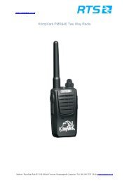
IBe ii,81Is.;EooJ ooU)T8!s"iE,iZtiiat,o3ln= s,Ioo_o{! ICD(r,(Doq)aoo5o3q,=i ocnJoJoN6i i;I+t$r-e:rlsilElsl -:- I i-:i#'t !*EF="'1;iI1l1ll1?r'i?tt??tFRONTllllRE ARIfConnect Systems Inc. - Model TP-163Page 34