MVME177 Single-Board Computer data sheet
MVME177 Single-Board Computer data sheet
MVME177 Single-Board Computer data sheet

You also want an ePaper? Increase the reach of your titles
YUMPU automatically turns print PDFs into web optimized ePapers that Google loves.
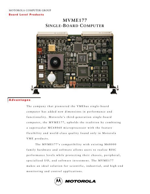
MOTOROLA COMPUTER GROUP<strong>Board</strong> Level Products<strong>MVME177</strong>SINGLE-BOARD COMPUTERAdvantagesThe company that pioneered the VMEbus single-boardcomputer has added new dimensions in performance andfunctionality. Motorola’s third-generation single-boardcomputer, the <strong>MVME177</strong>, upholds the tradition by combininga superscalar MC68060 microprocessor with the featureflexibility and world-class quality found only in MotorolaVME products.The <strong>MVME177</strong>’s compatibility with existing M68000family hardware and software allows users to realize RISCperformance levels while protecting their chassis, peripheral,specialized I/O, and software investment. The <strong>MVME177</strong>makes an ideal solution for scientific, industrial, and high-endmonitoring and control applications.
Features• 50 or 60 MHz MC68060 32-bit microprocessor with8KB of cache, MMU, and FPU• Full 32-bit master/slave VMEbus interface• High-performance DMA, supports VMEbus D64 andlocal bus memory burst cycles• 4, 8, 16, 32, 64, 128 or 256MB on-board DRAM, fourwayinterleaved, with error checking and correction(ECC)• 128KB SRAM with battery backup• On-board SCSI interface with 32-bit local bus burstDMA• On-board Ethernet interface with 32-bit local bus DMA• 4MB of Flash ROM• Two 44-pin sockets for up to 2MB on-boardROM/EPROM• Four EIA-232-D serial ports implemented with quadserial I/O processor• 8-bit, bidirectional, Centronics ® compatible parallel port• Four 32-bit timers and one watchdog timer• 8KB of NVRAM with real-time clock/calendar• Remote Reset/Abort/Status control functions• Completely programmable for maximum integrationflexibility• Low power consumption—less than 20 watts typicalThe Motorola CommitmentMotorola <strong>Computer</strong> Group is committed toproviding best-in-class VME board levelproducts and standard open computerplatforms to the VME industry. Theseproducts provide superior hardware, priceperformance, and faithfulness to the tenets of opencomputing: modularity, scalability, portability, andinteroperability.The <strong>MVME177</strong> adheres to these principles. Becauseof the reliability and quality that are designed intothe <strong>MVME177</strong>, Motorola offers a standard five-yearwarranty. The <strong>MVME177</strong> single-board computeroffers the widest range of flexibility, functionality,and performance available for today’s systemsintegration and OEM marketplace.Ordering InformationPart NumberDescription<strong>MVME177</strong>-001y 50 MHz, 4MB ECC DRAM<strong>MVME177</strong>-002y 50 MHz, 8MB ECC DRAM<strong>MVME177</strong>-003y 50 MHz, 16MB ECC DRAM<strong>MVME177</strong>-004y 50 MHz, 32MB ECC DRAM<strong>MVME177</strong>-005y 50 MHz, 64MB ECC DRAM<strong>MVME177</strong>-006y 50 MHz, 128MB ECC DRAM<strong>MVME177</strong>-011y 60 MHz, 4MB ECC DRAM<strong>MVME177</strong>-012y 60 MHz, 8MB ECC DRAM<strong>MVME177</strong>-013y 60 MHz, 16MB ECC DRAM<strong>MVME177</strong>-014y 60 MHz, 32MB ECC DRAM<strong>MVME177</strong>-015y 60 MHz, 64MB ECC DRAM<strong>MVME177</strong>-016y 60 MHz, 128MB ECC DRAMNote: y indicates product revision level if any; for example, “-001A.”Related ProductsMVME712AFour DB-9 female serial port connectors, one RJ-11connector, Centronics parallel port connector, and P2adapterMVME712BDB-15 Ethernet connector and SCSI connectorMVME712P2P2 adaptor module from VME backplane to cabling fortransition modulesMVME712-012 Same as MVME712A but with DIN connector at P2 foruse with MVME946 chassisRelated DocumentationVME177A/IHV177DIAA/UM68KBUG1/D and68KBUG2/DVMESBCA1/PG andVMESBCA2/PG68-1X7DS<strong>MVME177</strong> Installation and Use manual177Bug diagnostics user’s manualDebugging package user’s manual, volumes 1 and 2Programmer’s reference guide, volumes 1 and 2Includes user’s manuals for each of the peripheralcontrollers used on the <strong>MVME177</strong> seriesNote: Documentation is also available on line at http://www.mcg.mot.com/literature.
VMEbusA32/24:D64/32/16/08Master/SlaveP1P2VMEchip2VMEbusInterfaceEPROM2 Sockets1 Banki82596CAEthernetController53C710SCSICoprocessorCD2401Quad SerialI/O ControllerCentronicsCompatibleParallel I/OPortPCC2ASIC50 or 60 MHzMC68060MPU128KBSRAMw/battery4MBFLASHDataMUXAddressMUXControl4 to 256MBECC DRAMMemory ArrayMK48T08Battery-Backed8KB RAM/ClockBlock DiagramVMEbus InterfaceA significant design advantage of the <strong>MVME177</strong>is the use of a second-generation applicationspecificintegrated circuit (ASIC). The ASICinterfaces the <strong>MVME177</strong> to the VMEbus forhigher levels of quality, reliability, andfunctionality.In addition to controlling the system’s VMEbusfunctions, the VMEbus interface ASIC alsoincludes a local bus to/from VMEbus DMAcontroller, VME board support features, as wellas global control and status register (GCSR) formicroprocessor communications over theVMEbus. The <strong>MVME177</strong> also provides supportfor the VME D64 specification within theVMEbus interface, further enhancing systemperformance.Transition ModulesOptional MVME712 series transition modulesare available to support the use of standard I/Oconnections for the <strong>MVME177</strong> series. Thesemodules take the I/O connections for theperipherals on-board the <strong>MVME177</strong> series fromthe P2 connection of the module to a transitionmodule that has industry standard connections.Expansion MemoryExpansion memory is available for fieldupgrades. Two types of expansion are possible.The first requires replacing the existing memorymezzanine with a new module. The secondrequires the addition of a second mezzaninemodule, requiring a second VMEbus slot.Development SoftwareDevelopment software for the <strong>MVME177</strong> series includes the onboarddebugger/monitor firmware. Object and source code isavailable for application development. Debugger/monitor objectfirmware is included on the board.<strong>MVME177</strong> Memory MapAddress Range Devices Accessed Port Size Size SoftwareCacheInhibit$00000000 toDRAM sizeDRAM size to$FF7FFFFF$FF800000 to$FFBFFFFF$FFC00000 to$FFDFFFFF$FFE00000 to$FFE1FFFF$FFE20000 to$FFEFFFFF$FFF00000 to$FFFEFFFF$FFFF0000 to$FFFFFFFFUser Programmable(On-<strong>Board</strong> DRAM)User Programmable(VMEbus)D32DRAMsizeNotesNo 1, 2D32/D16 3GB No 2, 3, 4EEPROM/Flash D32 4MB No 1Reserved — 2MB — 5SRAM D32 128KB No —SRAM (repeated) D32 896KB No —Local I/O Devices D8-D32 1MB Yes 3User Programmable(VMEbus A16)D32/D16 64KB No 2, 4Notes:1. Flash/EPROM devices appear at $FF800000–$FFBFFFFF and also appear at $0–$3FFFFF ifROM0 bit in VMEchip2 EPROM control register is high (ROM0 = 1). ROM0 is set to 1after each reset. ROM0 bit must be cleared before other resources (DRAM or SRAM) canbe mapped in this range ($0–$3FFFFF). On <strong>MVME177</strong>, the Flash memory is mapped at$0–$3FFFFF by hardware default through VMEchip2.2. This area is user-programmable. The suggested use is shown in the table. The DRAMdecoder is programmed in the MCECC chip, and the local-to-VMEbus and local-to-VSBdecoders are programmed in the VMEchip2.3. Size is approximate.4. Cache inhibit depends on devices in area mapped.5. This area is not decoded. If these locations are accessed and the local bus timer is enabled,the cycle times out and is terminated by a TEA signal.
Specifications<strong>MVME177</strong> <strong>Single</strong>-<strong>Board</strong> <strong>Computer</strong>ProcessorType:Clock Frequency:MemoryMC6806050 MHz or 60 MHzECC Dynamic RAMCapacity:4, 8, 16, 32, 64, 128, 256MBWait States (Read/Write): 3/0Read Burst Mode: 5-1-1-1Write Burst Mode: 2-1-1-1Shared:VMEbus/Local busFlash (120ns)Capacity:4MBAccess Cycles:5-read, 6-writeEPROMSocket Type:44-pin PLCCNumber of Sockets (max. capacity): 2 (256K x 16)Data Width/Capacity:32-bit/2MBVMEbus (IEEE 1014)DTB Master: A16, A24, A32, D08(EO), D16, D32,D64, BLK, UATDTB Slave: A16, A24, A32, D08(EO), D16, D32,D64, BLK, UATArbiter:RR/PRIInterrupt Handler: IRQ 1–7Interrupt Generator: Any 1 of 7System Controller:Yes, jumperableLocation Monitor:4, LMA32SCSI BusController:Asynchronous:Synchronous:Local Bus DMA:EthernetController:Local bus DMA:TOD ClockTOD Clock Device:TimersTimers:Local Bus DMA:Serial Ports53C7105.0MB/s10.0MB/sYes, with local bus bursti82596CAYesController:CD2401Console (EIA-232-D DTE): 4Async Baud Rate, bps max.: 38.4KSync Baud Rate, bps max.:64KM48T08; 8KB NVRAMFour 32-bit, 1 µsec resolutionYesParallel PortsParallel Interface:DimensionsCard Height:Card Depth:Front Panel Height:Front Panel Width:Power Dissipation1 x 8-bit, input, output, control233.4 mm (9.2 in.)160.0 mm (6.3 in.)261.8 mm (10.3 in.)19.8 mm (0.8 in.)Maximum (5V):30 watts+5V ± 5% 6.0A (max.)4.5A (typical @ 50 MHz)+12V ± 10% 1.0A (max., with off-board LANtransceiver)–12V ± 10% 100mA (typical)Hardware SupportMultiprocessing Hardware Support:Debug/Monitor (included):Transition Module (optional):Environmental4 Mailbox interrupts, RMW, sharedRAM<strong>MVME177</strong>FWMVME712 SeriesTemperature (operating):0° C to +55° C, exit air, forced aircoolingTemperature (storage):–40° C to +85° CVibration (non-operating):2 Gs RMS, 20–2000 Hz randomAltitude (operating):15,000 feetHumidity (noncondensing): 5% to 90%SafetyAll printed wiring boards (PWBs) are manufactured with a flammability rating of94V-0 by UL recognized manufacturers.Electromagnetic Compatibility (EMC)Intended for use in systems meeting the following regulations:U.S.: FCC Part 15, Subpart B, Class A (nonresidential)Canada: ICES-003, Class A (nonresidential)This product was tested in a representative system to the following standards:CE Mark per European EMC Directive 89/336/EEC with Amendments; Emissions:EN55022 Class B; Immunity: EN50082-1Demonstrated MTBFMean:190,509 hours90% Confidence: 107,681 hoursKernel and Operating System Software SupportIntegrated Systems, Inc.:pSOS+ Microware Systems Corporation: OS-9 ®Microtec:VRTX32 Lynx Real-Time Systems, Inc.LynxOS Wind River Systems, Inc. VxWorks ®For more information, visit our World Wide Web site at http://www.mcg.mot.comFor fax-back service dial 1-800-682-6128 in the U.S. and 602-438-4636 outside of the U.S.To call us dial 1-800-759-1107 in the U.S. and 512-434-1526 outside of the U.S.Corporate headquarters address: Motorola <strong>Computer</strong> Group, 2900 S. Diablo Way, Tempe, AZ 85282Copyright 1997 Motorola, Inc.Data Sheet: MV177-D5<strong>Computer</strong> GroupMotorola and the Motorola logo are registered trademarks of Motorola, Inc. Centronics is a registered trademark of Centronics Data <strong>Computer</strong> Corporation. All other names, products, and/or servicesmentioned may be trademarks or registered trademarks of their respective holders.This <strong>data</strong> <strong>sheet</strong> identifies products, their specifications, and their characteristics, which may be suitable for certain applications. It does not constitute an offer to sell or a commitment of present or futureavailability, and should not be relied upon to state the terms and conditions, including warranties and disclaimers thereof, on which Motorola may sell products. A prospective buyer should exercise its ownindependent judgement to confirm the suitability of the products for particular applications. Motorola reserves the right to make changes, without notice, to any products or information herein which will, inits sole discretion, improve reliability, function, or design. Motorola does not assume any liability arising out of the application or use of any product or circuit described herein; neither does it convey anylicense under its patent or other intellectual property rights or under others. This disclaimer extends to any prospective buyer, and it includes Motorola’s licensee, licensee’s transferees, and licensee’s customersand users. Availability of some of the products and services described herein may be restricted in some locations.