Assembly: English (GB): 586-536q-eng.pdf - Great Plains ...
Assembly: English (GB): 586-536q-eng.pdf - Great Plains ...
Assembly: English (GB): 586-536q-eng.pdf - Great Plains ...

Create successful ePaper yourself
Turn your PDF publications into a flip-book with our unique Google optimized e-Paper software.
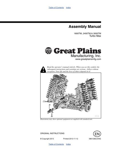
Table of ContentsIndex<strong>Assembly</strong> Manual1800TM, 2400TM & 3000TMTurbo MaxManufacturing, Inc.www.greatplainsmfg.comRead the operator’s manual entirely. When you see this symbol, thesubsequent instructions and warnings are serious - follow withoutexception. Your life and the lives of others depend on it!Illustrations may show optional equipment not supplied with standard unit.43132ORIGINAL INSTRUCTIONSEN© Copyright 2013 Printed 2013-11-12 <strong>586</strong>-536Q-ENGTable of ContentsIndex
Table of ContentsIndexTable of ContentsIndex
<strong>Great</strong> <strong>Plains</strong> Manufacturing, Inc.iiiTable of ContentsImportant Safety Information ......................................1Introduction ..................................................................4Description of Unit ..........................................................4Models Covered .............................................................4Document Family ...........................................................4Tools Required ...............................................................4Pre-assembly Checklist..................................................4Using This Manual..........................................................5Definitions...................................................................5Shipping Inventory..........................................................6Unloading .......................................................................7Unpacking Components .............................................7Unload Smaller Items First .........................................7Unpacking Boxes .......................................................7<strong>Assembly</strong> and Setup Assistance ................................7<strong>Assembly</strong> ......................................................................8Center Frame & Lift <strong>Assembly</strong>....................................8Center Transport 1800 ...............................................9Center Transport 2400-3000 ......................................9Rear Trusses & Fold Brackets..................................10Front Trusses & Level Bar........................................11Valve Brackets & Valves ..........................................12Valve Brackets & Hoses...........................................12Hitch .........................................................................13Wing & Lift <strong>Assembly</strong>................................................14Wing Transport.........................................................15Depth Stop & Angle Gauge .....................................16Attach Hose Clamps and Hose Wraps.....................17Hydraulic Hose Hookup............................................17Hose Handles...........................................................17Purging Hydraulic System ........................................18Center Gang Bar 1800 .............................................20Center Gang Bar 2400-3000 ....................................22Wing Gang Bar 1800-2400.......................................24Wing Gang Bar 3000................................................ 26Front Light <strong>Assembly</strong> ............................................... 28Rear Lights and SMV <strong>Assembly</strong> .............................. 293000 Wing Fold Assist ............................................. 30Proximity Sensor Adjustment ................................... 31Gang Cylinder Purging............................................. 31Hose Routing Hitch .................................................. 32Gauge Wheel (optional) ........................................... 32Rolling Harrow (optional).......................................... 33Reel Following Rolling Harrow (optional) ................. 34Install Rear Hitch (optional)...................................... 35Extended Rear Hitch ................................................ 35A-Frame Hitch .......................................................... 35Rear Stand............................................................... 36Weight Package <strong>Assembly</strong> (Optional)...................... 36Appendix - Reference Information ........................... 38Torque Values Chart.................................................... 38Tire Inflation Chart ....................................................... 39Hydraulic Connectors and Torque ............................... 40Hydraulic Lift Layout .................................................... 421800-2400TM Hydraulic Fold Layout........................... 433000TM Hydraulic Fold Layout .................................... 441800-2400TM Hydraulic Gang Angle Layout............... 453000TM Hydraulic Gang Angle Layout ........................ 461800TM Machine Layout ............................................. 472400TM Machine Layout ............................................. 483000TM Machine Layout ............................................. 491800TM Rolling Harrow Layout ................................... 501800TM Heavy Reel Following Rolling Harrow Layout 512400TM Rolling Harrow Layout ................................... 522400TM Heavy Reel Following Rolling Harrow Layout 533000TM Rolling Harrow Layout ................................... 543000TM Heavy Reel Following Rolling Harrow Layout 55Index........................................................................... 57© Copyright 2006, 2007, 2008, 2009, 2010, 2011, 2012, 2013 All rights Reserved<strong>Great</strong> <strong>Plains</strong> Manufacturing, Inc. provides this publication “as is” without warranty of any kind, either expressed or implied. While every precaution has beentaken in the preparation of this manual, <strong>Great</strong> <strong>Plains</strong> Manufacturing, Inc. assumes no responsibility for errors or omissions. Neither is any liability assumed fordamages resulting from the use of the information contained herein. <strong>Great</strong> <strong>Plains</strong> Manufacturing, Inc. reserves the right to revise and improve its products asit sees fit. This publication describes the state of this product at the time of its publication, and may not reflect the product in the future.Trademarks of <strong>Great</strong> <strong>Plains</strong> Manufacturing, Inc. include: Singulator Plus, Swath Command, Terra-Tine.Registered Trademarks of <strong>Great</strong> <strong>Plains</strong> Manufacturing, Inc. include:Air-Pro, Clear-Shot, Discovator, <strong>Great</strong> <strong>Plains</strong>, Land Pride, MeterCone, Nutri-Pro, Seed-Lok, Solid Stand,Terra-Guard, Turbo-Chisel, Turbo-Chopper, Turbo Max, Turbo-Till, Ultra-Till, Verti-Till, Whirlfilter, Yield-Pro.Brand and Product Names that appear and are owned by others are trademarks of their respective owners.Printed in the United States of America11/12/2013 <strong>586</strong>-536Q-ENG
iv 1800-3000TM <strong>Great</strong> <strong>Plains</strong> Manufacturing, Inc.<strong>586</strong>-536Q-ENG 11/12/2013
<strong>Great</strong> <strong>Plains</strong> Manufacturing, Inc. 1Important Safety InformationLook for Safety SymbolThe SAFETY ALERT SYMBOL indicates there is apotential hazard to personal safety involved and extrasafety precaution must be taken. When you see thissymbol, be alert and carefully read the message that followsit. In addition to design and configuration of equipment,hazard control and accident prevention aredependent upon the awareness, concern, prudence andproper training of personnel involved in the operation,transport, maintenance and storage of equipment.Be Aware of Signal WordsSignal words designate a degree or level of hazard seriousness.DANGER indicates an imminently hazardous situationwhich, if not avoided, will result in death or serious injury.This signal word is limited to the most extreme situations,typically for machine components that, for functional purposes,cannot be guarded.WARNING indicates a potentially hazardous situationwhich, if not avoided, could result in death or seriousinjury, and includes hazards that are exposed wh<strong>eng</strong>uards are removed. It may also be used to alert againstunsafe practices.CAUTION indicates a potentially hazardous situationwhich, if not avoided, may result in minor or moderateinjury. It may also be used to alert against unsafe practices.Use Adequate Lifting MeansThe frame sections and gangs of this machine areextremely heavy. If using multiple lifters, make sure eachis rated for at least its share of the load.> 14,000POUNDSPrepare for Emergencies▲ Be prepared if a fire starts▲ Keep a first aid kit and fire extinguisher handy.▲ Keep emergency numbers for doctor, ambulance, hospitaland fire department near phone.11/12/2013 <strong>586</strong>-536Q-ENG
2 1800-3000TM <strong>Great</strong> <strong>Plains</strong> Manufacturing, Inc.Be Familiar with Safety Decals▲ Read and understand the “Safety Decals” section of theOperators Manual.▲ Read all instructions noted on the decals.▲ Keep decals clean. Replace damaged, faded and illegibledecals.Wear Protective Equipment▲ Wear protective clothing and equipment.▲ Wear clothing and equipment appropriate for the job. Avoidloose-fitting clothing.▲ Because prolonged exposure to loud noise can cause hearingimpairment or hearing loss, wear suitable hearing protectionsuch as earmuffs or earplugs.▲ Because operating equipment safely requires your fullattention, avoid wearing entertainment headphones whileoperating machinery.Avoid High Pressure FluidsEscaping fluid under pressure can penetrate the skin,causing serious injury.▲ Avoid the hazard by relieving pressure before disconnectinghydraulic lines.▲ Use a piece of paper or cardboard, NOT BODY PARTS, tocheck for suspected leaks.▲ Wear protective gloves and safety glasses or goggles whenworking with hydraulic systems.▲ If an accident occurs, seek immediate medical assistancefrom a physician familiar with this type of injury.Use Safety Lights and DevicesSlow-moving tractors and towed implements can createa hazard when driven on public roads. They are difficultto see, especially at night.▲ Use flashing warning lights and turn signals whenever drivingon public roads.▲ Use lights and devices provided with implement.Keep Riders Off MachineryRiders obstruct the operator’s view. Riders could bestruck by foreign objects or thrown from the machine.▲ Never allow children to operate equipment.▲ Keep all bystanders away from machine during operation.<strong>586</strong>-536Q-ENG 11/12/2013
<strong>Great</strong> <strong>Plains</strong> Manufacturing, Inc. Important Safety Information 3Shutdown and Storage▲ Lower implement, put tractor in park, turn off <strong>eng</strong>ine, andremove the key.▲ Secure Turbo Max using blocks and supports provided.▲ Detach and store Turbo Max in an area where children normallydo not play.Tire SafetyTire changing can be dangerous and should be performedby trained personnel using correct tools andequipment.▲ When inflating tires, use a clip-on chuck and extension hoselong enough for you to stand to one side–not in front of orover tire assembly. Use a safety cage if available.▲ When removing and installing wheels, use wheel-handlingequipment adequate for weight involved.Safety At All TimesThoroughly read and understand the instructions in thismanual before operation. Read all instructions noted onthe safety decals.▲ Be familiar with all machine functions.▲ Operate machinery from the driver’s seat only.▲ Do not leave machine unattended with tractor <strong>eng</strong>ine running.▲ Do not stand between the tractor and machine duringhitching.▲ Keep hands, feet and clothing away from power-drivenparts.▲ Wear snug-fitting clothing to avoid entanglement with movingparts.▲ Watch out for wires, trees, etc., when folding and raisingmachine. Make sure all persons are clear of working area.11/12/2013 <strong>586</strong>-536Q-ENG
4 1800-3000TM <strong>Great</strong> <strong>Plains</strong> Manufacturing, Inc.IntroductionThe Turbo Max has been designed with care and built byskilled workers using quality materials. Proper setup,maintenance, and safe operating practices will help thecustomer get years of satisfactory use from the machine.Description of UnitThe 1800-3000TM Turbo Max is a three section “vertical”tillage tool. Working width ranges from 18 to 30 feet. Theimplement is designed to cut and size residue, till soil forfaster seedbed warming, break up soil crust on hard driedfields while eliminating compaction layers. The front andrear gangs may be adjusted from 0-6 degree angle,depending on the aggressiveness desired. Various finishingattachments are also available to further smooth,redistribute residue, kill weeds, and break clods.Models Covered1800TM2400TM3000TM18’ (7.5in) spacing24’ (7.5in) spacing30’ (7.5in) spacingFigure 12400 Turbo Max43133Document Family<strong>586</strong>-536Q Pre-Delivery Manual<strong>586</strong>-536M Operator Manual<strong>586</strong>-536P Parts Manual<strong>586</strong>-536Q-ENG <strong>Assembly</strong> Manual (this document)Tools Required• Basic Hand Tools• Torque Wrench• Fork Truck, Overhead Hoist or LoaderPre-assembly Checklist❑❑❑❑❑Before assembling, read and understand “ImportantSafety Information” in front part of this manual.Have at least two people on hand while assembling.Make sure area is level and free of obstructions (preferablyan open concrete area).Have all major componentsHave all fasteners and pins shipped with machine.<strong>586</strong>-536Q-ENG 11/12/2013
<strong>Great</strong> <strong>Plains</strong> Manufacturing, Inc. Introduction 5Using This ManualThis manual was written to help you assemble and preparethe new machine for the customer. The manualincludes instructions for assembly and setup. Read thismanual and follow the recommendations for safe, efficientand proper assembly and setup.An operator’s and parts manual is also provided with thenew machine. Read and understand “Important SafetyInformation” and “Operating Instructions” in the operator’smanual before assembling the machine. Refer to theparts manual for proper part’s identification. As a reference,keep the operator’s and part’s manual on hand whileassembling.The information in this manual is current at printing. Someparts may change to assure top performance.DefinitionsThe following terms are used throughout this manual.A crucial point of information related to the preceding topic. Readand follow the directions to remain safe, avoid serious damage toequipment and ensure desired field results.Note: Useful information related to the preceding topic.RLFigure 2Right / Left43133Right-hand and left-hand as used inthis manual are determined by facingthe direction the machine will travelwhile in use unless otherwise stated.An orientation rose in some line artillustrations shows the directions of: Up,Back, Left, Down, Front, Right.RFUDBL11/12/2013 <strong>586</strong>-536Q-ENG
6 1800-3000TM <strong>Great</strong> <strong>Plains</strong> Manufacturing, Inc.Shipping InventoryThe machine will be shipped unassembled as shown ina big shipping rack and shipping boxes on pallets. Theonly parts that will be assembled are the gang assemblies,reel and rolling harrow attachment assemblies.Refer to Figure 3• All frame sections, hitch and torque tubes will beshipped in shipping container rack.• Small parts and bolts will be shipped in boxes.Refer to Figure 4• Rear attachments and gang assemblies will beshipped in shipping container rack.• Shipping containers or racks do not need to bereturned to <strong>Great</strong> <strong>Plains</strong>.Figure 3Shipping Rack & Box42967Figure 4Shipping Gangs & Attachments42968<strong>586</strong>-536Q-ENG 11/12/2013
<strong>Great</strong> <strong>Plains</strong> Manufacturing, Inc. Introduction 7UnloadingOnce everything is unloaded from “storage pod” you mayproceed with taking parts out of shipping containers.Carefully move everything to level site and prepare to unpack items.Unpacking ComponentsBe sure you have read and understood the ImportantSafety Information, starting on page 1 of this manual,before you start unpacking components.Centering components:Be sure and center fork truck or chains (overhead hoist)on components so they won’t slide and cause injury.Carefully un-band components.Now unload individual components one at a time using afork truck or overhead hoist.Move each component out of the way so you have plentyof room to remove the next one.Unload Smaller Items FirstUnloading the frames is a potentially dangerous operation.Reduce risk and complication by first unloading1. the tire wheel assemblies,2. the smaller itemsPlace these components well out of the maneuveringarea needed for unloading the gang assemblies andframes.3. Carefully unload the frames and hitch out of shippingrackUnpacking Boxes1. Carefully remove banding and lids from boxes.2. Locate and identify all components before assembling.<strong>Assembly</strong> and Setup AssistanceTo order additional copies of pre-delivery instructions oroperator’s and parts manuals, write to the followingaddress. Include model numbers in all correspondence.If you do not understand any part of this manual or haveany assembly or setup questions, assistance is available.Contact:Product Support<strong>Great</strong> <strong>Plains</strong> Mfg. Inc., Service DepartmentPO Box 5060Salina, KS 67402-5060(800)255-921511/12/2013 <strong>586</strong>-536Q-ENG
8 1800-3000TM <strong>Great</strong> <strong>Plains</strong> Manufacturing, Inc.<strong>Assembly</strong>Center Frame & Lift <strong>Assembly</strong>Refer to Figure 5Note: Once the center frame has been uncrated and puton stands, the brace bar may be installed. See“Parts Manual” for part numbers and description ofparts.3. Align holes in plates of the center brace bar 1 withholes on front of center frame 2 , secure with 3/4 x 2hex bolts 3 , 3/4 lock washers and 3/4 nuts.4. Carefully lower the torque tube 4 (models 2400 or3000) or torque tube 5 (model 1800) with an overheadhoist until holes are aligned with the holes ontop of center frame 2 and secure with 1 1/4 x 7 pins6 , 3/8 x 2 1/4 Gr. 8, special thread bolts 7 and 3/8top lock nuts.5. Align hole in lift strap 8 and cylinder mount plate 9in proper orientation shown in drawing. Secure liftstrap 8 with 1 x 3 1/2 hex bolts 10 and 1 lock nuts,rear of cylinder mount plate 9 to plates of torquetube 4 or 5 with 1 x 4 hex bolt 11 and 1 lock nut.6. Install the cylinders 12 using 1 x 3 1/8 pins 13, 1.5 x1.0 x.075 machine washers and 3/16 x 2 cotter pin.7. Install cylinder transport locks 14 to cylinders 12using 3/8 x 3 pins 15 and clip pins8. Tighten all bolts with lock nuts snug, but do nottorque. The rest of the bolts may be tightened tospecs, See “Torque Values Chart” on page 38.RFUDBL1341514101312891153106712Figure 5Center Frame & Lift <strong>Assembly</strong> 42951<strong>586</strong>-536Q-ENG 11/12/2013
<strong>Great</strong> <strong>Plains</strong> Manufacturing, Inc. <strong>Assembly</strong> 9Center Transport 1800Refer to Figure 69. Slide hub/spindle assembly 1 into torque tube 2 andalign holes. Secure with 1/2 x 4 1/2 hex bolts 3 and 1/2top lock nut.10. Attach tire/wheel assembly 4 with 5/8 lug nuts 5 .11. Tighten all bolts with lock nuts snug, but do not torque.The rest of the bolts may be tightened to specs, See“Torque Values Chart” on page 38.3425RUB1FDLFigure 6Center Transport 180042952Center Transport 2400-3000Refer to Figure 712. Slide walking beam assembly 1 into torque tube 2 andalign holes. Secure with 1/2 x 6, Gr. 8 hex bolts 3 and 1/2 top lock nut.2313. Slide hub/spindle assemblies 4 into walking beamassembly 1 and align holes. Secure with 1/2 x 5 hexbolts 5 and 1/2 top lock nut.14. Attach tire/wheel assemblies 6 with 5/8 lug nuts 7 .15. Tighten all bolts with lock nuts snug, but do not torque.The rest of the bolts may be tightened to specs, See“Torque Values Chart” on page 38.RFUDBL144567Figure 7Center Transport 2400-30004295311/12/2013 <strong>586</strong>-536Q-ENG
10 1800-3000TM <strong>Great</strong> <strong>Plains</strong> Manufacturing, Inc.Rear Trusses & Fold BracketsRefer to Figure 816. Attach rear truss bars 1 to plates on center framewith 3/4 x 2 1/2 hex bolt 2 (front plate), 3/4 x 2 hexbolt 3 (rear plate), 3/4 lock washers and 3/4 nuts.17. Install front and rear (model 3000 only) fold brackets4 with 3/4 x 2 hex bolt 3 (rear plate), 3/4 lock washersand 3/4 nuts.18. Install double block tees 5 in locations shown belowwith 5/16 x 5 1/2 hex bolt 6 , 5/16 x 2 1/2 hex bolt 7 ,5/16 x 4 hex bolt 8 , 5/16 lock washers and 5/16nuts.19. Attach outside plates of wing stops 9 with 5/8 x 1 1/2 hex bolts 10, 5/8 lock washers and 5/8 nuts.Secure inside plate to rear truss bars 1 with 5/8 x 41/32 x 5 1/2 u-bolts 11, 5/8 lock washers and 5/8nuts.20. Attach 3/4 x 3 hitch pin 12 to tube wing stops 9 .21. Bolts may be tightened to specs, See “Torque ValuesChart” on page 38 and all cotter pins may bebent.RFUDBL910512719583465234311Figure 8Rear Trusses & Fold Brackets 42956<strong>586</strong>-536Q-ENG 11/12/2013
<strong>Great</strong> <strong>Plains</strong> Manufacturing, Inc. <strong>Assembly</strong> 11Front Trusses & Level BarRefer to Figure 922. Install rear level bar 1 to torque tube with 1 x 9 1/2pins 2 , 3/8 x 2 1/4, Gr. 8 hex bolts 3 and 3/8 nylonlock nut.23. Install h-bracket assembly 4 to front of rear level bar1 with 3/4 x 2, Gr. 8 hex bolts 5 , 3/4 lock washersand 3/4 nuts.24. Install bottom of h-bracket assembly 4 to centerbrace bar with 1 x 3 1/4 clevis pin 6 , 1.5 x 1.00x.075 machine washer 7 and 3/16 x 2 cotter pin.25. Attach front hitch trusses 8 with 3/4 x 2 hex bolt 9(front plate), 3/4 x 2 1/2 hex bolt 10 (rear plates), 3/4lock washers and 3/4 nuts.26. Tighten all bolts with lock nuts snug, but do nottorque. The rest of the bolts may be tightened tospecs, See “Torque Values Chart” on page 38.RUBFDL534128109678Figure 9Front Trusses & Level Bar 4295711/12/2013 <strong>586</strong>-536Q-ENG
12 1800-3000TM <strong>Great</strong> <strong>Plains</strong> Manufacturing, Inc.Valve Brackets & ValvesRefer to Figure 10Note: Bolts needed in these next steps will be bolted on partsor located in a bag on front of center frame.27. Remove the 1/2 x 3 1/32 x 6 u-bolts 4 from the valvebrackets 1 and 2 , Attach bypass and counterbalancevalve bracket 1 and lock valve bracket 2 to center bracebar 3 in proper locations, shown, See “Valve Brackets &Hoses” below, with the same 1/2 x 3 1/32 x 6 u-bolts 4 , 1/2 lock washers and 1/2 nuts.28. Be sure hoses are routed as shown in, See “Valve Brackets& Hoses” below.29. Install bypass valve 5 on top of valve bracket 1 with 5/16x 3 Gr. 5 hex bolts 6 , 5/16 lock washers and 5/16 nuts.30. Fasten the counter balance valve 7 to side of valvebracket 1 with 5/16 x4Gr.5hexbolts 8 , 5/16 lock washersand 5/16 nuts.31. Install the lock valve 9 to the top of the valve bracket 2with 1/4 x 2 Gr. 5 hex bolts 10, 1/4 lock washers and 1/4nuts.32. Fasten the two way fold valve 11 to top of plate on tube ofcenter brace bar 3 with 5/16 x 1 3/8 x 2 3/16 u-bolts 12and 5/16 top lock nuts.33. Attach depth control valve 13 to top of depth stop bracket(plunger forward), with 5/16 x 2 Gr. 5 hex bolts 14 and 5/16 lock washers.34. Bolts may be tightened to specs, See “Torque ValuesChart” on page 38.Valve Brackets & HosesRefer to Figure 11Note: The hoses will be shipped hooked up to valves and cylinders.The front valves and hoses (that will need routedthrough front brace bar, trusses and up hitch totractor) will be rolled up and tied to front of center frameduring shipping. The wing fold two way 1 , bypass 2and lock valves 3 will need mounted in proper locationas shown and hoses routed correctly before front trusses4 and hitch are installed so front weight kits may beinstalled or removed without taking hoses or valvesloose. The hoses need to route in locations shown witharrows, on top of wing brace 5 to outside of tubes thenback to inside. Install front trusses 4 on top of hoses asshown. The two valve plates will be mounted in correctlocation but will need turned around 180 degrees ontube so they are facing forward on machine. Set them1” from truss plates as shown. See “Valve Brackets &Valves” above, for proper mounting instructions.28UR B 7FDL101916534Figure 10Valve Brackets & Valves2314134 45111243113Figure 11Valve Brackets & Hoses43112<strong>586</strong>-536Q-ENG 11/12/2013
<strong>Great</strong> <strong>Plains</strong> Manufacturing, Inc. <strong>Assembly</strong> 13HitchRefer to Figure 1235. Bolt the hitch frame 1 to front trusses with the 1 1/4x 8 Gr. 8 bolts 2 , 1 1/4 flat washer 3 (one side ofuniball to take up space) and 1 1/4 top lock nuts.Tighten bolts snug, do not torque, as the hitch mustpivot freely.36. Install jack 4 on front outside of hitch to support thefront of hitch 1 for the rest of assembly.37. Attach h-bracket in orientation shown below with 1 x2 29/64 clevis pins 6 , 1.5 x 1.00 x 0.075 machinewashers and 3/16 x 2 cotter pins.38. Attach level bar tube 7 with 1 1/4 x 8 1/2 Gr. 8 specialthread bolts 8 , rear bolt from left side, front boltfrom right side and secure with 1 1/4 top lock nuts.39. Attach rear of level turnbuckle 10 with 1 x 8 Gr. 8special thread bolt 9 , front with 1 x 6, Gr. 8 specialthread bolt 11 and 1 top lock nuts.40. Attach two, 1 3/4 gang wrenches 12 and one, 2 5/16-1 15/16 turnbuckle wrench 13 over pegs on back ofhitch, secure with 3/16 w/cotter/chain 14.41. Install the spring hose holder 15 to welded nut onfront of hitch with 1/2 x 1 Gr. 5 bolt 16, 1/2 lockwasher and 1/2 flat washer.42. Align holes in hitch base 17 with holes on front ofhitch frame 1 . Align holes of safety chain support 18in orientation shown, secure with two, 1 x 8 Gr. 8special thread bolts 9 , six, 1 flat washers 19 (4 rightside, 2 left side), 1 lock washers and 1 nuts.43. Attach safety chain 20 to bottom side of hitch frame1 , secure with 7/8 x 3 hex bolt 21, 7/8 flat washer, 7/8 lock washer and 7/8 nut.44. Mount manual pack 22 with 1/4 x 1 hex bolts 23, miniend wheel press wheels 24, 1/4 lock washers and 1/4 nuts.45. Tighten all bolts with lock nuts snug, but do nottorque. The rest of the bolts may be tightened tospecs, See “Torque Values Chart” on page 38.22102324715218616591431213821718201991411RFUDBLFigure 12Hitch 4295811/12/2013 <strong>586</strong>-536Q-ENG
14 1800-3000TM <strong>Great</strong> <strong>Plains</strong> Manufacturing, Inc.Wing & Lift <strong>Assembly</strong>Refer to Figure 1346. Attach wing brace 1 to wing frame 2 with 3/4 x 2hex bolts 3 , 3/4 lock washers and 3/4 nuts.47. Attach wing brace 1 and wing frame 2 to centerframe with wing hinge pins 4 , 1 1/4 flat washers 5(rear side of wing hinge tubes only, do not usewasher on wing brace bar) and 1 lock nuts.48. Install lh and rh wing wheel arms 6 with 1 x 7 pins7 , 3/8 x 2 1/4, Gr. 8, special thread hex bolts 8 and3/8 nylon lock nut.Note: Be sure turnbuckle assembly 9 is preset at 45 3/4” before installing as shown below. See gangangle adjustment in “Operator Manual” beforegoing to field.49. Install wing wheel turnbuckles 9 to front, top hole, ofcylinder mount plate 10 with 1 x 4 hex bolts 11 and 1lock nuts.50. Install rear hole of cylinder mount plate 10 to insideof plates of wing wheel arms 6 with 1 x 4 hex bolts11 and 1 lock nuts.51. Secure front of wing wheel turnbuckles 9 to plate onwing frame 2 with 1x4hexbolts 11 and 1 lock nuts.52. Install wing lift cylinders 12 (base end to cylindermount plate 10) with 1 x 3 1/8 pins 13, 1.5 x 1.0x.075 machine washers and 3/16 x 2 cotter pin.53. Attach wing stop brackets 14 to plate of wing frame2 with 5/8 x 1 1/2 hex bolts 15, 5/8 lock washers and5/8 nuts.54. Now the base end of fold cylinders 16 may behooked up with the 1 x 3 1/8 clevis pin 13, 1.5 x 1.00x 0.075 machine washer and 3/16 x 2 cotter pin.55. Do not hook up rod end of fold cylinder 16 until systemis purged of air. See “Purging Hydraulic System”on page 18.56. Tighten all bolts with lock nuts snug, but do nottorque. The rest of the bolts may be tightened tospecs, See “Torque Values Chart” on page 38.1613161110612911 11514513413152Figure 13Wing & Lift <strong>Assembly</strong> 4295978RFUDBL<strong>586</strong>-536Q-ENG 11/12/2013
<strong>Great</strong> <strong>Plains</strong> Manufacturing, Inc. <strong>Assembly</strong> 15Wing TransportNote: Model 1800 does not use tire/wheel on inside of wheelarm.Refer to Figure 1457. Slide hub/spindle assembly 1 into torque tube 2 andalign holes. Secure with 5/16 x 3 1/2 hex bolts 3 and 5/16 top lock nut.RFUDBL3458. Attach tire/wheel assembly 4 with 5/8 lug nuts 5 .59. Tighten all bolts with lock nuts snug, but do not torque.The rest of the bolts may be tightened to specs, See“Torque Values Chart” on page 38.215Figure 14Wing Transport4296011/12/2013 <strong>586</strong>-536Q-ENG
16 1800-3000TM <strong>Great</strong> <strong>Plains</strong> Manufacturing, Inc.Depth Stop & Angle GaugeRefer to Figure 15Note: See machine layout drawings in Appendix forproper gang gauge placement for each model.60. Slide depth stop tube 1 from rear of machine underleft wing stop through square hole on depth controlbracket on center wing brace. Align rear holes overlever on torque tube, secure with 1/2 x 3 hex bolt 2 ,1/2 top lock nut.61. Fasten depth stop assembly 3 on top of depth stoptube with 1/2 x 2 1/2 hex bolts 4 , 1/2 lock washersand nuts.62. Attach angle gauge bracket assembly 5 to front ofcenter frame with 1/2 x 3 1/32 x 6 u-bolts 6 , 1/2 lockwashers and 1/2 nuts.63. Attach gauge link 7 to ear on front of center frameand gauge bracket assembly 5 , secure with 3/8 x 11/4 hex bolts 8 and 3/8 top lock nuts.64. Tighten all bolts with lock nuts snug, but do nottorque. The rest of the bolts may be tightened tospecs, See “Torque Values Chart” on page 38.2RUB1FDL34785 6Figure 15Depth Stop & Angle Gauge 42971<strong>586</strong>-536Q-ENG 11/12/2013
<strong>Great</strong> <strong>Plains</strong> Manufacturing, Inc. <strong>Assembly</strong> 17Attach Hose Clamps and Hose WrapsNote: Refer to hydraulic layouts in “Appendix” section of thismanual for proper lift and fold hose routing on centerand wings. Do not clamp hoses on hitch until gang hosesare hooked up, See “Gang Cylinder Purging” onpage 31. See “Hydraulic Connector ID” on page 40for proper fitting installation.Refer to Figure 1665. When all the lift and fold hoses are hooked up and tightenedproperly, put hose clamps on hoses as shown.66. Install hose wraps on hoses as needed.Note: Be sure and get hoses and light wiring harness fastenedproperly so they do not drag. Check to be surethere is enough slack in hinge area when folding machinethe first time.Figure 1641583Hose Clamp <strong>Assembly</strong>Hydraulic Hose Hookup67. <strong>Great</strong> <strong>Plains</strong> hydraulic hoses are color coded to help youhookup hoses to your tractor outlets. Hoses that go to High Pressure Fluid Hazard:the same remote valve are marked with the same color. Relieve pressure before disconnecting hydraulic lines. Usepaper or cardboard, NOT BODY PARTS, to check for leaks.ColorHydraulic FunctionWear protective gloves and safety glasses or goggles whenBlack Lift (2 hoses)working with hydraulic systems. Escaping fluid under pressurecan have sufficient pressure to penetrate the skin causing seriousinjury. If an accident occurs, seek immediate medicalGreen Fold (2 hoses)Red Gang Adjustment (2 hoses)assistance from a physician familiar with this type of injury.Only trained personnel should work on system hydraulics.Hose HandlesRefer to Figure 1768. To distinguish hoses on the same hydraulic circuit, referto hose handles. The hose under an extended-cylindersymbol feeds a cylinder base end. The hose under aretracted-cylinder symbol feeds a cylinder rod end.69. Once all hoses are tightened, hook hoses to tractor.Figure 17Hose Handles4155211/12/2013 <strong>586</strong>-536Q-ENG
18 1800-3000TM <strong>Great</strong> <strong>Plains</strong> Manufacturing, Inc.Purging Hydraulic SystemNote: When lift and fold hoses are routed and hookedup to cylinders and valves the systems will needpurged of air. Purging the lift and fold system nowRefer to Figure 1870. Charge the lift system first. Extend the lift cylinders 1(black handles) until the center section is fully raised.Remove the cylinder transport locks 2 and store onlift straps 3 . Raise and lower the lift system severaltimes to purge air from system. Watch for leaks andretighten fittings if necessary.71. You may now charge the fold system. Before chargingthe fold cylinders 4 , make sure the rod end of thecylinders are un-bolted or un-pinned and block 6 iswill allow the wings to be folded and unfolded. Themachine may also be raised up or down for easeof gang assembly installation.placed under cylinders as shown, so that when therod is extended, it will clear the wing fold brackets.Extend the fold cylinders 4 (green ends) completelyand then close them. Extend and retract the cylindersseveral times to purge air from the system.72. Now the rod end of fold cylinders 4 may be hookedup to wing with the 1 x 3 1/8 usable pin 5 , 1.5 x 1.0x.075 machine washer and 3/16 x 2 cotter pin. Bendcotter pin over to secure.<strong>586</strong>-536Q-ENG 11/12/2013
<strong>Great</strong> <strong>Plains</strong> Manufacturing, Inc. <strong>Assembly</strong> 19RFUDBL41264342165Figure 18Purging Hydraulic System 4312811/12/2013 <strong>586</strong>-536Q-ENG
20 1800-3000TM <strong>Great</strong> <strong>Plains</strong> Manufacturing, Inc.Center Gang Bar 1800Note: Refer to center gang bar assembly in “Parts Manual”for correct part numbers of all components.Refer to Figure 1973. Position gang assemblies 1 in proper locations.Install the gang pivot bolt 2 through tubes of gangbars and tubes on center frame, secure with 1 1/4flat washers 3 (one on top and one on bottom), 1 1/4 slotted nut 4 (one on top and one on bottom).Tighten bolts snug, torque to 350 to 400ft-lbs. Installthe 3/16 x 2 cotter pins 5 through 1 1/4 slotted nuts4 and bend over to secure.Note: Be sure turnbuckle assembly 6 is preset at 62”before installing as shown below. See gang angleadjustment in “Operator Manual” before going tofield.74. Install turnbuckle assembly 6 , adjustable end on earon front of rear gang bars and fixed end on ear offront gang bars. Secure with 1 x 3 1/4 clevis pin 7 ,1.5 x 1.00 x 0.075 machine washer 8 and 3/16 x 2cotter pin 5 .Refer to machine layout drawings in this manualfor correct gang assembly placement.75. Install the round tubes 11 (two on each gang bar)between bottom front plate 9 (slotted hole towardrear), rear plates 10 and plates on center frame.Install the 3/4 x 6 hex bolts 12, 3/4 lock washers and3/4 nuts. Attach other ends of plates 9 and 10 tobottom of center frame with 3/4 x 2 hex bolts 13 and3/4 lock washers.76. Install bracket 14 on bottom side of gang bar plate,secure with 5/8 x 3 1/2 hex bolts 15, 5/8 lock washersand 5/8 nuts.77. Now the gang cylinders 16 may be hooked up withthe 1 x 3 1/8 clevis pin 17, 1.5 x 1.00 x 0.075machine washer 8 and 3/16 x 2 cotter pin 5 .78. Bolts may be tightened to specs, See “Torque ValuesChart” on page 38 and all cotter pins may bebent.<strong>586</strong>-536Q-ENG 11/12/2013
<strong>Great</strong> <strong>Plains</strong> Manufacturing, Inc. <strong>Assembly</strong> 21RFUDBL161243521521511215714176116511381131084139Figure 19Center Gang Bar 1800 4295411/12/2013 <strong>586</strong>-536Q-ENG
22 1800-3000TM <strong>Great</strong> <strong>Plains</strong> Manufacturing, Inc.Center Gang Bar 2400-3000Note: Refer to center gang bar assembly in “Parts Manual”for correct part numbers of all components.Refer to Figure 2079. Position gang assemblies 1 in proper locations.Install the gang pivot bolt 2 through tubes of gangbars and tubes on center frame, secure with 1 1/4flat washers 3 (one on top and one on bottom), 1 1/4 slotted nut 4 (one on top and one on bottom).Tighten bolts snug, torque to 350 to 400ft-lbs. Installthe 3/16 x 2 cotter pins 5 through 1 1/4 slotted nuts4 and bend over to secure.Note: Be sure turnbuckle assembly 9 is preset at 30 1/4” before installing as shown below. See gangangle adjustment in “Operator Manual” beforegoing to field.80. Install rocker arm 6 to tube on center frame with 1 1/4 x 10 special thread bolt 7 , secure with 1 1/4 toplock nut.81. Install link 8 with 1 x 3 1/4 clevis pin 10, 1.5 x 1.00 x0.075 machine washer 11 and 3/16 x 2 cotter pin 5 .82. Install turnbuckle assembly 9 , adjustable end on earon front of rear gang bars and fixed end on rear ofrocker arm 6 . Secure with 1 x 3 1/4 clevis pin 10, 1.5x 1.00 x 0.075 machine washer 11 and 3/16 x 2 cotterpin 5 .Refer to machine layout drawings in this manualfor correct gang assembly placement.83. Install the round tubes 14 (two on each gang bar)between bottom front plate 12 (slotted hole towardrear), rear plates 13 and plates on center frame.Install the 3/4 x 6 hex bolts 15, 3/4 lock washers and3/4 nuts. Attach other ends of plates 12 and 13 tobottom of center frame with 3/4 x 2 hex bolts 15 and3/4 lock washers.84. Install bracket 16 on bottom side of gang bar plate,secure with 5/8 x 3 1/2 hex bolts 17, 5/8 lock washersand 5/8 nuts.85. Now the gang cylinders 18 may be hooked up withthe 1 x 3 1/8 clevis pin 19, 1.5 x 1.00 x 0.075machine washer 11 and 3/16 x 2 cotter pin 5 .86. Hook gang cylinder hoses to gang cylinders, be sureall fittings are tightened to specs, See “HydraulicConnector ID” on page 40. Now the gang systemmay be purged of air, See “Purging Hydraulic System”on page 19.87. Bolts may be tightened to specs, See “Torque ValuesChart” on page 38 and all cotter pins may bebent.<strong>586</strong>-536Q-ENG 11/12/2013
<strong>Great</strong> <strong>Plains</strong> Manufacturing, Inc. <strong>Assembly</strong> 23RUB1534FDL1925117721511751010869161191851111413154314111512Figure 20Center Gang Bar 2400-3000 4295511/12/2013 <strong>586</strong>-536Q-ENG
24 1800-3000TM <strong>Great</strong> <strong>Plains</strong> Manufacturing, Inc.Wing Gang Bar 1800-2400Note: Refer to center gang bar assembly in “Parts Manual”for correct part numbers of all components.Refer to Figure 2188. Position gang assemblies 1 in proper locations.Install the gang pivot bolt 2 through tubes of gangbars and tubes on center frame, secure with 1 1/4flat washers 3 (one on top and one on bottom), 1 1/4 slotted nut 4 (one on top and one on bottom).Tighten bolts snug, torque to 350 to 400ft-lbs. Installthe 3/16 x 2 cotter pins 5 through 1 1/4 slotted nuts4 and bend over to secure.Note: Be sure turnbuckle assembly 6 is preset at 62”before installing as shown below. See gang angleadjustment in “Operator Manual” before going tofield.89. Install turnbuckle assembly 6 , adjustable end on earon front of rear gang bars and fixed end on ear offront gang bars. Secure with 1 x 3 1/4 clevis pin 7 ,1.5 x 1.00 x 0.075 machine washer 8 and 3/16 x 2cotter pin 5 .90. Install the round tubes 11 (two on each gang bar)between bottom front plate 9 (slotted hole towardRefer to machine layout drawings in this manualfor correct gang assembly placement.rear), rear plates 10 and plates on wing frame. Installthe 3/4 x 6 hex bolts 12, 3/4 lock washers and 3/4nuts. Attach other ends of plates 9 and 10 to bottomof wing frame with 3/4 x 2 hex bolts 13 and 3/4 lockwashers.91. Install bracket 14 on bottom side of gang bar plate,secure with 5/8 x 3 1/2 hex bolts 15, 5/8 lock washersand 5/8 nuts.92. Now the gang cylinders 16 may be hooked up withthe 1 x 3 1/8 clevis pin 17, 1.5 x 1.00 x 0.075machine washer 8 and 3/16 x 2 cotter pin 5 .93. Hook gang cylinder hoses to gang cylinders, be sureall fittings are tightened to specs, See “HydraulicConnector ID” on page 40. Now the gang systemmay be purged of air, See “Purging Hydraulic System”on page 19.94. Bolt may be tightened to specs, See “Torque ValuesChart” on page 38 and all cotter pins may be bent.<strong>586</strong>-536Q-ENG 11/12/2013
<strong>Great</strong> <strong>Plains</strong> Manufacturing, Inc. <strong>Assembly</strong> 2512342RFUDBL1515212576141781116118101334811139Figure 21Wing Gang Bar 1800-2400 4296111/12/2013 <strong>586</strong>-536Q-ENG
26 1800-3000TM <strong>Great</strong> <strong>Plains</strong> Manufacturing, Inc.Wing Gang Bar 3000Note: Refer to center gang bar assembly in “Parts Manual”for correct part numbers of all components.Refer to Figure 2295. Position gang assemblies, front 1 and rear 2 inproper locations. Install the gang pivot bolt 3through tubes of gang bars and tubes on centerframe, secure with 1 1/4 flat washers 4 (one on topand one on bottom), 1 1/4 slotted nut 5 (one on topand one on bottom). Tighten bolts snug, torque to350 to 400ft-lbs. Install the 3/16 x 2 cotter pins 6through 1 1/4 slotted nut 5 and bend over to secure.Note: Be sure turnbuckle assembly 7 is preset at 62”before installing as shown below. See gang angleadjustment in “Operator Manual” before going tofield.96. Install turnbuckle assemblies 7 , adjustable end onear on front of rear gang bars and fixed end on ear offront gang bars. Secure with 1 x 3 1/4 clevis pin 8 ,1.5 x 1.00 x 0.075 machine washer 9 and 3/16 x 2cotter pin 6 .97. Install the round tubes 12 (two on each gang bar)between bottom front plate 10 (slotted hole towardrear), rear plates 11 and plates on wing frame. InstallRefer to machine layout drawings in this manualfor correct gang assembly placement.the 3/4 x 6 hex bolts 13, 3/4 lock washers and 3/4nuts. Attach other ends of plates 10 and 11 to bottomof wing frame with 3/4 x 2 hex bolts 14 and 3/4 lockwashers.98. Install bracket 15 on bottom side of gang bar plate,secure with 5/8 x 3 1/2 hex bolts 16, 5/8 lock washersand 5/8 nuts.99. The 3.50 x 2.5 x 1.25 gang cylinders 17 and 3.25 x2.5 x 1.25 gang cylinders 18 may be hooked up withthe 1 x 3 1/8 clevis pin 19, 1.5 x 1.00 x 0.075machine washer 9 and 3/16 x 2 cotter pin 6 .100.Hook gang cylinder hoses to gang cylinders, be sureall fittings are tightened to specs, See “HydraulicConnector ID” on page 40. Now the gang systemmay be purged of air, See “Purging Hydraulic System”on page 19.101.Bolt may be tightened to specs, See “Torque ValuesChart” on page 38 and all cotter pins may be bent.<strong>586</strong>-536Q-ENG 11/12/2013
<strong>Great</strong> <strong>Plains</strong> Manufacturing, Inc. <strong>Assembly</strong> 27133451613RFUD5BL13431316219798171 768152541914181210121114Figure 22Wing Gang Bar 3000 4296211/12/2013 <strong>586</strong>-536Q-ENG
28 1800-3000TM <strong>Great</strong> <strong>Plains</strong> Manufacturing, Inc.Front Light <strong>Assembly</strong>Refer to Figure 23102.Fasten LH 1 and RH 2 light brackets to centerbrace bar with 1/2 x 3 1/32 x 6 u-bolts 3 , 1/2 lockwashers and 1/2 huts.103.Route light harness lead w/valve 4 from front ofhitch (tractor plug to front), along same route ashydraulic hose (fasten in same clamps and hosewraps as hoses) to center brace bar. Plug one end ofenhance light harness 5 to small end of light harnesslead w/valve 4 . Plug bigger end of light harnessdual amber 6 into other end of enhance lightmodule 5 . Route shorter leads over towards(marked left and right) the front light mounting bracketsas shown. Route long lead 6 along hoses oncenter frame tube to rear of machine. This lead willbe hooked up as shown in, See “Rear Lights &SMV” on page 29.104.Mount amber lamp lights 7 to top of light brackets 1and 2 , with 1/4 x 1 Gr. 5 hex bolts 8 and 1/4 locknuts. Plug lead of amber lamp lights 7 into leads oflight harness dual amber 6 .105.Tighten all bolts with lock nuts snug, but do nottorque. The rest of the bolts may be tightened tospecs, See “Torque Values Chart” on page 38. Besure and get all wiring harnesses fastened upsecurely with hose wraps or clamps (if routed closeto hydraulic hoses) or use cable ties 9 .867 32949<strong>586</strong>1674RUBFDLFigure 23Front Lights 43234<strong>586</strong>-536Q-ENG 11/12/2013
<strong>Great</strong> <strong>Plains</strong> Manufacturing, Inc. <strong>Assembly</strong> 29Rear Lights and SMV <strong>Assembly</strong>Refer to Figure 24106.Fasten LH 1 and RH 2 light brackets to rear of centerframe 4 or center drag frame 5 (if equipped) with3/4.x 2 hex bolts 3 , 3/4 lock washers and 3/4 huts.107.Route light harness dual amber 6 along rear tube ofcenter frame and outer amber leads to light brackets(either on rear of center frame or center drag frame).108.- Mount amber lamp lights 7 to top of light brackets1 and 2 , with 1/4 x 1 Gr. 5 hex bolts 8 and 1/4 locknuts. Plug leads of amber lamp lights 7 to amberleads of light harness dual amber 6 .109. Mount red lamp lights 9 to center frame plates with1/4 x 1 Gr. 5 hex bolts 8 and 1/4 lock nuts. Plugleads of red lamp lights 9 to red leads of light harnessdual amber 6 .110. Attach smv mount 10 to rear tube of center frame4, with 1/2 x 3 1/32 x 6 u-bolts 11, 1/2 lock washersand 1/2 huts. Attach smv sign 12 to back side of smvmount 10, secure with 1/4 x 3/4 pan head screws 13,1/4 lock washers and 1/4 nuts.111.Tighten all bolts with lock nuts snug, but do nottorque. The rest of the bolts may be tightened tospecs, See “Torque Values Chart” on page 38. Besure and get all wiring harnesses fastened upsecurely with hose wraps or clamps (if routed closeto hydraulic hoses) or use cable ties 14.RUB7FDL25876714291041312981431718116Figure 24Rear Lights & SMV 43235311/12/2013 <strong>586</strong>-536Q-ENG
30 1800-3000TM <strong>Great</strong> <strong>Plains</strong> Manufacturing, Inc.3000 Wing Fold AssistRefer to Figure 25Note: Wings need to be folded up when installing theproximity sensor 4 to prevent damage to sensorand brackets. Be sure wing safety lock pins areinstalled.112.Slide proximity mount bracket 1 over hinge pin 2 inorientation shown, secure with 1 lock nut 3 . Tighten1 lock nut 3 snug but do not torque.113.Slide proximity sensor 4 through inside, big hole ofproximity mount bracket 1 from rear. Be sure there isa nut 5 on back side of bracket and secure with a nut5 on front side. Route leads of proximity sensor 4towards center of machine on front tube of centerframe as shown.114.Plug short leads of the fold assist harness 6 , oneend to the light harness lead w/valve 7 and the otherend into the lead from the bypass down pressurevalve solenoid 8 .115.Route the rest of fold assist harness 6 as shownback to front tube of center frame and attach plugs tothe proximity sensor 4 leads.116. Be sure and get all wiring harnesses fastened upsecurely with hose wraps or clamps (if routed closeto hydraulic hoses) or use cable ties.24166866547RFUDBL2513Figure 253000 Wing Fold Assist 43130<strong>586</strong>-536Q-ENG 11/12/2013
<strong>Great</strong> <strong>Plains</strong> Manufacturing, Inc. <strong>Assembly</strong> 31Proximity Sensor AdjustmentRefer to Figure 26Note: Wings need to be folded up when adjusting theproximity sensor 1 to prevent damage to sensorand bracket. Be sure and adjust proximity sensorsbefore unfolding. Be sure wing safety lock pins areinstalled117.Loosen nuts 2 (one on front and one on back side ofsensor bracket, adjust the proximity sensor 1 to 1/8”to 1/4”, from front of proximity sensor 3 to rear ofwing tube 4 as shown.118.Re-tighten nuts 2 to secure proximity sensor 1 .32214Figure 26Priority Sensor Adjustment 43015Gang Cylinder PurgingRefer to Figure 27Note: Refer to hydraulic layouts in “Appendix” section of thismanual for proper gang hose routing on center andwings. See “Hydraulic Connector ID” on page 40 forproper fitting installation. See “Hose Clamp <strong>Assembly</strong>”on page 17 for proper clamping of hoses.119.Retract and extend the gang system 1 (Red Handles)several times to purge air from system. Watch for leaksand retighten fittings if necessary.RFUDBL11Figure 27Gang Cylinder Purging4297811/12/2013 <strong>586</strong>-536Q-ENG
32 1800-3000TM <strong>Great</strong> <strong>Plains</strong> Manufacturing, Inc.Hose Routing HitchRefer to Figure 28120.Route hydraulic hoses 1 from valves 2 , on center bracebar, gang hoses and light harness, under manual pakbracket 3 , under front of hitch turnbuckle 4 along allhose clamp blocks and through spring hose holder loop 5to front of hitch 6 as shown. Secure hoses with hoseclamps 7 , 5/16 hex bolts and 5/16 lock washers.Note: Be sure all hose clamp bolts are tight. Attach hosewraps 8 as needed. Check that all hoses on machineare fastened properly and they won’t get pinched athinge points or drag on ground. Check all connectionsagain for leaks.Gauge Wheel (optional)Refer to Figure 29121.Model 2400, install gauge angle mount 1 to wing bracewith 5/8 x 3 1/32 x 6 1/2 u-bolts 2 , 5/8 lock washers and 5/8 nuts122.Install wheel arm mount 3 to gauge angle mount 1 onwing brace with 5/8 x 2 hex bolts (Model 2400) or wingframe with 5/8 x 3 1/32 x 6 1/2 u-bolts 2 (Models 1800 &3000), secure with 5/8 lock washers and 5/8 nuts.123.Attach screw jack 5 to wheel arm mount 3 with 1/2 x 1 1/4 hex bolts 6 , 1/2 top lock nuts.124.Slide gauge wheel spindle reciever 7 into wheel armmount 3 , secure with 3/4 x 4 hex bolts 8 , 3/4 lock washersand 3/4 nuts. Install the 5/8 x 1 1/4 hex bolts 9 to thewheel arm mount 1 .125.Align hole in 6-bolt hub/spindle assembly 10 with hole ingauge wheel spindle reciever 7 , secure with 5/16 x 2 13/16 clevis pin 11 and 1/8 x 1 cotter pin.126.Attach wheel/tire assembly 12 to 6-bolt hub/spindleassembly 10 with 9/16 lug nuts 13.127.Tighten all bolts with lock nuts snug, but do not torque.The rest of the bolts may be tightened to specs, See“Torque Values Chart” on page 38.13312210342176Figure 28Hose Routing Hitch42651118Figure 29Gauge Wheel357RF84294529UBLD43134<strong>586</strong>-536Q-ENG 11/12/2013
<strong>Great</strong> <strong>Plains</strong> Manufacturing, Inc. <strong>Assembly</strong> 33Rolling Harrow (optional)Note: It is very important to install the rolling harrowassembly in the order shown below and go to therolling harrow placement drawing, see “LayoutSection” of this manual for proper dimensionswhere it is marked xxx in drawing below. The rollingharrow bracket 3 dimensions are coming offRefer to Figure 30128.Start by installing the drag frames 1 with 3/4 x 2 hexbolts 2 , 3/4 lock washers and 3/4 nuts. Torque boltsto 265 ft-lb.129.Attach rolling harrow brackets 3 in appropriate locationwith 5/8 x 3 1/32 x 4 1/2 u-bolts 4 , secure with5/8 lock washers and 5/8 nuts. Adjust the bracket todimensions shown in layout drawings and torque u-bolts to 150 ft-lb.130.Attach ball joint brackets 6 and 7 to rolling spiketube assembly 8 with 5/8 x 3 1/32 x 4 1/2 u-bolts 4 ,secure with 5/8 lock washers and 5/8 nuts. Place leftball joint brackets 6 in proper location from layoutof rear, front tube of drag frame 1 to front of plateof rolling harrow bracket 3 . The ball joint bracket6 is dimensioned off of end of rolling spike tube 8to side of plate on ball joint bracket 6 (dimensionsin layout drawings may come off either end oftube). For complete parts breakdown see “AttachmentSection” of Parts Manual.drawing and torque u-bolts to 150 ft-lb. Leave rightball joint bracket 7 loose, as it may need move a littleto bolt up to right rolling harrow bracket 3 .131.Align ball joint brackets 6 and 7 to rolling harrowbrackets 3 , secure with 1 x 4 hex bolts 5 and 1nylon lock nut. Torque bolts to 645 ft-lb. Also torquethe 5/8 x 3 1/32 x 4 1/2 u-bolts 4 in right ball jointbrackets 7 to 150 ft-lb.132.Tighten all bolts with lock nuts snug, but do nottorque. The rest of the bolts may be tightened tospecs, See “Torque Values Chart” on page 38.124736584Figure 30Rolling Harrow 4313511/12/2013 <strong>586</strong>-536Q-ENG
34 1800-3000TM <strong>Great</strong> <strong>Plains</strong> Manufacturing, Inc.Reel Following Rolling Harrow (optional)Note: It is very important to install the reel assembly inthe order shown below and go to the rolling harrowplacement drawing, see “Layout Section” of thismanual for proper dimensions where it is markedxxx in drawing below. The reel arm assemblies 1dimensions are coming off of rear tube of dragRefer to Figure 31133.Install mounting reel arm assemblies 1 in positionshown in reel following rolling harrow placementdrawing with 5/8 x 3 1/32 x 4 1/2 u-bolts 2 , 5/8 lockwashers and 5/8 nuts. Torque u-bolts to 150ft-lb.134.Attach reel tube assemblies 3 in direction shown incircle and place them in position shown (with arrowframe to side of plate of reel arm assemblies 1 .The reel tube assemblies 3 are dimensioned offof end of reel tube to side of plate on reel armassembly 1 (dimensions in layout drawings maycome off either end of tube). For complete partsbreakdown see “Attachment Section” of PartsManual.towards machine) with 5/8 x 2 17/32 x 3 1/2 u-bolts4 , secure with 5/8 lock washers and 5/8 nuts.Torque u-bolts to 150ft-lb.135. Check to see that all bolts have been tightened tospecs, See “Torque Values Chart” on page 38.2143Figure 31Reel Following Rolling Harrow 42969<strong>586</strong>-536Q-ENG 11/12/2013
<strong>Great</strong> <strong>Plains</strong> Manufacturing, Inc. <strong>Assembly</strong> 35Install Rear Hitch (optional)Note: Carefully un-band the components. There are two differenttypes of rear hitches, rear hitch extended or a-frame style. See appropriate mounting directions listedbelow.Extended Rear HitchRefer to Figure 32136.Attach middle of rear hitch arms 1 to rear tube of dragframe with 5/8 x 3 1/32 x 4 1/2 u-bolts 2 , 5/8 lock washersand 5/8 nuts. Attach front plates of rear hitch arms 1to rear tube of center frame with 3/4 x 5 1/32 x 4 1/2 u-bolts 3 , 3/4 lock washers and 3/4 nuts.32712137.Attach 46” cross arm 4 to bottom side of rear hitch trussplates with 5/8 x 3 1/32 x 4 1/2 u-bolts 2 , secure with 5/8lock washers and 5/8 nuts.Note: Do not tighten any bolts until every thing is installed.138.The bolt on sleeve assembly with rigid 5 or flex slide 6may be fastened using 5/8 x 3 1/32 x 4 1/2 u-bolt 2 ,secure with 5/8 lock washers and 5/8 nuts.139.If machine is equipped with rolling harrow only, attachrigid or flex slide 7 to rear tube of drag frame, with 5/8 x3 1/32 x 4 1/2 u-bolts 2 , secure with 5/8 lock washersand 5/8 nut.5Figure 32Extended Rear Hitch4642076140. Tighten all bolts to specs, See “Torque Values Chart”on page 38.A-Frame HitchRefer to Figure 33141.Attach rear mounting bar 1 to rear of center frame with3/4 x 2 bolts 2 , 3/4 lock washers and 3/4 nuts.142.Attach a-frame hitch 3 to rear of center frame with 5/8 x4 1/32 x 4 1/4 u-bolts 4 , 5/8 lock washers and 5/8 nuts.41143.Hitch will have either the flex slide assembly 5 or therigid slide assembly 6 . There will be a 3/4 x 1 1/2 hexbolt 7 and 3/4 jam nut in front hole of assembly to keepthe slide assembly from sliding clear out.144.If machine is equipped with optional rear hitch accessorykit, it may be installed as shown in “Parts Manual”.145. Tighten all bolts to specs, See “Torque Values Chart”on page 38.2763146.Route hoses and light harness along hitch and framewith hose clamps and hose wraps, provided.5Note: Be sure hoses and light harness are fastened securelyso they don’t drag or get pinched.Figure 33A-Frame Hitch4244111/12/2013 <strong>586</strong>-536Q-ENG
36 1800-3000TM <strong>Great</strong> <strong>Plains</strong> Manufacturing, Inc.Rear StandRefer to Figure 342If machine is equipped with a rear attachment, be sure you installthe rear jack stand so machine doesn’t tip backwards when unhookingmachine from tractor.147.Attach the rear stand bracket 1 to the center of, the reartube of the drag frame with 5/8 x 3 1/32 x 4 1/2 u-bolts 2 ,5/8 lock washers and 5/8 nuts.148.Tighten u-bolts specs, See “Torque Values Chart” onpage 38.149.Slide the rear stand 3 through the rear stand bracket 1 ,secure with the 3/4 x 5 1/4 pin 4 and retainer.150.Once the options are installed, fold the Turbo Max tocheck for clearance and interferences, also watch thathoses do not get pinched.Note: Double check that all bolts are tightened to specs, See“Torque Values Chart” on page 38.Consult the “Operator’sManual”, for the first time field adjustments beforegoing to the field.Weight Package <strong>Assembly</strong> (Optional)Refer to Figure 3513Figure 34Rear Stand442438Lower machine until coulters are on ground and pressure is offleveling system. Do not add weights to 1800TM.Note: Models 2400TM-3000TM, up to 2 sets of weights (4weights) may be installed in positions shown.42151. Start by removing the 3/4 x 2 Gr. 8 bolts 1 from levelbar assembly.152.Pivot level bar 2 up so there will be clearance to setthe 750 pound weight assemblies 4 into place.153.Pivot level bar spring assembly 3 forward.154.Carefully lower the 750 pound weight assemblies 4 (4maximum) onto center frame trusses 5 , two on frontside of fold cylinders and two on rear side of fold cylinders.5314675155.Slide rear weights as far forward as possible and installweight box stops 6 on inside of trusses as close toweight as possible (rear weights), secure with 1/2 x 41/32 x 5 1/4 u-bolt 7 , 1/2 lock washers and 1/2 nuts.Figure 35Weight Package42407156.Torque bolts to 85 ft-lbs.<strong>586</strong>-536Q-ENG 11/12/2013
<strong>Great</strong> <strong>Plains</strong> Manufacturing, Inc. <strong>Assembly</strong> 37Refer to Figure 36157.Pivot level bar 1 and the level bar spring assembly 3until holes in plates are aligned.158.Re-install 3/4 x 2 Gr. 8 bolts 1 , secure with 3/4 lockwashers and 3/4 nuts.159.Torque 3/4 x 2 Gr. 8 bolts 1 to 375 ft-lbs to be surebolts do not work loose and cause damage tomachine.312Figure 36Level Bar4240811/12/2013 <strong>586</strong>-536Q-ENG
38 1800-3000TM <strong>Great</strong> <strong>Plains</strong> Manufacturing, Inc.Appendix - Reference InformationTorque Values ChartBoltSizeBolt Head IdentificationBoltSizeBolt Head IdentificationGrade 2 Grade 5 Grade 8 Class 5.8 Class 8.8 Class 10.9in-tpi a N-m b ft-lb d N-m ft-lb N-m ft-lb mm x pitch c N-m ft-lb N-m ft-lb N-m ft-lb1 ⁄ 4 -20 7.4 5.6 11 8 16 12 M 5 X 0.8 4 3 6 5 9 71 ⁄ 4 -28 8.5 6 13 10 18 14 M 6 X 1 7 5 11 8 15 115 ⁄ 16 -18 15 11 24 17 33 25 M 8 X 1.25 17 12 26 19 36 275 ⁄ 16 -24 17 13 26 19 37 27 M 8 X 1 18 13 28 21 39 293 ⁄ 8 -16 27 20 42 31 59 44 M10 X 1.5 33 24 52 39 72 533 ⁄ 8 -24 31 22 47 35 67 49 M10 X 0.75 39 29 61 45 85 627 ⁄ 16 -14 43 32 67 49 95 70 M12 X 1.75 58 42 91 67 125 937 ⁄ 16 -20 49 36 75 55 105 78 M12 X 1.5 60 44 95 70 130 971 ⁄ 2 -13 66 49 105 76 145 105 M12 X 1 90 66 105 77 145 1051 ⁄ 2 -20 75 55 115 85 165 120 M14 X 2 92 68 145 105 200 1509 ⁄ 16 -12 95 70 150 110 210 155 M14 X 1.5 99 73 155 115 215 1609 ⁄ 16 -18 105 79 165 120 235 170 M16 X 2 145 105 225 165 315 2305 ⁄ 8 -11 130 97 205 150 285 210 M16 X 1.5 155 115 240 180 335 2455 ⁄ 8 -18 150 110 230 170 325 240 M18 X 2.5 195 145 310 230 405 3003 ⁄ 4 -10 235 170 360 265 510 375 M18 X 1.5 220 165 350 260 485 3553 ⁄ 4 -16 260 190 405 295 570 420 M20 X 2.5 280 205 440 325 610 4507 ⁄ 8 -9 225 165 585 430 820 605 M20 X 1.5 310 230 650 480 900 6657 ⁄ 8 -14 250 185 640 475 905 670 M24 X 3 480 355 760 560 1050 7801-8 340 250 875 645 1230 910 M24 X 2 525 390 830 610 1150 8451-12 370 275 955 705 1350 995 M30 X 3.5 960 705 1510 1120 2100 15501 1 ⁄ 8 -7 480 355 1080 795 1750 1290 M30 X 2 1060 785 1680 1240 2320 17101 1 ⁄ 8 -12 540 395 1210 890 1960 1440 M36 X 3.5 1730 1270 2650 1950 3660 27001 1 ⁄ 4 -7 680 500 1520 1120 2460 1820 M36 X 2 1880 1380 2960 2190 4100 32201 1 ⁄ 4 -12 750 555 1680 1240 2730 20101 3 ⁄ 8 -6 890 655 1990 1470 3230 2380 a. in-tpi = nominal thread diameter in inches-threads per inch1 3 ⁄ 8 -12 1010 745 2270 1670 3680 2710 b. N· m = newton-meters1 1 ⁄ 2 -6 1180 870 2640 1950 4290 3160 c. mm x pitch = nominal thread diameter in mm x thread pitch1 1 ⁄ 2 -12 1330 980 2970 2190 4820 3560d. ft-lb = foot poundsTorque tolerance + 0%, -15% of torquing values. Unless otherwise specified use torque values listed above.5.8 8.8 10.925199mGang Bolt Torque 1 3/4”-5 850 Foot-pounds (165 lbs on 5’ cheater).Rolling Harrow Spike Bolt 1 1/2”-6 650-750 Foot-pounds (175 lbs on 4’ cheater).Wheel Bolt Torque Values1/2”-20 (75-85 ft-lbs) 9/16”-18 (80-90 ft-lbs) 5/8”-18 (85-100 ft-lbs).<strong>586</strong>-536Q-ENG 11/12/2013
<strong>Great</strong> <strong>Plains</strong> Manufacturing, Inc. Appendix - Reference Information 39Tire Inflation ChartTire Inflation ChartTire Warranty InformationWheel Tire Size Inflation All tires are warranted by the original manufacturer of the tire.Tire warranty information is found in the brochures included withGauge44 psi9.5L x 15” 8-Plyyour Operator’s and Parts Manuals or online at the manufacturer’sweb sites listed below. For assistance or information, con-Wheel(303 kPa)tact your nearest Authorized Farm Tire Retailer.Transport/CenterTransport/CenterTransport/WingsTransport/Wings12.5Lx16.5 Load GGalaxy380/55R x 16.5Load F RI11L-15SL 12-Ply12.5L x 15” 12-Ply105 psi(724 kPa)73 psi(503 kPa)52 psi(359 kPa)55 psi(379 kPa)ManufacturerFirestoneGleasonTitanGalaxyBKTWeb sitewww.firestoneag.comwww.gleasonwheel.comwww.titan-intl.comwww.atgtire.comwww.bkt-tire.com11/12/2013 <strong>586</strong>-536Q-ENG
40 1800-3000TM <strong>Great</strong> <strong>Plains</strong> Manufacturing, Inc.Hydraulic Connectors and TorqueRefer to Figure 37 (a hypothetical fitting)Leave any protective caps in place until immediately priorto making a connection.1 NPT - National Pipe ThreadNote tapered threads, no cone/flare, and no O-ring.Apply liquid pipe sealant for hydraulic applications.Do not use tape sealant, which can clog a filter and/orplug an orifice.2 JIC - Joint Industry Conference (SAE J514)Note straight threads 4 and the 37° cone 5 on“M” fittings (or 37° flare on “F” fittings).Use no sealants (tape or liquid) on JIC fittings.3 ORB - O-Ring Boss (SAE J514)Note straight threads 5 and elastomer O-Ring 7 .Prior to installation, to prevent abrasion during tightening,lubricate O-Ring with clean hydraulic fluid.Use no sealants (tape or liquid) on ORB fittings.ORB fittings that need orientation, such as the elldepicted, also have a washer 8 and jam nut 9(“adjustable thread port stud”). Back jam nut awayfrom washer. Thread fitting into receptacle untilO-Ring contacts seat. Unscrew fitting to desiredorientation. Tighten jam nut to torque specification.52419Figure 37Hydraulic Connector ID875331282Fittings Torque ValuesDashSizeFitting N-m Ft-Lbs-4 1 ⁄ 4 -18 NPT 1.5-3.0 turns past fingertight-5 1 ⁄ 2 -20 JIC 19-20 14-15-5 1 ⁄ 2 -20 ORB w/jam nut 12-16 9-12-5 1 ⁄ 2 -20 ORB straight 19-26 14-19-6 5 ⁄ 16 -18 JIC 24-27 18-20-6 5 ⁄ 16 -18 ORB w/jam nut 16-22 12-16-6 5 ⁄ 16 -18 ORB straight 24-33 18-24-8 3 ⁄ 4 -16 JIC 37-53 27-39-8 3 ⁄ 4 -16 ORB w/jam nut 27-41 20-30-8 3 ⁄ 4 -16 ORB straight 37-58 27-43<strong>586</strong>-536Q-ENG 11/12/2013
<strong>Great</strong> <strong>Plains</strong> Manufacturing, Inc. Appendix - Reference Information 4111/12/2013 <strong>586</strong>-536Q-ENG
42 1800-3000TM <strong>Great</strong> <strong>Plains</strong> Manufacturing, Inc.Hydraulic Lift Layout42401<strong>586</strong>-536Q-ENG 11/12/2013
<strong>Great</strong> <strong>Plains</strong> Manufacturing, Inc. Appendix - Reference Information 431800-2400TM Hydraulic Fold Layout4311011/12/2013 <strong>586</strong>-536Q-ENG
44 1800-3000TM <strong>Great</strong> <strong>Plains</strong> Manufacturing, Inc.3000TM Hydraulic Fold Layout43111<strong>586</strong>-536Q-ENG 11/12/2013
<strong>Great</strong> <strong>Plains</strong> Manufacturing, Inc. Appendix - Reference Information 451800-2400TM Hydraulic Gang Angle Layout4240411/12/2013 <strong>586</strong>-536Q-ENG
46 1800-3000TM <strong>Great</strong> <strong>Plains</strong> Manufacturing, Inc.3000TM Hydraulic Gang Angle Layout42405<strong>586</strong>-536Q-ENG 11/12/2013
<strong>Great</strong> <strong>Plains</strong> Manufacturing, Inc. Appendix - Reference Information 471800TM Machine Layout4306211/12/2013 <strong>586</strong>-536Q-ENG
48 1800-3000TM <strong>Great</strong> <strong>Plains</strong> Manufacturing, Inc.2400TM Machine Layout43065<strong>586</strong>-536Q-ENG 11/12/2013
<strong>Great</strong> <strong>Plains</strong> Manufacturing, Inc. Appendix - Reference Information 493000TM Machine Layout4306811/12/2013 <strong>586</strong>-536Q-ENG
50 1800-3000TM <strong>Great</strong> <strong>Plains</strong> Manufacturing, Inc.1800TM Rolling Harrow Layout43222<strong>586</strong>-536Q-ENG 11/12/2013
<strong>Great</strong> <strong>Plains</strong> Manufacturing, Inc. Appendix - Reference Information 511800TM Heavy Reel Following Rolling Harrow Layout4323711/12/2013 <strong>586</strong>-536Q-ENG
52 1800-3000TM <strong>Great</strong> <strong>Plains</strong> Manufacturing, Inc.2400TM Rolling Harrow Layout43223<strong>586</strong>-536Q-ENG 11/12/2013
<strong>Great</strong> <strong>Plains</strong> Manufacturing, Inc. Appendix - Reference Information 532400TM Heavy Reel Following Rolling Harrow Layout4323811/12/2013 <strong>586</strong>-536Q-ENG
54 1800-3000TM <strong>Great</strong> <strong>Plains</strong> Manufacturing, Inc.3000TM Rolling Harrow Layout43224<strong>586</strong>-536Q-ENG 11/12/2013
<strong>Great</strong> <strong>Plains</strong> Manufacturing, Inc. Appendix - Reference Information 553000TM Heavy Reel Following Rolling Harrow Layout4323911/12/2013 <strong>586</strong>-536Q-ENG
56 1800-3000TM <strong>Great</strong> <strong>Plains</strong> Manufacturing, Inc.<strong>586</strong>-536Q-ENG 11/12/2013
<strong>Great</strong> <strong>Plains</strong> Manufacturing, Inc. 57IndexAaddress, <strong>Great</strong> <strong>Plains</strong> ........................ 7angle gauge ..................................... 16Bbanding .............................................. 7CCAUTION, defined ............................. 1center frame assembly ....................... 8children .............................................. 2clothing ............................................... 2color code, hose ............................... 17componets ......................................... 7contact <strong>Great</strong> <strong>Plains</strong> ........................... 7covered models .................................. 4cylinderscenter lift ....................................... 8DDANGER, defined .............................. 1decals ................................................. 2definitions ........................................... 5depth stop ........................................ 16directions ............................................ 5Eelectrical hookup ................................ 8email, <strong>Great</strong> <strong>Plains</strong> ............................. 7Ffire ...................................................... 1fork truck ............................................ 7frames ................................................ 7Hheadphones ....................................... 2hearing ............................................... 2high pressure fluids ............................ 2hose clamps ..................................... 17hose handles .................................... 17hydraulic connectors ........................ 40hydraulic hoses ................................ 17hitch ............................................ 32hydraulic safety .................................. 2IIMPORTANT!, defined ........................ 5inflation ............................................. 39JJIC .................................................... 40Joint Industry Conference ................ 40J514 ................................................. 40LlayoutHydraulic Lift .............................. 421800TM Heavy Reel Following RollingHarrow ............................. 511800TM Machine ....................... 471800TM Rolling Harrow ............. 501800-2400TM Hydraulic Fold .... 431800-2400TM Hydraulic Gang Angle................................................. 452400TM Heavy Reel Following RollingHarrow ............................. 532400TM Machine ....................... 482400TM Rolling Harrow ............. 523000TM Heavy Reel Following RollingHarrow ............................. 553000TM Hydraulic Fold .............. 443000TM Hydraulic Gang Angle .. 463000TM Machine ....................... 493000TM Rolling Harrow ............. 54leaks .................................................. 2left-hand, defined ............................... 5lifters .................................................. 1light bracketsfront ............................................ 28rear ............................................ 29light harnessenhance ..................................... 28lead w/valve ............................... 28lights .................................................. 2amber lamp ........................28, 29red lamp ..................................... 29Mmedical assistance ....................2, 17NNational Pipe Thread ....................... 40Note, defined ..................................... 5NPT ................................................. 40NTA907HD-4875 ............................... 4OORB ................................................. 40orientation rose .................................. 5O-Ring Boss .................................... 40Pprotective equipment ......................... 2purgingfold system .................................18lift system ...................................18Rrear tow hitch ....................................35riders ..................................................2right-hand, defined .............................5rolling harrow ....................................34rose, orientation .................................5SSAE J514 .........................................40safety symbol .....................................1shutdown ............................................3smaller items ......................................7SMV .................................................29storage ...............................................3storage pod ........................................7support ...............................................7symbol, safety ....................................1Ttablesdocument family ...........................4fittings torque ..............................40hose color code ..........................17models covered ............................4torque values ..............................38tire inflation .......................................39tire wheel assembly ............................7tires ....................................................3torque tubecenter ...........................................8torque value chart ............................38Uunload ................................................7URLs, tires .......................................39WWARNING, defined ............................1warranty .........39, 49, 51, 53, 54weight package ................................36www .................................................39Numerics<strong>586</strong>-536M, manual .............................4<strong>586</strong>-536P, manual ...............................4<strong>586</strong>-536Q-ENG, manual ....................4<strong>586</strong>-536Q, manual .............................48R19.5 LT .........................................3911/12/2013 <strong>586</strong>-536Q-ENG
58 1800-3000TM <strong>Great</strong> <strong>Plains</strong> Manufacturing, Inc.<strong>586</strong>-536Q-ENG 11/12/2013
<strong>Great</strong> <strong>Plains</strong> Manufacturing, Inc.Corporate Office: P.O. Box 5060Salina, Kansas 67402-5060 USA