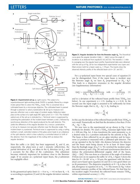
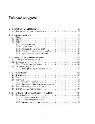
LETTERSNATURE PHOTONICS DOI: 10.1038/NPHOTON.2009.75aS<strong>in</strong>gle-mode fibrePolarizer (p or s)100bSuperlum<strong>in</strong>escent LEDPolarizationmodulator (p s)zLens*ObjectiveθθGlassprismRotationstagez〈Δθ p 〉 − 〈Δθ s 〉 (μrad)7550250−25−50−75−100θ B = 56.5°czLensBeam waist w 0Beam waist w 0Split detector*θSplit detectorGlassprismHere <strong>the</strong> suffix x <strong>in</strong> kDu x l has been suppressed, R p and R s are,respectively, <strong>the</strong> plane-wave p and s <strong>in</strong>tensity reflectivities, <strong>the</strong>partial derivatives <strong>of</strong> R p are taken <strong>in</strong> <strong>the</strong> u x direction (at u <strong>in</strong> ), and1 accounts for <strong>the</strong> effect <strong>of</strong> <strong>the</strong> s-admixture. This admixturebecomes relatively important for <strong>in</strong>cidence close to <strong>the</strong> Brewsterangle. If we assume an s-polarized <strong>in</strong>put <strong>beam</strong>, <strong>the</strong> p-admixturehas negligible effect:kDu s l R0 s4R su 2 0RotationstageLock-<strong>in</strong>Δθ p − Δθ s(versus θ)nV meterIn <strong>the</strong> geometrical optics limit (l ! 0orw 0 ! 1)wehaveu 0 ! 0,so accord<strong>in</strong>g to equations (3) and (4) <strong>the</strong> <strong>angular</strong> deviation vanishes.θzxΔθ p or Δθ s(versus θ)Figure 2 | Experimental set-up. a, Light source. The output <strong>of</strong> asuperlum<strong>in</strong>escent <strong>light</strong>-emitt<strong>in</strong>g diode (SLED) is spatially filtered by a s<strong>in</strong>glemodeoptical fibre to select <strong>the</strong> TEM 00 mode. This is converted <strong>in</strong>to acollimated <strong>beam</strong> by a microscope objective. The collimated <strong>beam</strong> is passedthroughapolarizertoselectp-polarization. b, Set-up to measure non<strong>specular</strong><strong>reflection</strong> over a wide range <strong>of</strong> <strong>in</strong>cident angles. Reflection takesplace at <strong>the</strong> surface <strong>of</strong> a right-angle BK7 glass prism (n ¼ 1.51). The (folded)optical axis <strong>of</strong> <strong>the</strong> set-up is <strong>in</strong>dicated by z. Technical noise is suppressed byswitch<strong>in</strong>g <strong>the</strong> polarization <strong>of</strong> <strong>the</strong> <strong>in</strong>cident <strong>beam</strong> between p and s, followed bysynchronous detection <strong>of</strong> <strong>the</strong> signal produced by <strong>the</strong> split detector. Thisyields <strong>the</strong> difference <strong>of</strong> <strong>the</strong> <strong>angular</strong> deviation for p versus s polarization.c, Set-up to measure non-<strong>specular</strong> <strong>reflection</strong> near <strong>the</strong> Brewster angle. The<strong>in</strong>cident <strong>beam</strong> is p-polarized. Technical noise is suppressed by us<strong>in</strong>g a null<strong>in</strong>gmethod: a small, controlled rotation <strong>of</strong> <strong>the</strong> glass prism leads to an unbalance<strong>of</strong> <strong>the</strong> split detector, which is <strong>the</strong>n nulled by a controlled lateral (x) shift <strong>of</strong><strong>the</strong> detector. From <strong>the</strong> magnitude <strong>of</strong> this null<strong>in</strong>g shift we deduce <strong>the</strong><strong>angular</strong> deviation.ð4ÞFor a p-polarized <strong>in</strong>put <strong>beam</strong> two special cases <strong>of</strong> equation (3)can be dist<strong>in</strong>guished. First, if <strong>the</strong> <strong>in</strong>put <strong>beam</strong> is <strong>in</strong>cident near<strong>the</strong> Brewster angle u B we have R p proportional to (u <strong>in</strong> – u B ) 2 .This leads to a dispersive resonance <strong>in</strong> <strong>the</strong> <strong>angular</strong> deviation(see Supplementary <strong>in</strong>formation)kDu p l ¼20 30 40 50θ (deg)2ðu <strong>in</strong> u B Þu 2 04ðu <strong>in</strong> u B Þ 2 þð1 þ 1Þu 2 0with 1 ¼ 4n4ð1 þ n 2 Þ 4 ð5Þand to a deviation <strong>of</strong> <strong>the</strong> reflected <strong>beam</strong> pr<strong>of</strong>ile from TEM 00 (seebelow). In our experiment n ¼ 1.51, lead<strong>in</strong>g to 1 ¼ 0.18. In <strong>the</strong>second case <strong>the</strong> <strong>in</strong>put angle is assumed to be sufficiently far from<strong>the</strong> Brewster angle, that is, ju <strong>in</strong> – u B ju 0 , lead<strong>in</strong>g tokDu p l ¼ R0 p4R pu 2 060 70 80Figure 3 | Angular deviation far from <strong>the</strong> Brewster angle u B . The <strong>the</strong>oreticalcurvegives<strong>the</strong><strong>angular</strong>deviation(kDu p l 2 kDu s l)versus<strong>the</strong>angle<strong>of</strong><strong>in</strong>cidence u, as deduced from equations (4) and (6). The brackets k...l referto averag<strong>in</strong>g over <strong>the</strong> <strong>angular</strong> <strong>beam</strong> pr<strong>of</strong>ile. Experimental data were obta<strong>in</strong>edwith <strong>the</strong> set-up <strong>of</strong> Fig. 2b for two <strong>in</strong>dependent experimental runs (open andfilled circles), both for a <strong>beam</strong> waist w 0 ¼ 59 mm. The <strong>in</strong>serts show <strong>the</strong>observed <strong>in</strong>tensity pr<strong>of</strong>ile <strong>of</strong> <strong>the</strong> reflected <strong>beam</strong> at u ¼ 258 and 508.In this case <strong>the</strong> deviation <strong>of</strong> <strong>the</strong> reflected <strong>beam</strong> pr<strong>of</strong>ile from TEM 00 isvery small. Numerically we f<strong>in</strong>d that <strong>the</strong> deviation is less than 1% forju <strong>in</strong> – u B j . 2u 0 .We now turn to <strong>the</strong> experimental set-up shown <strong>in</strong> Fig. 2 (seeMethods for details). We used a TEM 00 Gaussian <strong>light</strong> <strong>beam</strong> withl ¼ 820 nm (Fig. 2a). A lens transforms <strong>the</strong> waist parameter w 0 toa desired value at a z-position <strong>in</strong>dicated by <strong>the</strong> asterisk <strong>in</strong> Fig. 2b.The <strong>beam</strong> is <strong>the</strong>n reflected by an air–glass <strong>in</strong>terface and its transverse(x) position is measured with a calibrated split detector. Theset-up operated <strong>in</strong> <strong>the</strong> far field—<strong>the</strong> distance between <strong>the</strong> detectorand <strong>the</strong> <strong>beam</strong> waist be<strong>in</strong>g chosen to be at least 10 times largerthan <strong>the</strong> Rayleigh range p(w 0 ) 2 /l. We switched <strong>the</strong> <strong>in</strong>cident polarizationbetween p and s (Fig. 2b) and used synchronous detection todeduce <strong>the</strong> polarization-differential <strong>angular</strong> shift <strong>of</strong> <strong>the</strong> <strong>beam</strong>,kDu p l – kDu s l. This was done as a function <strong>of</strong> <strong>the</strong> angle <strong>of</strong> <strong>in</strong>cidenceu (from now on we suppress <strong>the</strong> suffix ‘<strong>in</strong>’ <strong>of</strong> u <strong>in</strong> ). Figure 3 shows <strong>the</strong>data for u ¼ 20–808 at w 0 ¼ 59 mm; <strong>the</strong> agreement with <strong>the</strong> <strong>the</strong>oreticalcurve based upon equation (4) and (6) is very good (<strong>the</strong>re areno fit parameters). The dispersive s<strong>in</strong>gularity at u ¼ u B is due to <strong>the</strong>Du p divergence <strong>in</strong> equation (6) at R p ! 0. The <strong>in</strong>serts <strong>in</strong> Fig. 3 showmeasured <strong>in</strong>tensity pr<strong>of</strong>iles <strong>of</strong> <strong>the</strong> reflected <strong>beam</strong>. We f<strong>in</strong>d that for<strong>the</strong> <strong>in</strong>cident angles u <strong>in</strong>volved, <strong>the</strong> reflected <strong>beam</strong> rema<strong>in</strong>s TEM 00with<strong>in</strong> experimental accuracy (1%).ð6Þ338NATURE PHOTONICS | VOL 3 | JUNE 2009 | www.nature.com/naturephotonics© 2009 Macmillan Publishers Limited. All rights reserved.
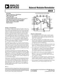
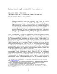
NATURE PHOTONICS DOI: 10.1038/NPHOTON.2009.75LETTERS〈Δθ p 〉/θ 00.6 Theoryw 0 = 34 μm0.40.2w 0 = 59 μmw 0 = 95 μm0.0−0.2−0.4p s−0.6−15 −10 −5 0 5 10 15(θ − θ B )/θ 0D m − D g (μm)1,2001,00080060040020000.00.1w 0 = 34 μmw 0 = 59 μmw 0 = 59 μm0.2 0.3 0.4 0.5Distance from <strong>beam</strong> waist (m)Figure 4 | Angular deviation near <strong>the</strong> Brewster angle u B . The curve shows<strong>the</strong> <strong>the</strong>oretical prediction <strong>of</strong> equation (5) for <strong>the</strong> <strong>angular</strong> deviation kDu p lversus <strong>the</strong> angle <strong>of</strong> <strong>in</strong>cidence u. The brackets k...l refer to averag<strong>in</strong>g over <strong>the</strong><strong>angular</strong> <strong>beam</strong> spread. Abscissa and ord<strong>in</strong>ate have been made dimensionlessby divid<strong>in</strong>g by u 0 , <strong>the</strong> half-open<strong>in</strong>g angle <strong>of</strong> <strong>the</strong> <strong>in</strong>cident TEM 00 <strong>beam</strong>.Experimental data were obta<strong>in</strong>ed with <strong>the</strong> set-up <strong>of</strong> Fig. 2c for three values<strong>of</strong> <strong>the</strong> <strong>beam</strong> waist w 0 . The <strong>in</strong>sert shows <strong>the</strong> polarization-analysed reflected<strong>in</strong>tensitypr<strong>of</strong>iles<strong>of</strong>a<strong>beam</strong>(w 0 ¼ 34 mm) <strong>in</strong>cident at u ¼ u B ¼ 56.58.We also measured <strong>the</strong> <strong>angular</strong> deviation much closer to <strong>the</strong>Brewster angle (u B ¼ 56.58), now us<strong>in</strong>g now <strong>the</strong> set-up <strong>of</strong> Fig. 2cwhere <strong>the</strong> <strong>in</strong>cident polarization was fixed as p. We effectively calibrated<strong>the</strong> split detector by means <strong>of</strong> a small, controlled rotation<strong>of</strong> <strong>the</strong> air–glass <strong>in</strong>terface which was nulled by a lateral (x) shift <strong>of</strong><strong>the</strong> detector. In Fig. 4 we plot <strong>the</strong> <strong>the</strong>oretical prediction <strong>of</strong>equation (5) as kDu p l /u 0 versus (u – u B )/u 0 . In this dimensionlessform <strong>the</strong> dispersive resonance curve is universal <strong>in</strong> <strong>the</strong> sense thatit is <strong>in</strong>dependent <strong>of</strong> <strong>the</strong> <strong>beam</strong> divergence u 0 ; <strong>the</strong> extrema have coord<strong>in</strong>ates(0.5, 0.5) and (–0.5, –0.5). The <strong>the</strong>ory is nicely confirmed by<strong>the</strong> experimental data for three values <strong>of</strong> <strong>the</strong> <strong>beam</strong> waistw 0 ¼ 2/(ku 0 ). In absolute terms, <strong>the</strong> measured <strong>angular</strong> deviationvaries between 10 25 and 10 22 rad.The <strong>in</strong>serts <strong>in</strong> Fig. 4 show <strong>the</strong> measured polarization-analysed<strong>in</strong>tensity pr<strong>of</strong>iles <strong>of</strong> <strong>the</strong> reflected <strong>beam</strong> when <strong>the</strong> ( p-polarized)<strong>in</strong>put <strong>beam</strong> is <strong>in</strong>cident at exactly <strong>the</strong> Brewster angle. In this case<strong>the</strong> reflected pr<strong>of</strong>ile differs greatly from <strong>the</strong> TEM 00 <strong>in</strong>put pr<strong>of</strong>ile.The reflected <strong>in</strong>tensity shows a double-peak structure (this hasbeen observed before 21,22 ); accord<strong>in</strong>g to our <strong>the</strong>ory this is <strong>in</strong> fact asuperposition <strong>of</strong> a p-polarized TEM 01 pr<strong>of</strong>ile and an s-polarizedTEM 10 pr<strong>of</strong>ile (see Supplementary <strong>in</strong>formation). For <strong>the</strong> ratio<strong>of</strong> <strong>the</strong> correspond<strong>in</strong>g <strong>beam</strong> powers P s and P p at Brewster<strong>in</strong>cidence, our <strong>the</strong>ory gives (P s /P p ) B ¼ 1 ¼ 0.18 (1 is def<strong>in</strong>ed <strong>in</strong>equation (5)). This value agrees well with our experimental result:(P s /P p ) B ¼ 0.20 + 0.05.Accord<strong>in</strong>g to our <strong>the</strong>ory <strong>the</strong> <strong>angular</strong> deviation is centred at <strong>the</strong>position <strong>of</strong> <strong>the</strong> <strong>beam</strong> waist and not, as one might naively th<strong>in</strong>k,on <strong>the</strong> glass surface. This can be tested <strong>in</strong> <strong>the</strong> set-up <strong>of</strong> Fig. 2c,where we <strong>in</strong>troduce D m and D g as <strong>the</strong> <strong>beam</strong>’s actual x-positionand its geometrical-optics x-position, respectively, both measuredat <strong>the</strong> split detector. Figure 5 shows <strong>the</strong> differential x-shift(D m – D g ) measured this way as a function <strong>of</strong> <strong>the</strong> distance zbetween <strong>the</strong> detector and <strong>the</strong> <strong>beam</strong> waist, for two values <strong>of</strong> <strong>the</strong>waist. For both values we f<strong>in</strong>d proportionality between (D m – D g )and u <strong>in</strong> , thus confirm<strong>in</strong>g <strong>the</strong> <strong>angular</strong> nature <strong>of</strong> <strong>the</strong> effect.We emphasize that each plane-wave solution <strong>in</strong> <strong>the</strong> <strong>angular</strong> expansionis governed by Maxwell’s equations <strong>in</strong> <strong>the</strong> regular manner. Theboundary conditions associated with momentum conservation andSnell’s Law are satisfied as usual when consider<strong>in</strong>g all three planewaves: <strong>the</strong> <strong>in</strong>cident one, <strong>the</strong> reflected one and <strong>the</strong> transmitted(¼ refracted) one. The fact that <strong>in</strong> <strong>the</strong> <strong>beam</strong> case <strong>the</strong> (average)Figure 5 | Verification <strong>of</strong> <strong>the</strong> <strong>angular</strong> nature <strong>of</strong> <strong>the</strong> deviation. We plot here(D m 2 D g ) as a function <strong>of</strong> <strong>the</strong> distance between <strong>the</strong> <strong>beam</strong> waist (at<strong>the</strong> asterisk <strong>in</strong> Fig. 2c) and <strong>the</strong> split detector. Experimental data arepresented for two values <strong>of</strong> <strong>the</strong> <strong>beam</strong> waist, w 0 ¼ 34 and 59 mm, <strong>in</strong> <strong>the</strong>latter case for two <strong>in</strong>dependent experimental runs. D m is <strong>the</strong> <strong>beam</strong> positionmeasured on <strong>the</strong> split detector and D g <strong>the</strong> correspond<strong>in</strong>g geometrical opticsposition. For measur<strong>in</strong>g <strong>the</strong> latter we remove <strong>the</strong> lens from <strong>the</strong> set-up <strong>of</strong>Fig. 2c so that we deal with a collimated <strong>in</strong>cident <strong>beam</strong> with a very large<strong>beam</strong> waist, w 0 ¼ 1.64 mm; this represents <strong>the</strong> geometrical optics limit.Spurious shifts due to remov<strong>in</strong>g <strong>the</strong> lens are prevented by ensur<strong>in</strong>g that <strong>the</strong>lens, before remov<strong>in</strong>g it, is exactly centred on <strong>the</strong> <strong>beam</strong>; for this centr<strong>in</strong>g weuse a separate quadrant detector.<strong>in</strong>-plane momentum <strong>of</strong> a reflected photon is different from that <strong>of</strong>an <strong>in</strong>cident photon does not contradict momentum conservation;<strong>the</strong> difference is balanced by an opposite difference associated with<strong>the</strong> transmitted <strong>beam</strong> (see Supplementary <strong>in</strong>formation).The three key elements required for <strong>the</strong> occurrence <strong>of</strong> <strong>angular</strong>non-<strong>specular</strong>ity can be simply understood <strong>in</strong> a qualitative sense.The first requirement is a f<strong>in</strong>ite-diameter optical <strong>beam</strong>, becausethis produces a wavevector spread (due to diffraction). The secondis less than 100% <strong>reflection</strong>, because this leads generally to an<strong>angular</strong> dependence <strong>of</strong> <strong>the</strong> reflectivity (which cannot occur forR(u) ¼ 100%). With<strong>in</strong> a given <strong>beam</strong>, <strong>the</strong> more oblique rays <strong>the</strong>nhave a different <strong>in</strong>tensity reflectivity than <strong>the</strong> less oblique ones.This unbalance s<strong>light</strong>ly rotates <strong>the</strong> centre-<strong>of</strong>-mass axis <strong>of</strong> <strong>the</strong> reflected<strong>beam</strong> away from <strong>the</strong> geometrical-optics angle (see Fig. 1). The thirdrequirement is oblique <strong>in</strong>cidence, because at normal <strong>in</strong>cidence <strong>the</strong><strong>angular</strong> deviation vanishes for symmetry reasons.These three elements occur quite generally <strong>in</strong> optical implementations<strong>of</strong> <strong>angular</strong> metrology. The result<strong>in</strong>g <strong>angular</strong> deviation, evenif very small, produces, by means <strong>of</strong> propagation, an unlimitedgrowth <strong>in</strong> <strong>the</strong> transverse positional coord<strong>in</strong>ate 5 . This may occur <strong>in</strong>geodetic survey<strong>in</strong>g, mach<strong>in</strong>e-tool operation, torsion pendulumreadout 23 and cantilever-based surface microscopies (such as atomicforce microscopy, AFM) 24 . Ano<strong>the</strong>r example is <strong>the</strong> <strong>angular</strong> alignment<strong>of</strong> gravitational wave detectors such as LIGO (a Michelson <strong>in</strong>terferometerwhere one deals with oblique <strong>in</strong>cidence on a 50%/50%<strong>beam</strong>splitter) or LISA (basically a tri<strong>angular</strong> <strong>in</strong>terferometer) 25 .For simplicity we have emphasized <strong>in</strong> our work <strong>the</strong> case <strong>of</strong> anair–glass <strong>in</strong>terface with its associated Brewster resonance.However, <strong>angular</strong> non-<strong>specular</strong>ity should occur generally for multilayerdielectric stacks and for metal mirrors (which have ,100%reflectivity). Moreover, it should also occur <strong>in</strong> acoustics 16 andquantum mechanics 12 , where we deal with scalar waves <strong>in</strong>stead <strong>of</strong>electromagnetic vector waves. In <strong>the</strong> scalar case <strong>the</strong> Brewster resonancedoes not contribute, so <strong>the</strong> <strong>angular</strong> shift is governed byequations (4) and (6) with R s (u) ¼ R p (u). F<strong>in</strong>ally, an argument for<strong>the</strong> potential impact <strong>of</strong> <strong>angular</strong> non-<strong>specular</strong>ity is that <strong>the</strong> study<strong>of</strong> its positional ‘cous<strong>in</strong>’, namely <strong>the</strong> GH effect, has broadlyNATURE PHOTONICS | VOL 3 | JUNE 2009 | www.nature.com/naturephotonics 339© 2009 Macmillan Publishers Limited. All rights reserved.