Observing angular deviations in the specular reflection of a light beam
Observing angular deviations in the specular reflection of a light beam
Observing angular deviations in the specular reflection of a light beam

Create successful ePaper yourself
Turn your PDF publications into a flip-book with our unique Google optimized e-Paper software.
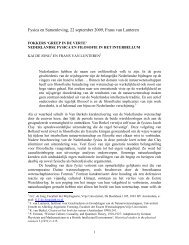
LETTERSPUBLISHED ONLINE: 17 MAY 2009 | DOI: 10.1038/NPHOTON.2009.75<strong>Observ<strong>in</strong>g</strong> <strong>angular</strong> <strong>deviations</strong> <strong>in</strong> <strong>the</strong> <strong>specular</strong><strong>reflection</strong> <strong>of</strong> a <strong>light</strong> <strong>beam</strong>M. Merano, A. Aiello † ,M.P.vanExterandJ.P.Woerdman*The Law <strong>of</strong> Reflection <strong>of</strong> a <strong>light</strong> ray <strong>in</strong>cident upon a mirror(u <strong>in</strong> 5 u out ) was first formulated by Euclid around 300 BC <strong>in</strong>his book Catoptrics 1 ; it has been a tenet <strong>of</strong> geometrical opticsever s<strong>in</strong>ce. However, more recently, a small <strong>angular</strong> deviation<strong>of</strong> <strong>the</strong> Law <strong>of</strong> Reflection has been predicted for a physical<strong>light</strong> <strong>beam</strong> when this is regarded as <strong>the</strong> implementation <strong>of</strong> aray 2–5 . The deviation is a diffractive consequence <strong>of</strong> <strong>the</strong><strong>angular</strong> dependence <strong>of</strong> <strong>the</strong> reflectivity and should occur forany mirror with less than 100% reflectivity. We report hereexperimental pro<strong>of</strong> <strong>of</strong> this <strong>angular</strong> deviation by determ<strong>in</strong><strong>in</strong>g<strong>the</strong> direction <strong>of</strong> an optical <strong>beam</strong> after <strong>reflection</strong> from an air–glass <strong>in</strong>terface, us<strong>in</strong>g a position detector with nanometre resolution.Our results are relevant for <strong>angular</strong> metrology <strong>in</strong> generaland cantilever-based surface microscopies <strong>in</strong> particular.Analogous <strong>angular</strong> <strong>deviations</strong> are expected for <strong>reflection</strong> <strong>of</strong>acoustic waves and quantum matter waves.The <strong>reflection</strong> <strong>of</strong> a <strong>light</strong> <strong>beam</strong> by a planar dielectric <strong>in</strong>terface has<strong>in</strong>trigu<strong>in</strong>g characteristics that have long been <strong>the</strong> subject <strong>of</strong> study 6,7 .Interest has ma<strong>in</strong>ly focused on <strong>the</strong> Goos–Hänchen (GH) shift,which is a positional shift <strong>of</strong> <strong>the</strong> <strong>beam</strong> centre relative to its geometricaloptics position 6 . The GH shift is proportional to <strong>the</strong> <strong>angular</strong>derivative <strong>of</strong> <strong>the</strong> phase <strong>of</strong> <strong>the</strong> complex reflectivity r, and occurs <strong>in</strong>particular under conditions <strong>of</strong> total <strong>in</strong>ternal <strong>reflection</strong> (TIR),where this derivative can become large 7 . The GH shift has beenstudied <strong>in</strong> photonic crystals, plasmonics, near-field optics, nonl<strong>in</strong>earoptics, negative-<strong>in</strong>dex media, acoustics and atom optics 8–17 .There is a relatively unknown related effect, namely an <strong>angular</strong>deviation <strong>of</strong> <strong>the</strong> <strong>beam</strong> axis that occurs only <strong>in</strong> <strong>the</strong> case <strong>of</strong> partial,that is, non-total <strong>reflection</strong> 2–4,18,19 . This <strong>angular</strong> shift is proportionalto <strong>the</strong> <strong>angular</strong> derivative <strong>of</strong> <strong>the</strong> amplitude reflectivity jrj. Currentlyavailable <strong>the</strong>ory 2–4 is deficient <strong>in</strong> describ<strong>in</strong>g this because it addressesa two-dimensional geometry with sheet-shaped <strong>light</strong> <strong>beam</strong>s; as weshow here, a full three-dimensional treatment is essential for <strong>in</strong>cidencenear <strong>the</strong> Brewster angle. Experimentally, <strong>angular</strong> deviationhas been studied <strong>in</strong> <strong>the</strong> microwave doma<strong>in</strong> 19 . We report here <strong>the</strong>first experimental observation <strong>of</strong> <strong>angular</strong> deviation <strong>in</strong> <strong>the</strong> opticaldoma<strong>in</strong> and compare this with <strong>the</strong>ory that takes <strong>in</strong>to account <strong>the</strong>three-dimensional nature <strong>of</strong> <strong>the</strong> <strong>beam</strong>. The optical doma<strong>in</strong> isparticularly relevant <strong>in</strong> view <strong>of</strong> <strong>the</strong> importance <strong>of</strong> optical methodology<strong>in</strong> science and eng<strong>in</strong>eer<strong>in</strong>g.Theoretically, we calculated <strong>the</strong> magnitude <strong>of</strong> <strong>the</strong> <strong>angular</strong> shiftus<strong>in</strong>g <strong>the</strong> <strong>in</strong>tensities and not <strong>the</strong> amplitudes <strong>of</strong> <strong>the</strong> plane wavesthat constitute <strong>the</strong> <strong>beam</strong>. This simplification is valid because onlyone plane wave contributes to <strong>the</strong> far field at a given angle, <strong>the</strong>effect <strong>of</strong> <strong>the</strong> o<strong>the</strong>r plane waves be<strong>in</strong>g cancelled by destructive <strong>in</strong>terference20 (our experiments are <strong>in</strong>deed <strong>in</strong> <strong>the</strong> far field, as is apparent<strong>in</strong> <strong>the</strong> follow<strong>in</strong>g). For <strong>the</strong> positional (GH) shift that occurs <strong>in</strong> <strong>the</strong>near field, such an <strong>in</strong>tensity-based treatment would be wrong. Wehave also constructed a general, amplitude-based <strong>the</strong>ory, show<strong>in</strong>gGlassthat <strong>the</strong> <strong>angular</strong> and positional shifts are, respectively, <strong>the</strong> imag<strong>in</strong>aryand real parts <strong>of</strong> a complex-valued analytical function 5,18 . This<strong>the</strong>ory reduces <strong>in</strong> <strong>the</strong> far field to <strong>the</strong> more <strong>in</strong>tuitively based <strong>in</strong>tensityapproach that we present here.We <strong>in</strong>troduce <strong>in</strong> Fig. 1 a TEM 00 <strong>beam</strong> <strong>of</strong> wavelength l, waist parameterw 0 and <strong>angular</strong> half-width u 0 ; <strong>the</strong>se parameters are related by<strong>the</strong> relation u 0 ¼ 2/(kw 0 ), where k ¼ 2p/l (ref. 20). We decompose<strong>the</strong> <strong>in</strong>tensity <strong>of</strong> this <strong>beam</strong> <strong>in</strong>to plane waves (‘rays’) travell<strong>in</strong>g atangles u x and u y relative to <strong>the</strong> <strong>beam</strong> axis h iI u x ; u y / exp 2 u 2 x þ u 2 y =u 2 0ð1ÞIntroduc<strong>in</strong>g R(u x , u y ) as <strong>the</strong> <strong>in</strong>tensity <strong>reflection</strong> coefficient <strong>of</strong> <strong>the</strong> planewave (u x , u y ), we denote <strong>the</strong> reflected <strong>beam</strong> as R(u x , u y )I(u x , u y ).We def<strong>in</strong>e <strong>the</strong> (‘centre-<strong>of</strong>-mass’) <strong>angular</strong> deviation <strong>of</strong> <strong>the</strong> reflected<strong>beam</strong>, <strong>in</strong> <strong>the</strong> plane <strong>of</strong> <strong>in</strong>cidence as kDu x l ¼ÐÐux R u x ; u yÐÐ R ux ; u y I u x ; u yI u x ; u y du x du y ð2Þdu x du yThe <strong>in</strong>put <strong>beam</strong> is assumed to be l<strong>in</strong>early polarized, ei<strong>the</strong>r s or p(respectively perpendicular or parallel to <strong>the</strong> plane <strong>of</strong> <strong>in</strong>cidence).We first assume p-polarization. The f<strong>in</strong>ite divergence <strong>of</strong> <strong>the</strong> <strong>beam</strong>unavoidably implies a small admixture <strong>of</strong> s-polarization; this leadsto <strong>the</strong> expression (see Supplementary <strong>in</strong>formation) R 0 pu 2 2 R0s R pkDu p l xy2θ 0Airθ <strong>in</strong>Figure 1 | Schematic representation <strong>of</strong> non-<strong>specular</strong> <strong>angular</strong> <strong>reflection</strong>.ATEM 00 Gaussian <strong>beam</strong> hits an air–glass <strong>in</strong>terface; <strong>the</strong> <strong>beam</strong> is modelled asa bundle <strong>of</strong> rays with a full open<strong>in</strong>g angle 2u 0 and with u <strong>in</strong> as <strong>the</strong> centralangle <strong>of</strong> <strong>in</strong>cidence. Transverse <strong>beam</strong> coord<strong>in</strong>ates are <strong>in</strong>dicated as (x, y),where x is <strong>in</strong> <strong>the</strong> plane <strong>of</strong> <strong>in</strong>cidence and y perpendicular to it. The reflectivity<strong>of</strong> a given ray depends on its angle <strong>of</strong> <strong>in</strong>cidence; <strong>the</strong> length <strong>of</strong> a ray arrowsymbolizes <strong>the</strong> ray <strong>in</strong>tensity before and after <strong>reflection</strong>. The <strong>angular</strong>deviation <strong>of</strong> <strong>the</strong> axis <strong>of</strong> <strong>the</strong> reflected <strong>beam</strong> relative to <strong>the</strong> <strong>specular</strong> directionis labelled as Du.θ <strong>in</strong>4R p þð1=2ÞR 00 pð1 þ 1Þu 2 0xywith 1 ;ΔθR 00 p tan2 u <strong>in</strong>ð3ÞHuygens Laboratory, Leiden University, PO Box 9504, 2300RA Leiden, The Ne<strong>the</strong>rlands; † Present address: Max Planck Institute for <strong>the</strong> Science <strong>of</strong> Light,Gün<strong>the</strong>r-Scharowsky-Strasse 1/Bau 24, 91058 Erlangen, Germany. *e-mail: woerdman@molphys.leidenuniv.nlNATURE PHOTONICS | VOL 3 | JUNE 2009 | www.nature.com/naturephotonics 337© 2009 Macmillan Publishers Limited. All rights reserved.
LETTERSNATURE PHOTONICS DOI: 10.1038/NPHOTON.2009.75aS<strong>in</strong>gle-mode fibrePolarizer (p or s)100bSuperlum<strong>in</strong>escent LEDPolarizationmodulator (p s)zLens*ObjectiveθθGlassprismRotationstagez〈Δθ p 〉 − 〈Δθ s 〉 (μrad)7550250−25−50−75−100θ B = 56.5°czLensBeam waist w 0Beam waist w 0Split detector*θSplit detectorGlassprismHere <strong>the</strong> suffix x <strong>in</strong> kDu x l has been suppressed, R p and R s are,respectively, <strong>the</strong> plane-wave p and s <strong>in</strong>tensity reflectivities, <strong>the</strong>partial derivatives <strong>of</strong> R p are taken <strong>in</strong> <strong>the</strong> u x direction (at u <strong>in</strong> ), and1 accounts for <strong>the</strong> effect <strong>of</strong> <strong>the</strong> s-admixture. This admixturebecomes relatively important for <strong>in</strong>cidence close to <strong>the</strong> Brewsterangle. If we assume an s-polarized <strong>in</strong>put <strong>beam</strong>, <strong>the</strong> p-admixturehas negligible effect:kDu s l R0 s4R su 2 0RotationstageLock-<strong>in</strong>Δθ p − Δθ s(versus θ)nV meterIn <strong>the</strong> geometrical optics limit (l ! 0orw 0 ! 1)wehaveu 0 ! 0,so accord<strong>in</strong>g to equations (3) and (4) <strong>the</strong> <strong>angular</strong> deviation vanishes.θzxΔθ p or Δθ s(versus θ)Figure 2 | Experimental set-up. a, Light source. The output <strong>of</strong> asuperlum<strong>in</strong>escent <strong>light</strong>-emitt<strong>in</strong>g diode (SLED) is spatially filtered by a s<strong>in</strong>glemodeoptical fibre to select <strong>the</strong> TEM 00 mode. This is converted <strong>in</strong>to acollimated <strong>beam</strong> by a microscope objective. The collimated <strong>beam</strong> is passedthroughapolarizertoselectp-polarization. b, Set-up to measure non<strong>specular</strong><strong>reflection</strong> over a wide range <strong>of</strong> <strong>in</strong>cident angles. Reflection takesplace at <strong>the</strong> surface <strong>of</strong> a right-angle BK7 glass prism (n ¼ 1.51). The (folded)optical axis <strong>of</strong> <strong>the</strong> set-up is <strong>in</strong>dicated by z. Technical noise is suppressed byswitch<strong>in</strong>g <strong>the</strong> polarization <strong>of</strong> <strong>the</strong> <strong>in</strong>cident <strong>beam</strong> between p and s, followed bysynchronous detection <strong>of</strong> <strong>the</strong> signal produced by <strong>the</strong> split detector. Thisyields <strong>the</strong> difference <strong>of</strong> <strong>the</strong> <strong>angular</strong> deviation for p versus s polarization.c, Set-up to measure non-<strong>specular</strong> <strong>reflection</strong> near <strong>the</strong> Brewster angle. The<strong>in</strong>cident <strong>beam</strong> is p-polarized. Technical noise is suppressed by us<strong>in</strong>g a null<strong>in</strong>gmethod: a small, controlled rotation <strong>of</strong> <strong>the</strong> glass prism leads to an unbalance<strong>of</strong> <strong>the</strong> split detector, which is <strong>the</strong>n nulled by a controlled lateral (x) shift <strong>of</strong><strong>the</strong> detector. From <strong>the</strong> magnitude <strong>of</strong> this null<strong>in</strong>g shift we deduce <strong>the</strong><strong>angular</strong> deviation.ð4ÞFor a p-polarized <strong>in</strong>put <strong>beam</strong> two special cases <strong>of</strong> equation (3)can be dist<strong>in</strong>guished. First, if <strong>the</strong> <strong>in</strong>put <strong>beam</strong> is <strong>in</strong>cident near<strong>the</strong> Brewster angle u B we have R p proportional to (u <strong>in</strong> – u B ) 2 .This leads to a dispersive resonance <strong>in</strong> <strong>the</strong> <strong>angular</strong> deviation(see Supplementary <strong>in</strong>formation)kDu p l ¼20 30 40 50θ (deg)2ðu <strong>in</strong> u B Þu 2 04ðu <strong>in</strong> u B Þ 2 þð1 þ 1Þu 2 0with 1 ¼ 4n4ð1 þ n 2 Þ 4 ð5Þand to a deviation <strong>of</strong> <strong>the</strong> reflected <strong>beam</strong> pr<strong>of</strong>ile from TEM 00 (seebelow). In our experiment n ¼ 1.51, lead<strong>in</strong>g to 1 ¼ 0.18. In <strong>the</strong>second case <strong>the</strong> <strong>in</strong>put angle is assumed to be sufficiently far from<strong>the</strong> Brewster angle, that is, ju <strong>in</strong> – u B ju 0 , lead<strong>in</strong>g tokDu p l ¼ R0 p4R pu 2 060 70 80Figure 3 | Angular deviation far from <strong>the</strong> Brewster angle u B . The <strong>the</strong>oreticalcurvegives<strong>the</strong><strong>angular</strong>deviation(kDu p l 2 kDu s l)versus<strong>the</strong>angle<strong>of</strong><strong>in</strong>cidence u, as deduced from equations (4) and (6). The brackets k...l referto averag<strong>in</strong>g over <strong>the</strong> <strong>angular</strong> <strong>beam</strong> pr<strong>of</strong>ile. Experimental data were obta<strong>in</strong>edwith <strong>the</strong> set-up <strong>of</strong> Fig. 2b for two <strong>in</strong>dependent experimental runs (open andfilled circles), both for a <strong>beam</strong> waist w 0 ¼ 59 mm. The <strong>in</strong>serts show <strong>the</strong>observed <strong>in</strong>tensity pr<strong>of</strong>ile <strong>of</strong> <strong>the</strong> reflected <strong>beam</strong> at u ¼ 258 and 508.In this case <strong>the</strong> deviation <strong>of</strong> <strong>the</strong> reflected <strong>beam</strong> pr<strong>of</strong>ile from TEM 00 isvery small. Numerically we f<strong>in</strong>d that <strong>the</strong> deviation is less than 1% forju <strong>in</strong> – u B j . 2u 0 .We now turn to <strong>the</strong> experimental set-up shown <strong>in</strong> Fig. 2 (seeMethods for details). We used a TEM 00 Gaussian <strong>light</strong> <strong>beam</strong> withl ¼ 820 nm (Fig. 2a). A lens transforms <strong>the</strong> waist parameter w 0 toa desired value at a z-position <strong>in</strong>dicated by <strong>the</strong> asterisk <strong>in</strong> Fig. 2b.The <strong>beam</strong> is <strong>the</strong>n reflected by an air–glass <strong>in</strong>terface and its transverse(x) position is measured with a calibrated split detector. Theset-up operated <strong>in</strong> <strong>the</strong> far field—<strong>the</strong> distance between <strong>the</strong> detectorand <strong>the</strong> <strong>beam</strong> waist be<strong>in</strong>g chosen to be at least 10 times largerthan <strong>the</strong> Rayleigh range p(w 0 ) 2 /l. We switched <strong>the</strong> <strong>in</strong>cident polarizationbetween p and s (Fig. 2b) and used synchronous detection todeduce <strong>the</strong> polarization-differential <strong>angular</strong> shift <strong>of</strong> <strong>the</strong> <strong>beam</strong>,kDu p l – kDu s l. This was done as a function <strong>of</strong> <strong>the</strong> angle <strong>of</strong> <strong>in</strong>cidenceu (from now on we suppress <strong>the</strong> suffix ‘<strong>in</strong>’ <strong>of</strong> u <strong>in</strong> ). Figure 3 shows <strong>the</strong>data for u ¼ 20–808 at w 0 ¼ 59 mm; <strong>the</strong> agreement with <strong>the</strong> <strong>the</strong>oreticalcurve based upon equation (4) and (6) is very good (<strong>the</strong>re areno fit parameters). The dispersive s<strong>in</strong>gularity at u ¼ u B is due to <strong>the</strong>Du p divergence <strong>in</strong> equation (6) at R p ! 0. The <strong>in</strong>serts <strong>in</strong> Fig. 3 showmeasured <strong>in</strong>tensity pr<strong>of</strong>iles <strong>of</strong> <strong>the</strong> reflected <strong>beam</strong>. We f<strong>in</strong>d that for<strong>the</strong> <strong>in</strong>cident angles u <strong>in</strong>volved, <strong>the</strong> reflected <strong>beam</strong> rema<strong>in</strong>s TEM 00with<strong>in</strong> experimental accuracy (1%).ð6Þ338NATURE PHOTONICS | VOL 3 | JUNE 2009 | www.nature.com/naturephotonics© 2009 Macmillan Publishers Limited. All rights reserved.
NATURE PHOTONICS DOI: 10.1038/NPHOTON.2009.75LETTERS〈Δθ p 〉/θ 00.6 Theoryw 0 = 34 μm0.40.2w 0 = 59 μmw 0 = 95 μm0.0−0.2−0.4p s−0.6−15 −10 −5 0 5 10 15(θ − θ B )/θ 0D m − D g (μm)1,2001,00080060040020000.00.1w 0 = 34 μmw 0 = 59 μmw 0 = 59 μm0.2 0.3 0.4 0.5Distance from <strong>beam</strong> waist (m)Figure 4 | Angular deviation near <strong>the</strong> Brewster angle u B . The curve shows<strong>the</strong> <strong>the</strong>oretical prediction <strong>of</strong> equation (5) for <strong>the</strong> <strong>angular</strong> deviation kDu p lversus <strong>the</strong> angle <strong>of</strong> <strong>in</strong>cidence u. The brackets k...l refer to averag<strong>in</strong>g over <strong>the</strong><strong>angular</strong> <strong>beam</strong> spread. Abscissa and ord<strong>in</strong>ate have been made dimensionlessby divid<strong>in</strong>g by u 0 , <strong>the</strong> half-open<strong>in</strong>g angle <strong>of</strong> <strong>the</strong> <strong>in</strong>cident TEM 00 <strong>beam</strong>.Experimental data were obta<strong>in</strong>ed with <strong>the</strong> set-up <strong>of</strong> Fig. 2c for three values<strong>of</strong> <strong>the</strong> <strong>beam</strong> waist w 0 . The <strong>in</strong>sert shows <strong>the</strong> polarization-analysed reflected<strong>in</strong>tensitypr<strong>of</strong>iles<strong>of</strong>a<strong>beam</strong>(w 0 ¼ 34 mm) <strong>in</strong>cident at u ¼ u B ¼ 56.58.We also measured <strong>the</strong> <strong>angular</strong> deviation much closer to <strong>the</strong>Brewster angle (u B ¼ 56.58), now us<strong>in</strong>g now <strong>the</strong> set-up <strong>of</strong> Fig. 2cwhere <strong>the</strong> <strong>in</strong>cident polarization was fixed as p. We effectively calibrated<strong>the</strong> split detector by means <strong>of</strong> a small, controlled rotation<strong>of</strong> <strong>the</strong> air–glass <strong>in</strong>terface which was nulled by a lateral (x) shift <strong>of</strong><strong>the</strong> detector. In Fig. 4 we plot <strong>the</strong> <strong>the</strong>oretical prediction <strong>of</strong>equation (5) as kDu p l /u 0 versus (u – u B )/u 0 . In this dimensionlessform <strong>the</strong> dispersive resonance curve is universal <strong>in</strong> <strong>the</strong> sense thatit is <strong>in</strong>dependent <strong>of</strong> <strong>the</strong> <strong>beam</strong> divergence u 0 ; <strong>the</strong> extrema have coord<strong>in</strong>ates(0.5, 0.5) and (–0.5, –0.5). The <strong>the</strong>ory is nicely confirmed by<strong>the</strong> experimental data for three values <strong>of</strong> <strong>the</strong> <strong>beam</strong> waistw 0 ¼ 2/(ku 0 ). In absolute terms, <strong>the</strong> measured <strong>angular</strong> deviationvaries between 10 25 and 10 22 rad.The <strong>in</strong>serts <strong>in</strong> Fig. 4 show <strong>the</strong> measured polarization-analysed<strong>in</strong>tensity pr<strong>of</strong>iles <strong>of</strong> <strong>the</strong> reflected <strong>beam</strong> when <strong>the</strong> ( p-polarized)<strong>in</strong>put <strong>beam</strong> is <strong>in</strong>cident at exactly <strong>the</strong> Brewster angle. In this case<strong>the</strong> reflected pr<strong>of</strong>ile differs greatly from <strong>the</strong> TEM 00 <strong>in</strong>put pr<strong>of</strong>ile.The reflected <strong>in</strong>tensity shows a double-peak structure (this hasbeen observed before 21,22 ); accord<strong>in</strong>g to our <strong>the</strong>ory this is <strong>in</strong> fact asuperposition <strong>of</strong> a p-polarized TEM 01 pr<strong>of</strong>ile and an s-polarizedTEM 10 pr<strong>of</strong>ile (see Supplementary <strong>in</strong>formation). For <strong>the</strong> ratio<strong>of</strong> <strong>the</strong> correspond<strong>in</strong>g <strong>beam</strong> powers P s and P p at Brewster<strong>in</strong>cidence, our <strong>the</strong>ory gives (P s /P p ) B ¼ 1 ¼ 0.18 (1 is def<strong>in</strong>ed <strong>in</strong>equation (5)). This value agrees well with our experimental result:(P s /P p ) B ¼ 0.20 + 0.05.Accord<strong>in</strong>g to our <strong>the</strong>ory <strong>the</strong> <strong>angular</strong> deviation is centred at <strong>the</strong>position <strong>of</strong> <strong>the</strong> <strong>beam</strong> waist and not, as one might naively th<strong>in</strong>k,on <strong>the</strong> glass surface. This can be tested <strong>in</strong> <strong>the</strong> set-up <strong>of</strong> Fig. 2c,where we <strong>in</strong>troduce D m and D g as <strong>the</strong> <strong>beam</strong>’s actual x-positionand its geometrical-optics x-position, respectively, both measuredat <strong>the</strong> split detector. Figure 5 shows <strong>the</strong> differential x-shift(D m – D g ) measured this way as a function <strong>of</strong> <strong>the</strong> distance zbetween <strong>the</strong> detector and <strong>the</strong> <strong>beam</strong> waist, for two values <strong>of</strong> <strong>the</strong>waist. For both values we f<strong>in</strong>d proportionality between (D m – D g )and u <strong>in</strong> , thus confirm<strong>in</strong>g <strong>the</strong> <strong>angular</strong> nature <strong>of</strong> <strong>the</strong> effect.We emphasize that each plane-wave solution <strong>in</strong> <strong>the</strong> <strong>angular</strong> expansionis governed by Maxwell’s equations <strong>in</strong> <strong>the</strong> regular manner. Theboundary conditions associated with momentum conservation andSnell’s Law are satisfied as usual when consider<strong>in</strong>g all three planewaves: <strong>the</strong> <strong>in</strong>cident one, <strong>the</strong> reflected one and <strong>the</strong> transmitted(¼ refracted) one. The fact that <strong>in</strong> <strong>the</strong> <strong>beam</strong> case <strong>the</strong> (average)Figure 5 | Verification <strong>of</strong> <strong>the</strong> <strong>angular</strong> nature <strong>of</strong> <strong>the</strong> deviation. We plot here(D m 2 D g ) as a function <strong>of</strong> <strong>the</strong> distance between <strong>the</strong> <strong>beam</strong> waist (at<strong>the</strong> asterisk <strong>in</strong> Fig. 2c) and <strong>the</strong> split detector. Experimental data arepresented for two values <strong>of</strong> <strong>the</strong> <strong>beam</strong> waist, w 0 ¼ 34 and 59 mm, <strong>in</strong> <strong>the</strong>latter case for two <strong>in</strong>dependent experimental runs. D m is <strong>the</strong> <strong>beam</strong> positionmeasured on <strong>the</strong> split detector and D g <strong>the</strong> correspond<strong>in</strong>g geometrical opticsposition. For measur<strong>in</strong>g <strong>the</strong> latter we remove <strong>the</strong> lens from <strong>the</strong> set-up <strong>of</strong>Fig. 2c so that we deal with a collimated <strong>in</strong>cident <strong>beam</strong> with a very large<strong>beam</strong> waist, w 0 ¼ 1.64 mm; this represents <strong>the</strong> geometrical optics limit.Spurious shifts due to remov<strong>in</strong>g <strong>the</strong> lens are prevented by ensur<strong>in</strong>g that <strong>the</strong>lens, before remov<strong>in</strong>g it, is exactly centred on <strong>the</strong> <strong>beam</strong>; for this centr<strong>in</strong>g weuse a separate quadrant detector.<strong>in</strong>-plane momentum <strong>of</strong> a reflected photon is different from that <strong>of</strong>an <strong>in</strong>cident photon does not contradict momentum conservation;<strong>the</strong> difference is balanced by an opposite difference associated with<strong>the</strong> transmitted <strong>beam</strong> (see Supplementary <strong>in</strong>formation).The three key elements required for <strong>the</strong> occurrence <strong>of</strong> <strong>angular</strong>non-<strong>specular</strong>ity can be simply understood <strong>in</strong> a qualitative sense.The first requirement is a f<strong>in</strong>ite-diameter optical <strong>beam</strong>, becausethis produces a wavevector spread (due to diffraction). The secondis less than 100% <strong>reflection</strong>, because this leads generally to an<strong>angular</strong> dependence <strong>of</strong> <strong>the</strong> reflectivity (which cannot occur forR(u) ¼ 100%). With<strong>in</strong> a given <strong>beam</strong>, <strong>the</strong> more oblique rays <strong>the</strong>nhave a different <strong>in</strong>tensity reflectivity than <strong>the</strong> less oblique ones.This unbalance s<strong>light</strong>ly rotates <strong>the</strong> centre-<strong>of</strong>-mass axis <strong>of</strong> <strong>the</strong> reflected<strong>beam</strong> away from <strong>the</strong> geometrical-optics angle (see Fig. 1). The thirdrequirement is oblique <strong>in</strong>cidence, because at normal <strong>in</strong>cidence <strong>the</strong><strong>angular</strong> deviation vanishes for symmetry reasons.These three elements occur quite generally <strong>in</strong> optical implementations<strong>of</strong> <strong>angular</strong> metrology. The result<strong>in</strong>g <strong>angular</strong> deviation, evenif very small, produces, by means <strong>of</strong> propagation, an unlimitedgrowth <strong>in</strong> <strong>the</strong> transverse positional coord<strong>in</strong>ate 5 . This may occur <strong>in</strong>geodetic survey<strong>in</strong>g, mach<strong>in</strong>e-tool operation, torsion pendulumreadout 23 and cantilever-based surface microscopies (such as atomicforce microscopy, AFM) 24 . Ano<strong>the</strong>r example is <strong>the</strong> <strong>angular</strong> alignment<strong>of</strong> gravitational wave detectors such as LIGO (a Michelson <strong>in</strong>terferometerwhere one deals with oblique <strong>in</strong>cidence on a 50%/50%<strong>beam</strong>splitter) or LISA (basically a tri<strong>angular</strong> <strong>in</strong>terferometer) 25 .For simplicity we have emphasized <strong>in</strong> our work <strong>the</strong> case <strong>of</strong> anair–glass <strong>in</strong>terface with its associated Brewster resonance.However, <strong>angular</strong> non-<strong>specular</strong>ity should occur generally for multilayerdielectric stacks and for metal mirrors (which have ,100%reflectivity). Moreover, it should also occur <strong>in</strong> acoustics 16 andquantum mechanics 12 , where we deal with scalar waves <strong>in</strong>stead <strong>of</strong>electromagnetic vector waves. In <strong>the</strong> scalar case <strong>the</strong> Brewster resonancedoes not contribute, so <strong>the</strong> <strong>angular</strong> shift is governed byequations (4) and (6) with R s (u) ¼ R p (u). F<strong>in</strong>ally, an argument for<strong>the</strong> potential impact <strong>of</strong> <strong>angular</strong> non-<strong>specular</strong>ity is that <strong>the</strong> study<strong>of</strong> its positional ‘cous<strong>in</strong>’, namely <strong>the</strong> GH effect, has broadlyNATURE PHOTONICS | VOL 3 | JUNE 2009 | www.nature.com/naturephotonics 339© 2009 Macmillan Publishers Limited. All rights reserved.
LETTERSramified 8–17 (over 300 papers <strong>in</strong> 1947–2008). It would also be<strong>in</strong>terest<strong>in</strong>g to explore (some <strong>of</strong>) <strong>the</strong>se issues for <strong>the</strong> <strong>angular</strong> case.MethodsOur <strong>light</strong> source was a temperature-controlled fibre-pigtailed superlum<strong>in</strong>escent<strong>light</strong>-emitt<strong>in</strong>g diode (SLED) with P ¼ 2mW,l ¼ 820 nm and Dl ¼ 25 nm(InPhenix IPSDD0802). Its large spectral width (compared to a diode laser) helpedto elim<strong>in</strong>ate coherent speckle formation <strong>in</strong> <strong>the</strong> rest <strong>of</strong> <strong>the</strong> optical tra<strong>in</strong>; such specklecan easily compromise <strong>the</strong> high-precision position measurements <strong>of</strong> a <strong>beam</strong>.Ano<strong>the</strong>r advantage <strong>of</strong> a SLED when compared to a diode laser is <strong>the</strong> absence <strong>of</strong>higher-order transverse modes; this leads to superior <strong>beam</strong> po<strong>in</strong>t<strong>in</strong>g stability (nomode competition). The output <strong>of</strong> <strong>the</strong> SLED was sent through a s<strong>in</strong>gle-mode opticalfibre that acted as a spatial filter; <strong>the</strong> output facet <strong>of</strong> <strong>the</strong> fibre was positioned at <strong>the</strong>focus <strong>of</strong> a microscope objective (10). This objective produced a collimated (TEM 00 )<strong>light</strong> <strong>beam</strong> with a Gaussian waist parameter w 0 ¼ 1.64 mm. This was passed through apolarizer to select p-polarization, result<strong>in</strong>g <strong>in</strong> a useful power <strong>of</strong> typically 900 mW.For polarization switch<strong>in</strong>g (p $ s) <strong>of</strong> <strong>the</strong> <strong>beam</strong> we used a liquid-crystal variableretarder (MeadowLark Optics) with a negligible parasitic <strong>angular</strong> modulation(,0.3 mrad). The set-up shown <strong>in</strong> Fig. 2b could not be used near Brewster <strong>in</strong>cidenceon <strong>the</strong> glass prism because depolarization by <strong>the</strong> liquid-crystal device, althoughsmall (1 10 23 ), prevented measurement <strong>of</strong> <strong>the</strong> reflectivity near its Brewsterm<strong>in</strong>imum (R ¼ 1 10 25 2 1 10 26 ). Ano<strong>the</strong>r limitation <strong>of</strong> <strong>the</strong> polarizationswitch<strong>in</strong>g method near Brewster <strong>in</strong>cidence is <strong>the</strong> very large difference <strong>in</strong> p- ands-polarized <strong>beam</strong> powers; this <strong>in</strong>troduces errors <strong>in</strong> <strong>the</strong> measured <strong>beam</strong> position dueto <strong>the</strong> (weak) nonl<strong>in</strong>earity <strong>of</strong> <strong>the</strong> response <strong>of</strong> <strong>the</strong> split detector.Near Brewster <strong>in</strong>cidence we used <strong>the</strong> null<strong>in</strong>g technique shown <strong>in</strong> Fig. 2c. We tookadvantage <strong>of</strong> <strong>the</strong> fact that close to u B <strong>the</strong> <strong>angular</strong> deviation <strong>of</strong> a p-polarized <strong>beam</strong>shows a strong dependence on <strong>the</strong> angle <strong>of</strong> <strong>in</strong>cidence (Fig. 4). Start<strong>in</strong>g from an angle <strong>of</strong><strong>in</strong>cidence u start <strong>in</strong> <strong>the</strong> far w<strong>in</strong>g <strong>of</strong> <strong>the</strong> resonance (for example, u B – u start ¼ 38) werotated <strong>the</strong> prism by a quantity du (for example, 0.18) and translated (x) <strong>the</strong> splitdetector until we reached <strong>the</strong> new position <strong>of</strong> <strong>the</strong> centre <strong>of</strong> <strong>the</strong> reflected <strong>beam</strong> (Fig. 2c).By repeat<strong>in</strong>g this measurement with stepwise <strong>in</strong>crements du, thus scann<strong>in</strong>g <strong>the</strong>complete resonance, we reconstructed <strong>the</strong> curve kDul (u) – kDul (ustart) , which is <strong>the</strong>desired dependence kDul (u) apart from an <strong>of</strong>fset kDul (ustart) . For this (experimentallyunknown) <strong>of</strong>fset we took <strong>the</strong> value given by equation (6).For verification <strong>of</strong> <strong>the</strong> <strong>angular</strong> nature <strong>of</strong> <strong>the</strong> deviation from geometrical optics(Fig. 5) we aga<strong>in</strong> used <strong>the</strong> null<strong>in</strong>g method, but without scann<strong>in</strong>g across a wholerange <strong>of</strong> u values, <strong>in</strong>stead us<strong>in</strong>g two values only. We took care to choose <strong>the</strong>se angles,u 1 and u 2 ; u 1 þ du, on opposite sites <strong>of</strong> u B . In this way we measured for a small du astrong deviation from geometrical optics (due to <strong>the</strong> zero cross<strong>in</strong>g at u B <strong>the</strong>contributions at <strong>the</strong> two angles <strong>of</strong> <strong>in</strong>cidence sum) so that we could <strong>in</strong>crease z to50 cm without exceed<strong>in</strong>g <strong>the</strong> travel distance <strong>of</strong> <strong>the</strong> translation stage on which <strong>the</strong>split detector was mounted.We used a large prism, with sides and height <strong>of</strong> 40 mm, to avoid <strong>the</strong> situationwhere multiple <strong>reflection</strong>s <strong>of</strong> <strong>the</strong> transmitted <strong>beam</strong> would hit a prism edge (hitt<strong>in</strong>gan edge gives rise to scattered <strong>light</strong> that can unbalance <strong>the</strong> split detector).Reproducible results for <strong>the</strong> <strong>angular</strong> deviation and <strong>the</strong> <strong>beam</strong> pr<strong>of</strong>ile could only beobta<strong>in</strong>ed by regularly clean<strong>in</strong>g <strong>the</strong> hypotenuse plane <strong>of</strong> <strong>the</strong> prism, <strong>in</strong> particular when<strong>the</strong> <strong>beam</strong> was <strong>in</strong>cident near <strong>the</strong> Brewster angle. The prism was mounted on aprecision rotation stage with a resolution <strong>of</strong> 9 mrad (Newport URS-BCC). Thisresolution is at least 10 times better than that required for resolv<strong>in</strong>g <strong>the</strong> Brewsterresonance us<strong>in</strong>g <strong>the</strong> null<strong>in</strong>g method.We note that a split detector measures <strong>in</strong> pr<strong>in</strong>ciple <strong>the</strong> median position <strong>in</strong>stead<strong>of</strong> <strong>the</strong> centre-<strong>of</strong>-mass position <strong>of</strong> <strong>the</strong> <strong>in</strong>tensity distribution. This dist<strong>in</strong>ction is onlyrelevant close to Brewster <strong>in</strong>cidence where <strong>the</strong> reflected <strong>beam</strong> pr<strong>of</strong>ile differs fromGaussian. However, <strong>in</strong> this case, numerical simulation shows that, with<strong>in</strong> our limitedexperimental accuracy (see Fig. 4), <strong>the</strong> median position co<strong>in</strong>cides with <strong>the</strong> centre-<strong>of</strong>massposition, even for u ¼ u B .Our split detector was implemented by pairwise b<strong>in</strong>n<strong>in</strong>g <strong>of</strong> <strong>the</strong> photodiodes <strong>of</strong> aquadrant detector (NewFocus 2901). The overall size <strong>of</strong> <strong>the</strong> detector was 3 3mmand its photodiodes were separated by a gap <strong>of</strong> 100 mm. The detector was mountedon a l<strong>in</strong>ear translation stage (Newport LTA-HL, resolution 100 nm) orthogonal to<strong>the</strong> reflected <strong>beam</strong>. For a step size <strong>of</strong> du ¼ 0.18, <strong>the</strong> <strong>beam</strong> displacement at <strong>the</strong>detector was typically D ¼ 150–300 mm, which can be measured <strong>in</strong> practice with aprecision <strong>of</strong> 1–2 mm.When work<strong>in</strong>g near u B , <strong>the</strong> reflected <strong>light</strong> power P p was very low (typicallyP p ¼ 1–10 nW at u B ). In this case <strong>the</strong> voltage <strong>of</strong>fset <strong>of</strong> <strong>the</strong> preamplifier <strong>of</strong> <strong>the</strong> splitdetector acted as an error source for <strong>the</strong> <strong>beam</strong> position<strong>in</strong>g <strong>in</strong> <strong>the</strong> null<strong>in</strong>g method. Ananovoltmeter (Keithley 181) was used to read <strong>the</strong> voltage signal from <strong>the</strong>preamplifier. Before look<strong>in</strong>g for <strong>the</strong> <strong>beam</strong> position, <strong>the</strong> voltage <strong>of</strong>fset was measured(typically 300 mV) and a correspond<strong>in</strong>g zero set on <strong>the</strong> nanovoltmeter. The temporalstability <strong>of</strong> <strong>the</strong> voltage <strong>of</strong>fset was 2–4 mV, correspond<strong>in</strong>g to a <strong>beam</strong> position<strong>in</strong>gresolution <strong>of</strong> 5–10 mm at <strong>the</strong> lowest reflected power.NATURE PHOTONICS DOI: 10.1038/NPHOTON.2009.75Received 1 February 2009; accepted 22 April 2009;published onl<strong>in</strong>e 17 May 2009References1. Hecht, E. Optics 4th edn, 1 (Addison-Wesley, 2002).2. Ra, J. W., Bertoni, H. L. & Felsen, L. B. Reflection and transmission <strong>of</strong> <strong>beam</strong>s at adielectric <strong>in</strong>terface. SIAM J. Appl. Math. 24, 396–413 (1973).3. Antar, Y. M. & Boerner, W. M. Gaussian <strong>beam</strong> <strong>in</strong>teraction with a planardielectric <strong>in</strong>terface. Can. J. Phys. 52, 962–972 (1974).4. Chan, C. C. & Tamir, C. Angular shift <strong>of</strong> a Gaussian <strong>beam</strong> reflected near <strong>the</strong>Brewster angle. Opt. Lett. 10, 378–380 (1985).5. Aiello, A. & Woerdman, J. P. Role <strong>of</strong> <strong>beam</strong> propagation <strong>in</strong> Goos–Hänchen andImbert–Fedorov shifts. Opt. Lett. 33, 1437–1439 (2008).6. Goos, F. & Hänchen, H. E<strong>in</strong> neuer und fundamentaler Versuch zurTotalreflexion. Ann. Phys. (Leipzig) 1, 333–346 (1947).7. Artmann, K. Berechnung der Seitenversetzung des totalreflektierten Strahles.Ann. Phys. 2, 87–102 (1948).8. Bonnet, C., Chauvat, D., Emile, O., Bretenaker, F. & Le Floch, A. Measurement <strong>of</strong>positive and negative Goos–Hänchen effects for metallic grat<strong>in</strong>gs near Woodanomalies. Opt. Lett. 26, 666–668 (2001).9. Berman, P. R. Goos–Hänchen shifts <strong>in</strong> negatively refract<strong>in</strong>g media. Phys. Rev. E66, 067603 (2002).10. Bliokh, K. Y., Shadrivov, I. V. & Kivshar, Y. S. Goos–Hänchen and Imbert–Fedorov shifts <strong>of</strong> polarized vortex <strong>beam</strong>s. Opt. Lett. 34, 389–391 (2009).11. Jost, B. M., Al-Rashed, A. A. R. & Saleh, B. E. A. Observation <strong>of</strong> <strong>the</strong> Goos–Hänchen effect <strong>in</strong> a phase-conjugate mirror. Phys. Rev. Lett. 81,2233–2235 (1998).12. Huang, J., Duan, Z., L<strong>in</strong>g, H. & Zhang, W. Goos–Hänchen-like shifts <strong>in</strong> atomoptics. Phys. Rev. A 77, 063608 (2008).13. Felbacq, D., Moreau, A. & Smaâli, R. Goos–Hänchen effect <strong>in</strong> <strong>the</strong> gaps <strong>of</strong>photonic crystals. Opt. Lett. 28, 1633–1635 (2003).14. Emile, O., Galstyan, T., Le Floch, A. & Bretenaker, F. Measurement <strong>of</strong> <strong>the</strong>nonl<strong>in</strong>ear Goos–Hänchen effect for Gaussian optical <strong>beam</strong>s. Phys. Rev. Lett. 75,1511–1514 (1995).15. Y<strong>in</strong>, X. & Hessel<strong>in</strong>k, L. Large positive and negative lateral optical <strong>beam</strong>displacements due to surface plasmon resonance. Appl. Phys. Lett. 85,372–374 (2004).16. Gragg, R. F. The total <strong>reflection</strong> <strong>of</strong> a compact wave group: Long-rangetransmission <strong>in</strong> a waveguide. Am. J. Phys. 56, 1092–1094 (1988).17. Merano, M. et al. Observation <strong>of</strong> Goos–Hänchen shifts <strong>in</strong> metallic <strong>reflection</strong>.Opt. Express 15, 15928–15934 (2007).18. Aiello, A. & Woerdman, J. P. Theory <strong>of</strong> <strong>angular</strong> Goos–Hänchen shift nearBrewster <strong>in</strong>cidence. Prepr<strong>in</strong>t at .19. Müller, D., Tharanga D., Stahlh<strong>of</strong>en, A. A. & Nimtz, G. Non<strong>specular</strong> shifts <strong>of</strong>microwaves <strong>in</strong> partial <strong>reflection</strong>. Europhys. Lett. 73, 526–532 (2006).20. Mandel, L. & Wolf, E. Optical Coherence and Quantum Optics Vol. 143, 271(Cambridge Univ. Press, 1995).21. Fa<strong>in</strong>man, Y. & Shamir, J. Polarization <strong>of</strong> nonplanar wavefronts. Appl. Opt. 23,3188–3195 (1984).22. Li, Q. & Vernon, R. J. Theoretical and experimental <strong>in</strong>vestigation <strong>of</strong> Gaussian<strong>beam</strong> transmission and <strong>reflection</strong> by a dielectric slab at 110 GHz. IEEE Trans.Antennas Propag. 54, 3449–3457 (2006).23. Mueller, F., Heugel, S. & Wang, L. J. Femto-newton <strong>light</strong> force measurement at<strong>the</strong> <strong>the</strong>rmal noise limit. Opt. Lett. 33, 539–541 (2008).24. Putman, C. A. J., De Grooth, B. G., Van Hulst, N. F. & Greve, J. A <strong>the</strong>oreticalcomparison between <strong>in</strong>terferometric and optical <strong>beam</strong> deflection technique for<strong>the</strong> measurement <strong>of</strong> cantilever displacement <strong>in</strong> AFM. Ultramicroscopy 42,1509–1513 (1992).25. Centrella, J. M. Resource letter: GrW-1: Gravitational waves. Am. J. Phys. 71,520–524 (2003).AcknowledgementsThis work was supported by <strong>the</strong> Ne<strong>the</strong>rlands Foundation for Fundamental Research <strong>of</strong>Matter (FOM) and by <strong>the</strong> Seventh Framework Programme for Research <strong>of</strong> <strong>the</strong> EuropeanCommission, under <strong>the</strong> FET-Open grant agreement HIDEAS, no. FP7-ICT-221906. Weacknowledge E.R. Eliel and G.’t Ho<strong>of</strong>t for useful discussions.Additional <strong>in</strong>formationSupplementary <strong>in</strong>formation accompanies this paper at www.nature.com/naturephotonics.Repr<strong>in</strong>ts and permission <strong>in</strong>formation is available onl<strong>in</strong>e at http://npg.nature.com/repr<strong>in</strong>tsandpermissions/. Correspondence and requests for materials should beaddressed to J.P.W.340NATURE PHOTONICS | VOL 3 | JUNE 2009 | www.nature.com/naturephotonics© 2009 Macmillan Publishers Limited. All rights reserved.