On the right of manuscript Aro Habeeb Olalekan SYNTHESIS OF ...
On the right of manuscript Aro Habeeb Olalekan SYNTHESIS OF ...
On the right of manuscript Aro Habeeb Olalekan SYNTHESIS OF ...

Create successful ePaper yourself
Turn your PDF publications into a flip-book with our unique Google optimized e-Paper software.
This work was carried out at <strong>the</strong> department <strong>of</strong> computer aided design <strong>of</strong> aerospacemeasuring-measuring computing systems <strong>of</strong> <strong>the</strong> Saint Petersburg State University<strong>of</strong> Aerospace Instrumentation in English.Scientific supervisor:Candidate <strong>of</strong> Technical SciencesBrodsky Sergey AlexandrovichOfficial opponents:Doctor <strong>of</strong> Technical Science, pr<strong>of</strong>essorTim<strong>of</strong>eev Adil VasilievichCandidate <strong>of</strong> Technical SciencesValentin Yurievich EmelianovLeading Organization:Samara State Aerospace UniversityDefense takes place with permission from <strong>the</strong> Higher Attestation Commission <strong>of</strong><strong>the</strong> Russian Federation № 08.05/818-7 from 09.06.2011 in English on______________ 2011 at ___:___ at <strong>the</strong> session <strong>of</strong> dissertation council Д212.233.02 at <strong>the</strong> State University <strong>of</strong> Aerospace Instrumentation with <strong>the</strong> address190000, Saint Petersburg, Bolshaya Morskaya, 67.This <strong>the</strong>sis is available in <strong>the</strong> library <strong>of</strong> SUAIThe abstract was distributed on <strong>the</strong> ______ <strong>of</strong> _______, 2011.Scientific secretary <strong>of</strong>Dissertation councilDoctor <strong>of</strong> Technical Science, pr<strong>of</strong>essorL.A. Osipov
MAIN CHARACTERISTIC <strong>OF</strong> WORKRelevance <strong>of</strong> topic. A successful designed control system should always be ableto maintain stability and performance level in spite <strong>of</strong> a priori uncertainty in systemdynamics and or in <strong>the</strong> working environment to a certain degree. Robustness is <strong>the</strong>ability <strong>of</strong> a designed control system to maintain it performance and stabilitycharacteristics under <strong>the</strong> effect <strong>of</strong> all types <strong>of</strong> influences. The design <strong>of</strong> suchsystems using <strong>the</strong> methods <strong>of</strong> ma<strong>the</strong>matical simulation substantially reduces <strong>the</strong>cost and time <strong>of</strong> design as well as increases <strong>the</strong> effectiveness <strong>of</strong> such designs. Thismakes it possible not to only set <strong>the</strong> ma<strong>the</strong>matical models <strong>of</strong> <strong>the</strong> robust controlsystems, but also to get <strong>the</strong> performance using <strong>the</strong> quality control algorithms inaccordance with <strong>the</strong> stated goal.In classical single-input single-output control (SISO), robustness is achieved byensuring good gain and phase margins. Due to <strong>the</strong> increasing complexity <strong>of</strong>physical systems under control and rising demands on system properties, mostindustrial control systems are no longer single-input and single-output (SISO) butmulti-input and multi-output (MIMO) systems with a high interrelationship(coupling) between <strong>the</strong>se channels. The number <strong>of</strong> (state) variables in a systemcould be very large as well. These systems are called multivariable systems. Whenmultivariable design techniques were first developed in <strong>the</strong> 1960s, <strong>the</strong> emphasiswas placed on achieving good performance, and not on robustness. Thesemultivariable techniques were based on quadratic performance index and Gaussiandisturbances, and proved to be successful in many aerospace applications whereaccurate ma<strong>the</strong>matical models can be obtained, and descriptions for externaldisturbances/noise based on white noise are considered appropriate.However, application <strong>of</strong> such methods commonly referred to as <strong>the</strong> linearquadratic Gaussian (LQG) methods, to o<strong>the</strong>r aerospace problems where <strong>the</strong>accurate ma<strong>the</strong>matical models are unknown and <strong>the</strong> models are under <strong>the</strong> influence<strong>of</strong> a priori uncertainties made apparent <strong>the</strong> poor robustness properties exhibited byLQG controllers. This led to a substantial research effort to develop a <strong>the</strong>ory thatcould explicitly address <strong>the</strong> robustness issue in feedback design.The development in computer technology, especially in <strong>the</strong> area <strong>of</strong> s<strong>of</strong>twarepackages, really contributed immensely to <strong>the</strong> development <strong>of</strong> control systems.This indirectly widened <strong>the</strong> field <strong>of</strong> application <strong>of</strong> control <strong>the</strong>ory. Thisdevelopment in <strong>the</strong> Information Technology sector simplifies <strong>the</strong> way analysis andsimulations <strong>of</strong> complex control systems are carried out. The presence <strong>of</strong> <strong>the</strong>packets <strong>of</strong> applications programs (MATLAB, MATHCAD, ANSYS, FLUENT,etc) facilitates <strong>the</strong> task <strong>of</strong> <strong>the</strong> practical realization <strong>of</strong> <strong>the</strong> <strong>the</strong>oretical solutions.The appearance <strong>of</strong> new and <strong>the</strong> development <strong>of</strong> <strong>the</strong> known methods <strong>of</strong> creating<strong>the</strong> robust laws <strong>of</strong> control under <strong>the</strong> conditions <strong>of</strong> a priori uncertainty, i.e., withincomplete information about <strong>the</strong> parameters or <strong>the</strong> characteristics <strong>of</strong> <strong>the</strong> object, all3
this testifies to <strong>the</strong> fact that <strong>the</strong> problem <strong>of</strong> robustness in control systems is not yetfully solved and is going on all <strong>the</strong> time. Main results on control <strong>the</strong>ory under <strong>the</strong>condition <strong>of</strong> a priori uncertainty is related to work by Nebylov, A.V., Dullerud,G.E., Paganini, F.G., Siouris, G.M., Petkov, P.H., Konstantinov, M.M., Sanchez-Pena, R., Sznaier, M., Yakubovich, S.V., Fradkov, A.L., Kalman, I.D., et al.The sounding rocket belongs to <strong>the</strong> class <strong>of</strong> flexible structure which isvulnerable to external disturbances, measurement noise and elastic deformation.The practice <strong>of</strong> design and construction <strong>of</strong> flying vehicles indicates that <strong>the</strong>flexibility construction <strong>of</strong> a sounding rocket makes <strong>the</strong> construction <strong>of</strong> a controlsystem more difficult. The effect <strong>of</strong> external disturbances and measurement noiseas well as <strong>the</strong> differences between ma<strong>the</strong>matical models used for design and <strong>the</strong>actual system makes <strong>the</strong> construction <strong>of</strong> a control system a challenging task forcontroller design engineers. The differences between ma<strong>the</strong>matical models usedfor <strong>the</strong> design and <strong>the</strong> actual system are called dynamic perturbations (Δ). The task<strong>of</strong> <strong>the</strong> application <strong>of</strong> robust syn<strong>the</strong>sis methodology for altitude stabilization <strong>of</strong> adynamic, nonlinear, non-stationary flexible object operating under <strong>the</strong> condition <strong>of</strong>a priori uncertainty is relevance.The Aim <strong>of</strong> work consist <strong>of</strong> <strong>the</strong> development <strong>of</strong> robust control syn<strong>the</strong>sismethodology for <strong>the</strong> attitude stabilization <strong>of</strong> a typical dynamic, nonlinear, nonstationaryflexible object operating under <strong>the</strong> condition <strong>of</strong> a priori uncertainty forexample - a sounding rocket.Main taskThe set goal was achieved by solving <strong>the</strong> following problem.1. Analyzing <strong>the</strong> existing robust control syn<strong>the</strong>sis methodologies.2. Developing and investigating a full ma<strong>the</strong>matical model <strong>of</strong> 3-dimensionalmotion <strong>of</strong> a flexible sounding rocket.3. Building a model <strong>of</strong> longitudinal bending vibrations <strong>of</strong> <strong>the</strong> rocket with<strong>the</strong> use <strong>of</strong> experimental data corresponding to <strong>the</strong> dominant harmonics.4. Linearization <strong>of</strong> <strong>the</strong> full nonlinear model <strong>of</strong> <strong>the</strong> object at different points <strong>of</strong>reference trajectories, determining <strong>the</strong> model <strong>of</strong> longitudinal motion.5. Representation <strong>of</strong> <strong>the</strong> object model in <strong>the</strong> M/∆form containing independentdescription <strong>of</strong> <strong>the</strong> nominal plant model and normalized uncertainties.6. Application <strong>of</strong> <strong>the</strong> robust control methodology based on H ∞ method incombination with μ - syn<strong>the</strong>sis and analysis approaches.7. Selection and adjustment <strong>of</strong> weighting matrix functions and transfer function <strong>of</strong>an ideal closed-loop system in <strong>the</strong> problem <strong>of</strong> syn<strong>the</strong>sis <strong>of</strong> robust controllerusing LQG methods.8. Choice <strong>of</strong> an ideal transfer function <strong>of</strong> a closed-loop system with <strong>the</strong>uncertainty model parameters <strong>of</strong> elasticity, shapes and natural frequencies.4
9. Syn<strong>the</strong>sis <strong>of</strong> reduced controllers <strong>of</strong> fixed dimension, followed by interpolating<strong>the</strong> parameters for an arbitrary point <strong>of</strong> <strong>the</strong> trajectory, with dissenting points <strong>of</strong>linearization.Methods <strong>of</strong> Research. In <strong>the</strong> course <strong>of</strong> this dissertation research, <strong>the</strong> followingmethods are used: <strong>the</strong> methods <strong>of</strong> system analysis, optimal and robust control<strong>the</strong>ory, identification <strong>the</strong>ory <strong>of</strong> dynamic systems, and optimization <strong>the</strong>ory andma<strong>the</strong>matical programming.Scientific novelty <strong>of</strong> research <strong>of</strong> <strong>the</strong> concluded researched consist <strong>of</strong> <strong>the</strong>following:1. The flexibility model <strong>of</strong> a sounding rocket suitable for <strong>the</strong> syn<strong>the</strong>sis <strong>of</strong> controlsystem under <strong>the</strong> influence <strong>of</strong> various forms <strong>of</strong> uncertainties in <strong>the</strong> systemmodel was developed.2. The method and procedure for <strong>the</strong> syn<strong>the</strong>sis <strong>of</strong> robust control algorithms fornonlinear non-stationary flexible dynamic object under <strong>the</strong> influence <strong>of</strong> a prioriuncertainties <strong>of</strong> natural shapes and frequencies was developed.3. The procedure <strong>of</strong> selection <strong>of</strong> weighting functions and transfer function <strong>of</strong> anideal model <strong>of</strong> <strong>the</strong> object, ensuring <strong>the</strong> feasibility <strong>of</strong> robust syn<strong>the</strong>sis wasdeveloped.4. The procedures for <strong>the</strong> identification <strong>of</strong> distributed parameters <strong>of</strong> <strong>the</strong> model <strong>of</strong>elastic object corresponding to <strong>the</strong> first experimental dominant harmonics,taking into account a priori information <strong>the</strong> distributed mass and stiffness wasdeveloped.Practical valueThe results <strong>of</strong> dissertation work are obtained in <strong>the</strong> course <strong>of</strong> <strong>the</strong> research mayserve as a basis for construction <strong>the</strong> general method <strong>of</strong> syn<strong>the</strong>sis <strong>of</strong> robust controlsystem <strong>of</strong> dynamic elastic aerospace objects taking into account various a prioriuncertainties in <strong>the</strong> object model and external influences.The results obtained in <strong>the</strong> <strong>the</strong>sis allows for <strong>the</strong> following.1. To carry out effective processing <strong>of</strong> experimental data to determine <strong>the</strong>parameters <strong>of</strong> <strong>the</strong> model <strong>of</strong> elasticity, using <strong>the</strong> proposed methods for <strong>the</strong>identification <strong>of</strong> distributed parameters.2. Reduce <strong>the</strong> complexity <strong>of</strong> investigations and reduce <strong>the</strong> computationalcomplexity <strong>of</strong> <strong>the</strong> procedures for modeling and syn<strong>the</strong>sis using developedmethods <strong>of</strong> reducing <strong>the</strong> model <strong>of</strong> aeroservoelasticity.3. Ensure <strong>the</strong> feasibility <strong>of</strong> robust control syn<strong>the</strong>sis methodology, using in <strong>the</strong>selection <strong>of</strong> weighting parameters results from LQG syn<strong>the</strong>sis.4. Ensure smooth change in parameters <strong>of</strong> <strong>the</strong> control system <strong>of</strong> non-stationaryflexible objects by applying <strong>the</strong> proposed method <strong>of</strong> interpolation parameters <strong>of</strong>reduced controller <strong>of</strong> given order.5
5. Improve <strong>the</strong> quality and reliability <strong>of</strong> <strong>the</strong> control system by <strong>the</strong> optimalplacement <strong>of</strong> additional sensors to determine <strong>the</strong> elastic components <strong>of</strong> motion<strong>of</strong> <strong>the</strong> object.The practical value also lies in <strong>the</strong> s<strong>of</strong>tware implementation <strong>of</strong> <strong>the</strong> proposedmethods <strong>of</strong> robust control syn<strong>the</strong>sis using <strong>the</strong> simulation packageMATLAB/SIMULINK.At <strong>the</strong> defense <strong>the</strong> following positions would be carried out:1. A generalized structural model <strong>of</strong> a flexible sounding rocket, designed for <strong>the</strong>problem <strong>of</strong> robust syn<strong>the</strong>sis <strong>of</strong> control systems containing uncertainties <strong>of</strong> keyparameters.2. Method <strong>of</strong> <strong>the</strong> syn<strong>the</strong>sis <strong>of</strong> <strong>the</strong> algorithms <strong>of</strong> <strong>the</strong> robust control system fornonlinear non-stationary flexible dynamic system working under <strong>the</strong> condition<strong>of</strong> a priori uncertainty.3. Analysis <strong>of</strong> <strong>the</strong> results <strong>of</strong> <strong>the</strong> developed method <strong>of</strong> syn<strong>the</strong>sis <strong>of</strong> robust controlsystems.Implementation <strong>of</strong> Results. The ma<strong>the</strong>matical model and proposed methods <strong>of</strong>syn<strong>the</strong>sis <strong>of</strong> robust control systems have been used in scientific research carriedout <strong>the</strong> International Institutes for Advanced Aerospace Technologies (IIAAT).Methodological developments have been used in learning process at department№11 <strong>of</strong> SUAI in preparation <strong>of</strong> master technicians from National Space Researchand Development Agency (NASRDA) <strong>of</strong> Nigeria. Scientific research results havebeen used in a program for creating sounding rockets at <strong>the</strong> Nigerian SpaceAgency.Approbation <strong>of</strong> workMain results <strong>of</strong> dissertation work where presented and discussed at <strong>the</strong> 16 th and17 th Saint Petersburg International Conference on Integrated Navigation Systems(Saint Petersburg, 2009, 2010), at <strong>the</strong> Annual Scientific Sessions <strong>of</strong> <strong>the</strong> StateUniversity <strong>of</strong> Aerospace Instrumentation Scientific Session (Saint Petersburg,2009, 2010, 2011), at <strong>the</strong> 2 nd IFAC International conference on Intelligent ControlSystems and Signal Processing, ICON Istanbul, 2009, at <strong>the</strong> IFAC Workshop onAerospace, Guidance, Navigation and Control Systems (Samara 2009) at <strong>the</strong> 5 thInternational Conference on Recent Advances in Space Technologies, Istanbul,2011 and at <strong>the</strong> International conference on Scientific and TechnologicalExperiments on Automatic Space Vehicles and Small Satellites SPEXP, Samara,Russia. 2011.Publications. The content <strong>of</strong> dissertation work is stated in 12 publications whichconsist <strong>of</strong> 2 publications and 1 accepted for publication in peer review journals andin <strong>the</strong> Russian Federation and 9 articles worldwide.In <strong>the</strong> works, published in co-authorship, <strong>the</strong> following scientific and practicalresults belong to <strong>the</strong> dissertator: Intelligent Approach to Experimental Estimation6
<strong>of</strong> Flexible Aerospace Vehicle Parameters, Nigeria Space Programs, ActualProblems <strong>of</strong> Aviation and Aerospace Systems and Application <strong>of</strong> robust syn<strong>the</strong>sismethodology for sounding rocket attitude stabilization.Structure and volume <strong>of</strong> dissertationThe dissertation work consists <strong>of</strong> introduction, five chapters, conclusion,references and appendix. The work is presented in 129 pages <strong>of</strong> basic text, 60figures, 7 tables, 82 references and 17 appendixes.SUMMARIZED CONTENT <strong>OF</strong> WORKIntroduction. In <strong>the</strong> introduction <strong>the</strong> relevance and practical significance <strong>of</strong> <strong>the</strong>research was justified, <strong>the</strong> aim <strong>of</strong> work and basic research task were identified. Abrief description <strong>of</strong> <strong>the</strong> chosen robust methodology used in this research work aswell as <strong>the</strong> advantages <strong>of</strong> <strong>the</strong> chosen method is presented. The relevance <strong>of</strong>robustness in control system design, different types <strong>of</strong> perturbation that isencountered in control systems, <strong>the</strong> effect <strong>of</strong> elasticity and aeroservoelasticity on<strong>the</strong> dynamics <strong>of</strong> <strong>the</strong> control system is also discussed. The effect <strong>of</strong> <strong>the</strong> emergence<strong>of</strong> powerful s<strong>of</strong>tware packages in control system design and analysis is presentedin this section <strong>of</strong> dissertation work. . The scientific and practical results for <strong>the</strong>defense were formulated.Chapter 1 <strong>of</strong> <strong>the</strong> dissertation provides an overview <strong>of</strong> <strong>the</strong> models <strong>of</strong> structuraldynamic system, <strong>the</strong> effect <strong>of</strong> aeroelasticity and aeroservoelasticity on <strong>the</strong> controlsystem <strong>of</strong> a flexible aerospace vehicle. The chapter also gives a brief survey <strong>of</strong> <strong>the</strong>traditional and modern robust control methods and <strong>the</strong> classification and modeling<strong>of</strong> uncertainties in control systems. In this research <strong>the</strong> input multiplicativeperturbation configuration is described as <strong>the</strong> most appropriate form <strong>of</strong>perturbation representation that is associated with <strong>the</strong> design and simulation <strong>of</strong> <strong>the</strong>control system <strong>of</strong> <strong>the</strong> sounding rocket. <strong>On</strong>e <strong>of</strong> <strong>the</strong> main reasons for applyingfeedback control ra<strong>the</strong>r than feedforward is to reduce <strong>the</strong> effect <strong>of</strong> uncertainties incontrol system design. Uncertainties pose limitations on achievable feedbackcontrol performance. This chapter also gives a brief survey <strong>of</strong> <strong>the</strong> traditional andmodern robust control methods in used in control engineering, <strong>the</strong> pros and cons <strong>of</strong>each method is described.Chapter 2 <strong>of</strong> <strong>the</strong> dissertation work gives a description <strong>of</strong> a full ma<strong>the</strong>maticalmodel <strong>of</strong> an elastic sounding rocket, which is functionally divided intointerconnected subsystems. Each subsystem has inputs and outputs; <strong>the</strong>relationship between <strong>the</strong>m is determined by systems <strong>of</strong> differential equations,7
functional or temporary relationships in analytical or tabular form. Each subsystemis also represented by block diagram.As a simulation environment, <strong>the</strong> s<strong>of</strong>tware package Matlab containing <strong>the</strong> toolfor building and simulating dynamic system – Simulink was chosen. Using <strong>the</strong>existing building blocks in it, <strong>the</strong> various functions and utilities such as AerospaceBlockset and Robust Control Toolbox, reduces <strong>the</strong> time <strong>of</strong> building models andallow to focus on its characteristics.As a base for <strong>the</strong> standard model, <strong>the</strong> 6-DoF variable mass missile airframe waschosen. Translational and rotational motion <strong>of</strong> an object in <strong>the</strong> associatedcoordinate system is described by a system <strong>of</strong> nonlinear differential equations. Invector form <strong>the</strong>se equations are:dVF= − Ω× V(1)dt mdΩ−= I 1( M − Ω× ( I ⋅Ω))dt(2)where V is velocity vector <strong>of</strong> <strong>the</strong> center <strong>of</strong> mass, Ω - angular velocity vector, F andM are vectors <strong>of</strong> forces and moments acting on <strong>the</strong> body, m and I – <strong>the</strong> mass andinertia tensor <strong>of</strong> <strong>the</strong> solid body. F and M are <strong>the</strong> forces and moments acting on <strong>the</strong>body are formed as a result <strong>of</strong> aerodynamics, engine thrust and gravity.The equations <strong>of</strong> elastic flexural vibrations caused by <strong>the</strong> influence <strong>of</strong> distributedforces and moments in <strong>the</strong> discrete form described by a system <strong>of</strong> ordinarydifferential equations in vector form is:2Φ ′ MΦ ξ + Φ′ΞΦ ξ+ Ω Φ′MΦ ξ = Φ′f(3)where <strong>the</strong> state variables are <strong>the</strong> modes ξ <strong>of</strong> natural elastic vibrations, lateraldisplacement q <strong>of</strong> <strong>the</strong> selected anchor points <strong>of</strong> elastic line due to <strong>the</strong> modes <strong>of</strong> alinear transformation is:q = Φξ(4)where matrix Φ consist <strong>of</strong> column vectors <strong>of</strong> <strong>the</strong> natural shapes <strong>of</strong> flexuralvibrations, <strong>the</strong> matrix Φ′ MΦ is diagonal matrix <strong>of</strong> generalized masses { Mi}, Ω -diagonal matrix <strong>of</strong> local masses { m i }.Generalized forces Φ′ f correspond to a distributed transverse load f, which isformed taking into account <strong>the</strong> distributed aerodynamic forces, as well asconcentrated forces and moments at <strong>the</strong> points x i <strong>of</strong> application controls.Generalized damping matrix can be taken as diagonal matrix:Φ ′ΞΦ = diag(2ζiM iωi) . (5)where ζicorresponds to <strong>the</strong> damping coefficients <strong>of</strong> separate modes.8
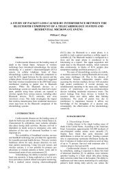
Distributed aerodynamic loads depend on <strong>the</strong> local angles <strong>of</strong> attack and <strong>the</strong>parameters <strong>of</strong> angular and linear velocity <strong>of</strong> <strong>the</strong> solid. Current parameters <strong>of</strong> <strong>the</strong>rotational and translational motion <strong>of</strong> <strong>the</strong> solid part <strong>of</strong> <strong>the</strong> equation (1,2) acting on<strong>the</strong> body forces and moments, and influence on <strong>the</strong> aerodynamic and o<strong>the</strong>rparameters <strong>of</strong> a non-stationary model <strong>of</strong> <strong>the</strong> object. Block diagram <strong>of</strong> <strong>the</strong> effect <strong>of</strong>aeroelasticity is presented in Figures 1 and 2.Changes in <strong>the</strong> distribution <strong>of</strong> mass <strong>of</strong> <strong>the</strong> object is associated with fuelconsumption, determines <strong>the</strong> change <strong>of</strong> coordinates <strong>of</strong> center <strong>of</strong> mass, which leadsto a change in <strong>the</strong> point <strong>of</strong> application <strong>of</strong> <strong>the</strong> moments <strong>of</strong> <strong>the</strong> aerodynamic forcesand engine thrust, center <strong>of</strong> mass.Dependence <strong>of</strong> model parameters on <strong>the</strong> parameters <strong>of</strong> motion and time arepredictable and can be represented in functional or tabular form. Uncertainty in <strong>the</strong>value <strong>of</strong> parameters derived from <strong>the</strong> natural or computational experiment can beconsidered as a range <strong>of</strong> parameter deviations from <strong>the</strong> nominal value. Theaerodynamic coefficients <strong>of</strong> sounding rocket c x , c z α , c y β , m z α , m y β , m y δy , m zδzareobtained using <strong>the</strong> finite element method (FEM). Computational experiment wascarried out using <strong>the</strong> s<strong>of</strong>tware package FLUENT for different Mach numbers.Varying <strong>the</strong> angles <strong>of</strong> attack α, sideslip angles β and roll angles γ at differentangular velocities p, q, r and angles <strong>of</strong> fin deflection δ x δ y δ z . They were differentfrom <strong>the</strong> experimental data obtained during test at <strong>the</strong> Nigerian Space Agency.<strong>On</strong> this basis, it is assumed that <strong>the</strong> dependence <strong>of</strong> aerodynamic coefficients,shown in Figure 3 and Figure 4 contain <strong>the</strong> multiplicative uncertainty is within10% (0.9 – 1.1 <strong>of</strong> <strong>the</strong> nominal value).Similarly, by comparing <strong>the</strong> results <strong>of</strong> field and numerical experiments usingprogram ANSYS defined uncertainty factors associated with elasticity.Multiplicative uncertainty in <strong>the</strong> values <strong>of</strong> natural frequencies and shapes <strong>of</strong> <strong>the</strong>flexural vibrations at certain points is also conventionally assumed to be 10%, asshown in Figure 1.9
Figure 1. Block diagram <strong>of</strong> <strong>the</strong> aeroelasticity modelChapter 3 <strong>of</strong> <strong>the</strong> dissertation work describes and analysis <strong>of</strong> <strong>the</strong> effect <strong>of</strong>flexibility on <strong>the</strong> design <strong>of</strong> <strong>the</strong> control system. The relationship between <strong>the</strong> rigidbody model <strong>of</strong> <strong>the</strong> sounding rocket and <strong>the</strong> model <strong>of</strong> elasticity via distributedaerodynamic forces is discussed. The so-called strip <strong>the</strong>ory as a first approximationis used. In this <strong>the</strong>ory, it is assumed that <strong>the</strong> local force is proportional to <strong>the</strong> localangle <strong>of</strong> attack.10
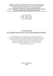
Figure 2. Block diagram <strong>of</strong> <strong>the</strong> model <strong>of</strong> local aerodynamic forcesFigure 3. Structure <strong>of</strong> <strong>the</strong> uncertainties in aerodynamic coefficients <strong>of</strong> <strong>the</strong> finsThe local angle <strong>of</strong> attack α ∗ i at a point with coordinate x i on <strong>the</strong> longitudinal axis<strong>of</strong> <strong>the</strong> vehicle taking into account flexible oscillation is given as:α ∗ i = α + X c−X iθ̇ − q ı ∂q+̇ i(6)V i V ı ∂x iwhere, ∂q iis <strong>the</strong> slope <strong>of</strong> elastic line in current time,∂xq̇i is <strong>the</strong> velocity <strong>of</strong> shape <strong>of</strong>ielastic line. V i is <strong>the</strong> local air velocity, α is <strong>the</strong> angle <strong>of</strong> attack <strong>of</strong> solid body, ρ is<strong>the</strong> air density, θ̇ is <strong>the</strong> angular velocity.11
Figure 4. Structure <strong>of</strong> <strong>the</strong> uncertainties in main aerodynamic coefficientsThe distributed aeroelastic force (F z (x)) along <strong>the</strong> longitudinal axis <strong>of</strong> <strong>the</strong>vehicle is evaluated as:F zi = ρ V i 2c ∗2ziα i (7)The effect <strong>of</strong> <strong>the</strong> appearance <strong>of</strong> elastic vibration in <strong>the</strong> feedback loop <strong>of</strong> <strong>the</strong>control system is connected with elastic translational and rotational movement <strong>of</strong><strong>the</strong> measuring system, <strong>the</strong> aerodynamic control surfaces and engine nozzle. Ama<strong>the</strong>matical model <strong>of</strong> sensors, taking into account <strong>the</strong> flexural vibrations <strong>of</strong>airframe (Elastic Sensors Subsystem) is shown in Figure 5.The sensors system includes models <strong>of</strong> measuring devices installed on <strong>the</strong> rocketbody, such as gyroscopes and accelerometers. They are presented in <strong>the</strong> form <strong>of</strong>transfer functions. If <strong>the</strong> elastic components <strong>of</strong> <strong>the</strong> input sensors (structuralfeedback) is ignored or not taken into account properly, <strong>the</strong>re are many instances,when self-exiting oscillation occurs on <strong>the</strong> body <strong>of</strong> <strong>the</strong> rocket. Increasing12
oscillation might lead to <strong>the</strong> destruction <strong>of</strong> <strong>the</strong> structure. Thus, <strong>the</strong> effect <strong>of</strong> elasticoscillations in <strong>the</strong> feedback loop must be addressed properly.Problems <strong>of</strong> dynamic interaction between <strong>the</strong> control system and elasticstructure depend on <strong>the</strong> location <strong>of</strong> <strong>the</strong> sensors, <strong>the</strong> distributed parameters <strong>of</strong>elasticity, <strong>the</strong> natural forms and frequencies, and damping characteristics. To solve<strong>the</strong>m, various attempts are used such as:1. Notch filters are used to suppress <strong>the</strong> resonant frequencies.2. Selection <strong>of</strong> favorable sensors locations.3. Increasing <strong>the</strong> numbers <strong>of</strong> sensorsMeasuring system occupies a key place in <strong>the</strong> development <strong>of</strong> control systemsand angular stabilization <strong>of</strong> elastic aircraft. The correct choice and placement <strong>of</strong> <strong>the</strong>sensors used are <strong>of</strong> great importance to improve <strong>the</strong> accuracy <strong>of</strong> regulation. Theuncertainty <strong>of</strong> <strong>the</strong> natural forms <strong>of</strong> <strong>the</strong> elastic component <strong>of</strong> <strong>the</strong> measuredparameters <strong>of</strong> motion in <strong>the</strong> longitudinal plane is taken into account in <strong>the</strong> model <strong>of</strong><strong>the</strong> sensors as shown in Figure 5.Figure 5. Model <strong>of</strong> <strong>the</strong> measuring system taking into account elasticityControl <strong>of</strong> sounding rocket is carried out by synchronous rotations <strong>of</strong> fouraerodynamic control surfaces that make up its fins. Model <strong>of</strong> <strong>the</strong> servo rudder ispresented in <strong>the</strong> form <strong>of</strong> transfer function (Fig. 6). The deflection <strong>of</strong> aerodynamiccontrol surfaces give rise to aerodynamic forces and moments, which mustcompliance with <strong>the</strong> specified control law.Deflection and rotation <strong>of</strong> <strong>the</strong> elastic line at <strong>the</strong> point <strong>of</strong> rotation <strong>of</strong> <strong>the</strong> rudders,as well as at <strong>the</strong> application point <strong>of</strong> <strong>the</strong> thrust vector <strong>of</strong> <strong>the</strong> solid motor leads toadditional aerodynamic loads on <strong>the</strong> rocket body, which in turn leads to itsdeformation. Effect <strong>of</strong> bending strain in <strong>the</strong> longitudinal plane on <strong>the</strong> action <strong>of</strong> <strong>the</strong>rudders and thrust with <strong>the</strong> uncertainty <strong>of</strong> natural forms is shown in Figure 6.13
Figure 6. Block diagram <strong>of</strong> <strong>the</strong> effect <strong>of</strong> elasticity in <strong>the</strong> model <strong>of</strong> servo actuator <strong>of</strong>aerodynamic rudders a) and models <strong>of</strong> engine thrust b)The set values <strong>of</strong> uncertainties, which correspond to <strong>the</strong> results <strong>of</strong> comparison <strong>of</strong>individual natural and computational experiments, can be changed at <strong>the</strong> designcontrol system, for example to compensate for <strong>the</strong> effect <strong>of</strong> manifestations in <strong>the</strong>feedback loop. In this case, <strong>the</strong> nominal value <strong>of</strong> <strong>the</strong>ir own forms <strong>of</strong> flexuralvibrations and <strong>the</strong> range <strong>of</strong> variation defined by <strong>the</strong> syn<strong>the</strong>sis problem.Chapter 4 <strong>of</strong> <strong>the</strong> dissertation work describes <strong>the</strong> procedure for <strong>the</strong> design <strong>of</strong> <strong>the</strong>robust controller for <strong>the</strong> sounding rocket. The procedure <strong>of</strong> linearization <strong>of</strong> <strong>the</strong>model <strong>of</strong> <strong>the</strong> object at <strong>the</strong> given points <strong>of</strong> nominal trajectory was described. Theselection from <strong>the</strong> full model <strong>of</strong> <strong>the</strong> spatial motion only <strong>the</strong> rotational motion in <strong>the</strong>pitch plane taking into account flexural vibrations was carried out. Presentation <strong>of</strong>a linear model in <strong>the</strong> form containing <strong>the</strong> nominal system model and a unifiedmodel <strong>of</strong> all <strong>the</strong> uncertainties was addressed. The question <strong>of</strong> <strong>the</strong> application <strong>of</strong> H ∞method in combination with μ - syn<strong>the</strong>sis and analysis was addressed.A complete description <strong>of</strong> open-loop system that includes a model <strong>of</strong>longitudinal motion <strong>of</strong> <strong>the</strong> rocket, taking into account <strong>the</strong> elasticity model, servoand sensor model is defined as <strong>the</strong> upper linear transformation (LFT).Parameters <strong>of</strong> <strong>the</strong> nominal model G are calculated for a series <strong>of</strong> points <strong>of</strong>reference trajectories. State vector <strong>of</strong> <strong>the</strong> nominal model contains <strong>the</strong> variables in<strong>the</strong> equation <strong>of</strong> rigid body dynamics, actuator state variables and state variablesmodel <strong>of</strong> elasticity (elastic vibration modes). For special conditions such as zerospeed or angle <strong>of</strong> attack, some variables <strong>of</strong> <strong>the</strong> state vector and certain parameters<strong>of</strong> uncertainty does not appear and can be excluded from <strong>the</strong> model. Aerodynamicmodel for <strong>the</strong> longitudinal motion <strong>of</strong> a rigid body contains five undeterminedcoefficients:c i = c x , c α δz , cyz, m ωy y , m δy y , i = 1 … 5αwhere c x is <strong>the</strong> aerodynamic drag force coefficient <strong>of</strong> <strong>the</strong> body and fins, c z is <strong>the</strong>δaerodynamic lift force coefficients due to <strong>the</strong> angle <strong>of</strong> attack, cyzis <strong>the</strong>14
aerodynamic lift force coefficient due to <strong>the</strong> deflection <strong>of</strong> <strong>the</strong> fin in <strong>the</strong> y-direction,m y ωy is <strong>the</strong> aerodynamic damping moment coefficient due to yaw rates ω y andm y δy is <strong>the</strong> aerodynamic control moment coefficient due to <strong>the</strong> fin deflection in <strong>the</strong>y-direction.For <strong>the</strong> simulation <strong>of</strong> <strong>the</strong> flexible model considering only <strong>the</strong> first three modes <strong>of</strong>flexible oscillation, 12 coefficients <strong>of</strong> variation are added to <strong>the</strong> model namely,c i = c ω1 , c ω2 , c ω3 , c a , c g , c F , c T , i = 6 … 12where c ω1 , c ω2 , c ω3 are coefficients <strong>of</strong> variation <strong>of</strong> <strong>the</strong> natural frequencies <strong>of</strong> <strong>the</strong>first, second and third modes respectively, c a , c g , c F and c T are <strong>the</strong> coefficients <strong>of</strong>variation <strong>of</strong> <strong>the</strong> accelerometer data, gyroscope data, angle <strong>of</strong> desired fin deflectionand magnitude <strong>of</strong> thrust respectively due to structural feedback phenomena.These coefficients can be represented in <strong>the</strong> form:c = c̅ (1 + p c δ c ) (8)where p c is <strong>the</strong> relative uncertainty, c̅ is <strong>the</strong> nominal value <strong>of</strong> c and δ c is <strong>the</strong> normbound <strong>of</strong> <strong>the</strong> uncertainty coefficient. In this research <strong>the</strong> relative uncertainty isassigned as 10% and <strong>the</strong> norm bound:−1 ≤ δ c ≤ 1 (9)The uncertainty coefficient can also be presented in <strong>the</strong> form <strong>of</strong> upper linearfractional transformation:c = F U (M c , δ c ) (10)where M c = 0 cp c c (11)Figure 7. Structure <strong>of</strong> uncertainties in <strong>the</strong> form <strong>of</strong> LFTUncertainty coefficients can be isolated from <strong>the</strong> model in a separate uncertaintyblock ∆. The uncertainty block Δ is <strong>the</strong> diagonal <strong>of</strong> all <strong>the</strong> coefficients <strong>of</strong> variation<strong>of</strong> <strong>the</strong> model under investigation and consists <strong>of</strong> normalized parameter uncertaintywith zero nominal value and range <strong>of</strong> change from -1 to +1.Δ = diag(δ ci ) (12)The model <strong>of</strong> a system in <strong>the</strong> form <strong>of</strong> upper LFT F U (G, ∆) is shown in Figure 8.15
Figure 8. Structure <strong>of</strong> model <strong>of</strong> a system in <strong>the</strong> form <strong>of</strong> LFTInput signal u corresponds to <strong>the</strong> control signal, applied to <strong>the</strong> servo actuator,output signal θ′ - <strong>the</strong> measured angular velocity in pitch plane, output signal n z -measured vertical acceleration associated with <strong>the</strong> coordinate system.The designed control system must ensure <strong>the</strong> angular stabilization in <strong>the</strong> pitchplane and testing <strong>of</strong> <strong>the</strong> given control law according to <strong>the</strong> normal acceleration in<strong>the</strong> presence <strong>of</strong> random external disturbances and noises.Block diagram <strong>of</strong> <strong>the</strong> closed-loop system in Figure 9 including feedback controllerK as well as blocks reflecting <strong>the</strong> uncertainty <strong>of</strong> <strong>the</strong> model and weighting functionsassociated with <strong>the</strong> implementation <strong>of</strong> performance requirements for closed-loopsystem.Figure 9. Block diagram <strong>of</strong> <strong>the</strong> closed-loop system for H ∞ syn<strong>the</strong>sisThe system has a reference signal r, noises η a and η g on measurement <strong>of</strong> n y andθ̇, respectively, and two weighted outputs e p , and e u that characterise performancerequirements. The transfer functions W a and W g represent <strong>the</strong> dynamics <strong>of</strong> <strong>the</strong>16
accelerometer measuring n y , and <strong>the</strong> dynamics <strong>of</strong> <strong>the</strong> rate gyro measuring θ̇respectively. The coefficient K a is <strong>the</strong> accelerometer gain.The high frequency noises η a and η g occurred in measuring <strong>the</strong> normalacceleration and <strong>the</strong> derivative <strong>of</strong> <strong>the</strong> pitch angle, and satisfy <strong>the</strong> conditions:‖η a ‖ 2 ≤ 1, η g ≤ 1. Weighting function W p is chosen for amplification <strong>of</strong> <strong>the</strong>2mismatch signal e p in <strong>the</strong> low frequencies.Initially, to find <strong>the</strong> transfer function <strong>of</strong> <strong>the</strong> controller K <strong>the</strong> suboptimal H ∞syn<strong>the</strong>sis procedure is used. The standard configuration <strong>of</strong> <strong>the</strong> system for H ∞syn<strong>the</strong>sis is shown in Figure 9, where w denotes <strong>the</strong> external input signals, z –output signals, which must be minimized, y – <strong>the</strong> vector <strong>of</strong> available measuredcontroller K and u – vector <strong>of</strong> control signals.а) b) с)Figure 10. Standard system configuration for H ∞ syn<strong>the</strong>sis (a) and for μ - syn<strong>the</strong>sis(b) and (c)Block P(s) is called <strong>the</strong> generalized plant or interconnected system, when ∆ = 0(Figure 9), taking into consideration that:z = col(e p , e u ), w = col(r, η a , η g ), y= col(y1, y2) (13)The generalized model <strong>of</strong> system can be presented in <strong>the</strong> form:P(s) = P 11(s) P 12 (s)P 21 (s) P 22 (s) (14)z = [P 11 + P 12 K(I − P 22 K) −1 P 21 ] w = : F l (P, K)w (15)where F l (P, K) is <strong>the</strong> lower linear fractional transformation <strong>of</strong> P and K.The design objective is to find a stabilizing controller K such that <strong>the</strong> H ∞ -norm<strong>of</strong> <strong>the</strong> closed-loop transfer function is less than a given positive number, i.e.,‖F l (P, K)‖ ∞ < γ (16)where17
γ > γ 0 ≔ min Kstabilizing ‖F l (P, K)‖ ∞ (17)The optimal solution is to find during iterations decrement <strong>of</strong> <strong>the</strong> given numberγ. The result <strong>of</strong> <strong>the</strong> syn<strong>the</strong>sis <strong>of</strong> <strong>the</strong> H ∞ controller is given in chapter 5 <strong>of</strong> thiswork. Experience has shown that <strong>the</strong> H ∞ controller guarantees robust stability andnot robust performance. Such is <strong>the</strong> case in this research; analysis <strong>of</strong> <strong>the</strong> robustcharacteristics <strong>of</strong> <strong>the</strong> designed controller confirms <strong>the</strong> above statement. To obtainbetter result, µ syn<strong>the</strong>sis is combined with H ∞ infinity.Stability <strong>of</strong> <strong>the</strong> system with fixed controller and various kinds <strong>of</strong> uncertaintiescan be investigated using μ-analysis. For <strong>the</strong> systems with M/∆-configuration forall perturbations ‖∆(s)‖ ∞ < γ <strong>of</strong> a given structure, robust stability holds if andonly ifsup ω≥0 µ(M(jω)) ≤ 1 γ(18)where μ(M) is structured singular value for <strong>the</strong> system M = F l (P, K).Solution <strong>of</strong> <strong>the</strong> problem <strong>of</strong> choosing <strong>the</strong> optimal controller, which ensures that<strong>the</strong> condition (18) is found by <strong>the</strong> μ-syn<strong>the</strong>sis. Considering <strong>the</strong> requirements for <strong>the</strong>dynamic characteristics <strong>of</strong> a closed-loop system in <strong>the</strong> syn<strong>the</strong>sis allows <strong>the</strong> addition<strong>of</strong> a fictitious uncertainty block ∆ F to <strong>the</strong> block <strong>of</strong> parametric uncertainties in <strong>the</strong>model (Figure 10.c).Thus, <strong>the</strong> problem boils down to <strong>the</strong> choice <strong>of</strong> <strong>the</strong> regulator, providing <strong>the</strong>fulfillment <strong>of</strong> <strong>the</strong> condition (18), and <strong>the</strong> problem <strong>of</strong> maximum robustness (i.e.finding <strong>the</strong> maximum γ , for which robust stability can be ensured) to minimumM(P, K)(jω) for К:inf K(s) sup ωϵR µ[M(P, K)(jω)] (19)There is no direct method for solving this optimization problem. In practice, <strong>the</strong>method <strong>of</strong> solution is called DK iteration. Although <strong>the</strong> DK iteration proceduredoes not guarantee convergence, but in most cases, converges to <strong>the</strong> minimumvalue <strong>of</strong> μ.The procedures <strong>of</strong> H ∞ and μ-syn<strong>the</strong>sis are implemented for <strong>the</strong> extended model<strong>of</strong> sounding rockets, taking into account all <strong>the</strong> above uncertainties andrequirements for dynamic characteristics <strong>of</strong> <strong>the</strong> system using <strong>the</strong> standard features<strong>of</strong> <strong>the</strong> MATLAB Robust Toolbox package.Chapter 5 gives <strong>the</strong> analysis <strong>of</strong> <strong>the</strong> results <strong>of</strong> <strong>the</strong> design <strong>of</strong> <strong>the</strong> controller using<strong>the</strong> H ∞ method in combination with μ-syn<strong>the</strong>sis. Firstly a controller is designed for<strong>the</strong> rigid rocket body using <strong>the</strong> H ∞ sub-optimal method and μ-syn<strong>the</strong>sis approach.The design and simulation <strong>the</strong> controller using <strong>the</strong> H ∞ sub-optimal method incombination with µ syn<strong>the</strong>sis is carried for forty second <strong>of</strong> flight duration. Theresults obtained for <strong>the</strong> controller design using for <strong>the</strong> rigid body model H ∞ sub-18
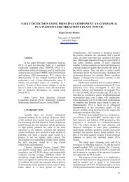
optimal approach is compared with <strong>the</strong> results <strong>of</strong> controller design using <strong>the</strong> µ-syn<strong>the</strong>sis approach for <strong>the</strong> same rigid body dynamics without taking <strong>the</strong> effect <strong>of</strong>flexibility and aeroserv<strong>of</strong>lexibility into consideration. This is to prove that <strong>the</strong> µ-syn<strong>the</strong>sis controller gives a better robust performance for <strong>the</strong> same set <strong>of</strong> boundeduncertainties than a H ∞ sub-optimal controller (Figure 11) although bothcontrollers guarantees robust stability criteria (Figure 12).2.5ROBUST PERFORMANCE0.45ROBUST PERFORMANCE0.4mu21.510.5mu0.350.30.250.20.150.10.05010 -3 10 -2 10 -1 10 0 10 1 10 2Frequency (rad/s)010 -3 10 -2 10 -1 10 0 10 1 10 2Frequency (rad/s)Fig. 11 Robust performance characteristics <strong>of</strong> H ∞ controller-left, µ -controller <strong>right</strong>10 0 ROBUST STABILITY10 0 ROBUST STABILITY10 -210 -110 -410 -2mumu10 -610 -310 -810 -410 -1010 -3 10 -2 10 -1 10 0 10 1 10 2Frequency (rad/s)Fig. 12 Robust stability characteristics <strong>of</strong> H ∞ controller-left, µ -controller <strong>right</strong>Next, <strong>the</strong> simulation <strong>of</strong> <strong>the</strong> sounding rocket model taking into consideration <strong>the</strong>flexibility and aeroserv<strong>of</strong>lexibility effects <strong>of</strong> <strong>the</strong> first 3 modes <strong>of</strong> flexibleoscillations is carried out using <strong>the</strong> µ-syn<strong>the</strong>sis method.The results obtained for <strong>the</strong>µ-controller designed for <strong>the</strong> rigid body dynamics and µ-controller designed forflexible body dynamics are <strong>the</strong>n compared (Figure 13, 14, 15).Emphases are placed on <strong>the</strong> comparisons <strong>of</strong> <strong>the</strong> following characteristics, <strong>the</strong>transient responses <strong>of</strong> <strong>the</strong> closed loop system with <strong>the</strong> design µ controller for a step1910 -510 -3 10 -2 10 -1 10 0 10 1 10 2Frequency (rad/s)
signal with magnitude ±15g which corresponds to a change in <strong>the</strong> normalacceleration n z with ±15g, <strong>the</strong> angle <strong>of</strong> deflection δ z <strong>of</strong> control fins in <strong>the</strong> closedloop system and frequency responses <strong>of</strong> <strong>the</strong> closed loop system with respect to <strong>the</strong>designed μ controller.From Figure 11 it is clear that <strong>the</strong> robust performance characteristics <strong>of</strong> <strong>the</strong>closed loop system is not guaranteed with <strong>the</strong> design H-infinity controller(maximum value <strong>of</strong> <strong>the</strong> structured singular value frequency response, SSV isgreater than 1), but <strong>the</strong> mu-controller guarantees robust performance for <strong>the</strong> sameset <strong>of</strong> bounded uncertainties, SSV is less than 1. Since <strong>the</strong> mu controller givesbetter robust performance for <strong>the</strong> same set <strong>of</strong> uncertainties, <strong>the</strong> mu syn<strong>the</strong>sis andanalysis approach is fur<strong>the</strong>r used in <strong>the</strong> design <strong>of</strong> <strong>the</strong> controller for <strong>the</strong> flexibilitymodel <strong>of</strong> <strong>the</strong> sounding rocket. The first 3 modes <strong>of</strong> flexible oscillation weresimulated and <strong>the</strong> results <strong>of</strong> <strong>the</strong> simulation are compared with <strong>the</strong> results for <strong>the</strong> mucontroller designed for <strong>the</strong> rigid body model.From Figure 13 <strong>the</strong> transient response <strong>of</strong> <strong>the</strong> closed loop system with <strong>the</strong>designed mu controller for both <strong>the</strong> rigid model (<strong>right</strong>) and flexible model (left) isillustrated. The overshoot for <strong>the</strong> same reference signal for both controllers isunder 25% and <strong>the</strong> settling time about 3 seconds.20Response in n y25Response in n y152010151055n y(g)0n y(g)0-5-5-10-10-15-15-20-200 1 2 3 4 5 6 7 8 9Time (secs)-250 1 2 3 4 5 6 7 8 9Time (secs)Fig. 13 Transient response in n y for RM –left and for FM – <strong>right</strong>Figure 14 illustrate <strong>the</strong> closed loop angle <strong>of</strong> control fin deflection δ z . The angleis about 18 degrees for <strong>the</strong> rigid body model and 8 degrees for <strong>the</strong> flexible model.20
0.25Closed-loop control and Fins deflection0.4Closed-loop control and Fins deflectionControl δ o0.20.15Control δ oFins δ0.30.2Fins δδ o (rads)0.10.050-0.05δ o (rads)0.10-0.1-0.1-0.15-0.2-0.2-0.3-0.250 1 2 3 4 5 6 7 8 9Time (secs)-0.40 1 2 3 4 5 6 7 8 9Time (secs)Fig. 14 Closed loop control and fin deflection for RM-left and for FM-<strong>right</strong>The closed loop magnitude plot shown in Figure 15 shows that over <strong>the</strong> lowfrequency region <strong>the</strong> magnitude response is close to 1 i.e. <strong>the</strong> reference signal canbe followed accurately. The closed loop system bandwidth is about 3 rad/sec. Theresults <strong>of</strong> <strong>the</strong> simulation obtained attest to <strong>the</strong> validity <strong>of</strong> <strong>the</strong> uncertainty modelused.20Closed-loop magnitude plot20Closed-loop magnitude plot00-20-20Magnitude (dB)-40Magnitude (dB)-40-60-60-80-80-10010 -1 10 0 10 1 10 2 10 3Frequency (rad/s)-10010 -1 10 0 10 1 10 2 10 3Frequency (rad/s)Fig. 15 Closed loop magnitude plot for RM-left and for FM-<strong>right</strong>21
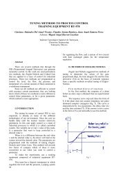
Fig. 16 Fragment <strong>of</strong> <strong>the</strong> GUI s<strong>of</strong>tware developed for simulation <strong>of</strong> rocket dynamicsIn this research a graphical user interface (GUI) s<strong>of</strong>tware was developed usingMatlab (Figure 16). The GUI s<strong>of</strong>tware allows for easy simulation and analysis <strong>of</strong><strong>the</strong> rocket dynamics for different models. The flow chart <strong>of</strong> <strong>the</strong> overall simulationprocess is presented in Fig. 17. It will be <strong>of</strong> great assistance for control designengineering students in various institutions <strong>of</strong> higher learning, particular students<strong>of</strong> <strong>the</strong> State University <strong>of</strong> Aerospace Instrumentation in Saint Petersburg. Thedeveloped s<strong>of</strong>tware would also be <strong>of</strong> immense benefit to entire technical staff <strong>of</strong><strong>the</strong> National Space Research and Development Agency in Nigeria.22
Start6-DoF rigid body modelWeighting functionsselectionFlexibilitymodel needed ?Robust controller designFlexibility model <strong>of</strong> <strong>the</strong>first three modesMeetrequirements ?Rigid modeluncertainty blockController reductionFlexibility modeluncertainty blockMeetrequirements ?Local linearizationFigure 17 Flow chart <strong>of</strong> <strong>the</strong> simulation processConclusions1. In modeling <strong>of</strong> <strong>the</strong> uncertainties, it is necessary to simplify <strong>the</strong> model as muchas possible in order to avoid errors in linear approximation during <strong>the</strong>application <strong>of</strong> linear <strong>of</strong> linear robust control system design techniques for anonlinear plant.2. The uncertainty model derived for <strong>the</strong> flexible sounding rocket system containsreal parametric uncertainties in a highly structured form. Such a model appealto <strong>the</strong> application <strong>of</strong> µ-syn<strong>the</strong>sis and analysis method having been usedextensively to syn<strong>the</strong>size a number <strong>of</strong> control laws for several different flexiblestructure experiments with great success.3. Both <strong>the</strong> H-Infinity and µ-controllers guarantees robust stability <strong>of</strong> <strong>the</strong>corresponding closed loop system but <strong>the</strong> H-Infinity controller does notguarantee robust performance for a set <strong>of</strong> bounded uncertainties, which makes23End
it necessary to combine it with µ-syn<strong>the</strong>sis to achieve better results in terms <strong>of</strong>robust performance for <strong>the</strong> same set <strong>of</strong> uncertainty bound.4. The nonlinear simulation results confirm <strong>the</strong> ability <strong>of</strong> <strong>the</strong> µ-controller toachieve disturbance attenuation and good responses to reference signals. Thesimulation confirms <strong>the</strong> validity <strong>of</strong> <strong>the</strong> uncertainty model used.5. The µ-controller may be used for various trajectories and Mach numbers.However, in order to control <strong>the</strong> rocket efficiently through <strong>the</strong> whole flightenvelope it may be necessary to implement several controller design fordifferent flight conditions.6. It is possible to reduced <strong>the</strong> controller order to as low as 10 without distorting<strong>the</strong> dynamics <strong>of</strong> <strong>the</strong> nonlinear closed loop system.7. Better characteristics in terms <strong>of</strong> frequency and time responses <strong>of</strong> <strong>the</strong> closedloop system for <strong>the</strong> designed µ-controller can be achieved by tuning <strong>the</strong>weighting functions.Publications1. Аро Х.О. Применение методологии робастного синтеза к системеугловой стабилизации метеорологической ракеты. Известия вузов –Приборостроение, Санкт-Петербург, №11, 2011 (рецензируемыйнаучный журнал из Перечня ВАК, принято к публикации).2. Аро Х.О. Метод робастного синтеза аэрокосмического аппарата.Гироскопия и навигация, №3 (66), 2009, с.86 (рецензируемый научныйжурнал из Перечня ВАК).3. Аро Х.О. Разработка низкостоимостной интегрированнойнавигационной системы для метеорологической ракеты. Гироскопияи навигация, №3 (70), 2010, с.97 (рецензируемый научный журнал изПеречня ВАК).4. <strong>Aro</strong> H.O., Adetoro L.M. Review <strong>of</strong> Nigerian Space Programs. Proceedings <strong>of</strong><strong>the</strong> annual Scientific Conference <strong>of</strong> SUAI. Saint Petersburg, Russia. 2009.5. <strong>Aro</strong> H.O., Adetoro L.M. Nigeria Space Programs. International ScientificRussian-American Journal, Actual Problems <strong>of</strong> Aviation and AerospaceSystems. Kazan, Daytona Beach, vol. 2(29). 2009.6. <strong>Aro</strong> H.O. Robust Control Approach <strong>of</strong> Aerospace Vehicle. Proceedings <strong>of</strong> <strong>the</strong>16 th Saint Petersburg International Conference on Integrated NavigationSystems. Saint Petersburg, Russia. 2009.7. <strong>Aro</strong> H.O. Investigating <strong>the</strong> Robust methods used in Controlling Non-stationary,Nonlinear Flexible Object. Proceedings <strong>of</strong> <strong>the</strong> IFAC Workshop on Aerospace,Guidance, Navigation and Control Systems. Samara, Russia. 2009.24
8. <strong>Aro</strong> H.O., Brodsky .S. A., Adetoro L.M. Intelligent Approach to ExperimentalEstimation <strong>of</strong> Flexible Aerospace Vehicle Parameters. Proceedings <strong>of</strong> 2 nd IFACInternational conference on Intelligent Control Systems and Signal Processing,ICON, Istanbul. 2009.9. <strong>Aro</strong> H.O. Algorithms for Robust Control <strong>of</strong> Flexible Flying Vehicle.Proceedings <strong>of</strong> <strong>the</strong> annual Scientific Conference <strong>of</strong> SUAI. Saint Petersburg,Russia. 2011.10. <strong>Aro</strong> H.O. Development <strong>of</strong> a Low-Cost Strap-down Integrated INS/GPS forSounding Rocket. Proceedings <strong>of</strong> <strong>the</strong> 17 th Saint Petersburg InternationalConference on Integrated Navigation Systems. Saint Petersburg, Russia. 2010.11. Аро Х.О. Влияние нежесткости корпуса на систему управленияметеорологической ракетой. Научная сессия ГУАП: Сб. докл.: В 3 ч. Ч.I.Технические науки/ СПб.: ГУАП, 2011. (принято к публикации).12. <strong>Aro</strong> H.O. Application <strong>of</strong> Robust Control Methodology for Sounding RocketAttitude Stabilization. Proceedings <strong>of</strong> <strong>the</strong> 5 th International Conference onRecent Advances in Space Technologies, Istanbul, 2011.25