Pneumatic Seals Contents General information Part I ... - Dilanda.it
Pneumatic Seals Contents General information Part I ... - Dilanda.it
Pneumatic Seals Contents General information Part I ... - Dilanda.it

Create successful ePaper yourself
Turn your PDF publications into a flip-book with our unique Google optimized e-Paper software.
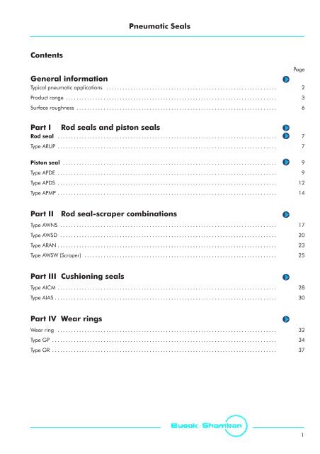
<strong>Pneumatic</strong> <strong>Seals</strong><strong>Contents</strong><strong>General</strong> <strong>information</strong>Typical pneumatic applications . . . . . . . . . . . . . . . . . . . . . . . . . . . . . . . . . . . . . . . . . . . . . . . . . . . . . . . . . . . . . . . . . . . . . . . 2Product range . . . . . . . . . . . . . . . . . . . . . . . . . . . . . . . . . . . . . . . . . . . . . . . . . . . . . . . . . . . . . . . . . . . . . . . . . . . . . . . . . . . . . . 3Surface roughness . . . . . . . . . . . . . . . . . . . . . . . . . . . . . . . . . . . . . . . . . . . . . . . . . . . . . . . . . . . . . . . . . . . . . . . . . . . . . . . . . . 6Page<strong>Part</strong> IRod seals and piston sealsRod seal . . . . . . . . . . . . . . . . . . . . . . . . . . . . . . . . . . . . . . . . . . . . . . . . . . . . . . . . . . . . . . . . . . . . . . . . . . . . . . . . . . . . . . . . . 7Type ARUP . . . . . . . . . . . . . . . . . . . . . . . . . . . . . . . . . . . . . . . . . . . . . . . . . . . . . . . . . . . . . . . . . . . . . . . . . . . . . . . . . . . . . . . . . 7Piston seal . . . . . . . . . . . . . . . . . . . . . . . . . . . . . . . . . . . . . . . . . . . . . . . . . . . . . . . . . . . . . . . . . . . . . . . . . . . . . . . . . . . . . . . 9Type APDE . . . . . . . . . . . . . . . . . . . . . . . . . . . . . . . . . . . . . . . . . . . . . . . . . . . . . . . . . . . . . . . . . . . . . . . . . . . . . . . . . . . . . . . . . 9Type APDS . . . . . . . . . . . . . . . . . . . . . . . . . . . . . . . . . . . . . . . . . . . . . . . . . . . . . . . . . . . . . . . . . . . . . . . . . . . . . . . . . . . . . . . . 12Type APMP . . . . . . . . . . . . . . . . . . . . . . . . . . . . . . . . . . . . . . . . . . . . . . . . . . . . . . . . . . . . . . . . . . . . . . . . . . . . . . . . . . . . . . . . 14<strong>Part</strong> IIRod seal-scraper combinationsType AWNS . . . . . . . . . . . . . . . . . . . . . . . . . . . . . . . . . . . . . . . . . . . . . . . . . . . . . . . . . . . . . . . . . . . . . . . . . . . . . . . . . . . . . . . 17Type AWSD . . . . . . . . . . . . . . . . . . . . . . . . . . . . . . . . . . . . . . . . . . . . . . . . . . . . . . . . . . . . . . . . . . . . . . . . . . . . . . . . . . . . . . . 20Type ARAN . . . . . . . . . . . . . . . . . . . . . . . . . . . . . . . . . . . . . . . . . . . . . . . . . . . . . . . . . . . . . . . . . . . . . . . . . . . . . . . . . . . . . . . . 23Type AWSW (Scraper) . . . . . . . . . . . . . . . . . . . . . . . . . . . . . . . . . . . . . . . . . . . . . . . . . . . . . . . . . . . . . . . . . . . . . . . . . . . . . . 25<strong>Part</strong> III Cushioning sealsType AICM . . . . . . . . . . . . . . . . . . . . . . . . . . . . . . . . . . . . . . . . . . . . . . . . . . . . . . . . . . . . . . . . . . . . . . . . . . . . . . . . . . . . . . . . 28Type AIAS . . . . . . . . . . . . . . . . . . . . . . . . . . . . . . . . . . . . . . . . . . . . . . . . . . . . . . . . . . . . . . . . . . . . . . . . . . . . . . . . . . . . . . . . . 30<strong>Part</strong> IV Wear ringsWear ring . . . . . . . . . . . . . . . . . . . . . . . . . . . . . . . . . . . . . . . . . . . . . . . . . . . . . . . . . . . . . . . . . . . . . . . . . . . . . . . . . . . . . . . . 32Type GP . . . . . . . . . . . . . . . . . . . . . . . . . . . . . . . . . . . . . . . . . . . . . . . . . . . . . . . . . . . . . . . . . . . . . . . . . . . . . . . . . . . . . . . . . . 34Type GR . . . . . . . . . . . . . . . . . . . . . . . . . . . . . . . . . . . . . . . . . . . . . . . . . . . . . . . . . . . . . . . . . . . . . . . . . . . . . . . . . . . . . . . . . . 371
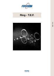
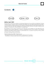
<strong>Pneumatic</strong> CylinderAWNSARANGRGPAIASAICMAPDEAPDSFigure 1Typical pneumatic cylinder w<strong>it</strong>h B+S seals2
Sealing solutions in polyurethane for <strong>Pneumatic</strong>sTable IRod seals - selection cr<strong>it</strong>eriaSeal Application Installation Technical data* MaterialType Page Field of application Function RangemmGroove typecorrespondingto mmC**Speedm/sTemperaturePressureMpaStandardsealmaterialARUP7Industrial <strong>Pneumatic</strong>sStandard Cylinderssingleacting3-100 closed -30 to+801 1.6 WU9E1Table II Piston seals - selection cr<strong>it</strong>eriaSeal Application Installation Technical data* MaterialType Page Field of application Function RangemmGroove typecorrespondingto mmTemperatureC**Speedm/sPressureMpaStandardsealmaterialAPDE9Industrial <strong>Pneumatic</strong>sStandard Cylinderssingleacting 6-200 closed -30 to+801 1.6 WU9E1APDS12Industrial <strong>Pneumatic</strong>sStandard Cylinderssingleacting 6-40 closed -30 to+801 1.6 WU9E1APMP14Industrial <strong>Pneumatic</strong>sShort stroke magneticand non magneticcylinderssingleordoubleacting8-100 open -30 to+801 1.6 WU9E1* The data below are maximum values and cannot be used at the same time. The max. pressure depends on temperature and gap dimension.** For applications at low temperatures below -30 C and at high temperatures +80 C, please contact us.3
Sealing solutions in polyurethane for <strong>Pneumatic</strong>sTable IIIRod seals and rod seal-scraper combinationsScraper Application Installation Technical data* MaterialType Page Field of application Function RangemmGroove typecorrespondingto mmTemperatureC**Speedm/sPressureMpaStandardsealmaterialAWNS17Industrial <strong>Pneumatic</strong>sStandard Cylindersdoubleacting 3-70 closed -30 to+801 1.6 WU9E1AWSD20Industrial <strong>Pneumatic</strong>sStandard Cylindersdoubleacting 4-100 closed -30 to+801 1.6 WU9E1ARAN23Industrial <strong>Pneumatic</strong>sStandard Cylindersdoubleacting 12-63 open -30 to+801 1.6 WU9E1AWSW25Industrial <strong>Pneumatic</strong>sStandard Cylinderssingleacting 6-60 open -30 to+802 1.6 WU9E1* The data below are maximum values and cannot be used at the same time. The max. pressure depends on temperature and gap dimension.** For applications at low temperatures below -30 C and at high temperatures +80 C, please contact us.4
Sealing solutions in polyurethane for <strong>Pneumatic</strong>sTable IVCushioning seals - selection cr<strong>it</strong>eriaCushioningsealsApplication Installation Technical data* MaterialType Page Field of application Function RangemmGroove typecorrespondingto mmTemperatureC**Speedm/sPressureMpaAICM28Industrial <strong>Pneumatic</strong>sStandard Cylinderscushioning 6-50 closed -30 to+801 1.6 WU9E1AIAS30Industrial <strong>Pneumatic</strong>sStandard Cylinderscushioning 10-50 closed -30 to+801 1.6 WU9E1Table VWear rings - selection cr<strong>it</strong>eriaWear Ring Application Installation Technical data* MaterialType Page Field of application Function RangemmGroove typecorrespondingto mmTemperatureC**Speedm/sPressureMpaGP34Industrial <strong>Pneumatic</strong>sStandard CylindersPistonWearRing8-250 closed -40 to+1101 - POMGR37Industrial <strong>Pneumatic</strong>sStandard CylindersRodWearRing8-50 closed -40 to+1101 - POM* The data below are maximum values and cannot be used at the same time. The max. pressure depends on temperature and gap dimension.** For applications at low temperatures below -30 C and at high temperatures +80 C, please contact us.5
Surface roughnessSurface roughness DIN EN ISO 4287The functional reliabil<strong>it</strong>y and service life of a seal dependto a very great extent on the qual<strong>it</strong>y and surface finish ofthe mating surface to be sealed.Scores, scratches, pores, concentric or spiral machiningmarks are not perm<strong>it</strong>ted. Higher demands must be madeon the surface finish of dynamic surfaces than of staticmating surfaces.The characteristics most frequently used to describe thesurface microfinish Ra a , R z and R max are defined in DINEN ISO 4287. These characterics alone, however, are notsufficient for assessing the su<strong>it</strong>abil<strong>it</strong>y in seal technology. Inadd<strong>it</strong>ion the material contact area of the surfaceroughness profile R mr in accordance w<strong>it</strong>h DIN EN ISO4287 should be demanded. The significance ot thissurface specification is illustrated in Fig. 4. It shows clearlythat specification of R a and R z alone does not describe thesurface roughness profile accurately enough for the sealtechnology and is thus not sufficient for assessing thesu<strong>it</strong>abil<strong>it</strong>y. The material contact area R mr is essential forassessing surfaces, as this parameter is determined by thespecific surface roughness profile. This in turn is directlydependent on the machining process employed.Busak + Shamban recommends that the followingsurface finishes be observed:Surface profileclosed profile formopen profile formFigure 2Profile forms of surfacesR a R z R mr0.1 1.0 70%0.2 1.0 15%Figure 4 shows two surface profiles, both of which exhib<strong>it</strong>nearly the same value for R z in the test procedure. Thedifference becomes obvious only when the materialcontact area of the survace roughness profiles arecompared. These show that the upper roughness profilew<strong>it</strong>h R mr = 70% has the better seal/mating surface ratio.Table VSurface roughnessSurface roughness mParameterMating surfaceGroovePolyurethanesurfaceR max 1.00 - 4.00 < 16.0R z DIN 0.63 - 2.50 < 10.0R a 0.10 - 0.40 < 1.6The material contact area R mr should be approx. 50 to70%, determined at a cut depth c = 0.25 x R z , relative toa reference line of C ref. 5%.6
Rod Seal - Type ARUPRod seal type ARUPDescriptionThe ARUP rod seal has been redesigned w<strong>it</strong>h respect tothe trad<strong>it</strong>ional u-profile used in pneumatics to givesignificant improvements.These include: A dynamic lip w<strong>it</strong>h no sharp edges to facil<strong>it</strong>atessliding. Increased depth w<strong>it</strong>hin the u-profile toincrease flexibil<strong>it</strong>y. The use of a urethane resin instead of rubber toincrease seal life and facil<strong>it</strong>ate the use of nonlubricatedair.Technical dataOperatingpressure:Speed:Temperature:Media:Material1.6 MPa 1 m/sfrom -30 C to +80 CDry or lubricated air, mineral oils andgreases, non-aggressive gasesInstallationIt is important to remove all sharp edges from the grooveand shaft to prevent damaging the seal.The seals can be installed more easily if they are greasedor oiled.Ordering exampleRod Seal,type ARUPRod diameter:Groove width:<strong>Part</strong> No.:Material No.:d = 50 mmL = 7.5 mmARUP00500 (Table VII)WU9E1 (standard)Order No. ARUP0 0500 - WU9E1Serial No.Rod diameter x 10Qual<strong>it</strong>y index (standard):Material CodeThe standard material is a polyurethane w<strong>it</strong>h a very highwear resistance and good flexibil<strong>it</strong>y at low temperatures.Standard Material Polyurethane, 90 Shore A,Material No.: WU9E1Alternative MaterialPolyurethane, 85 Shore AMaterial No.: WUBE17
Rod Seal - Type ARUPInstallation recommendationLBR 0.2dDFigure 3Installation drawingTable VIII Installation dimensions / <strong>Part</strong> No.Roddiam.Groovediam.GroovewidthRingwidth<strong>Part</strong> No.Roddiam.Groovediam.GroovewidthRingwidth<strong>Part</strong> No.d f7 D H9 L +0.5 Bd f7 D H9 L +0.5 B3.0 6.0 3.0 2.5 ARUP000304.0 8.0 3.5 3.0 ARUP000405.0 9.0 3.0 2.5 ARUP000506.0 10.0 3.5 3.0 ARUP000606.0 11.0 3.5 3.0 ARUP100606.0 12.0 4.5 4.0 ARUP200607.0 13.0 4.5 4.0 ARUP000708.0 14.0 4.5 4.0 ARUP100808.0 14.0 5.0 4.5 ARUP0008010.0 16.0 5.0 4.5 ARUP0010010.0 18.0 6.0 5.5 ARUP1010012.0 20.0 6.0 5.5 ARUP0012014.0 22.0 6.0 5.5 ARUP0014016.0 24.0 6.0 5.5 ARUP0016018.0 26.0 6.0 5.5 ARUP0018020.0 28.0 6.0 5.5 ARUP0020022.0 28.0 5.0 4.3 ARUP1022022.0 30.0 6.0 5.5 ARUP0022025.0 33.0 6.0 5.5 ARUP0025028.0 36.0 6.0 5.5 ARUP0028028.0 38.0 7.5 7.0 ARUP1028030.0 38.0 6.0 5.5 ARUP0030030.0 40.0 7.5 7.0 ARUP1030032.0 40.0 6.0 5.5 ARUP0032035.0 43.0 8.5 8.0 ARUP0035035.0 45.0 7.5 7.0 ARUP1035036.0 46.0 7.5 7.0 ARUP0036040.0 48.0 6.0 5.5 ARUP0040040.0 50.0 7.5 7.0 ARUP1040045.0 55.0 7.5 7.0 ARUP0045050.0 60.0 7.5 7.0 ARUP0050055.0 65.0 7.5 7.0 ARUP0055056.0 66.0 7.5 7.0 ARUP0056060.0 72.0 9.5 8.5 ARUP0060063.0 73.0 7.5 7.0 ARUP0063063.0 75.0 9.5 8.5 ARUP1063065.0 77.0 9.5 8.5 ARUP0065070.0 82.0 9.5 8.5 ARUP0070075.0 87.0 9.5 8.5 ARUP0075080.0 92.0 9.5 8.5 ARUP0080085.0 97.0 9.5 8.5 ARUP0085090.0 102.0 9.5 8.5 ARUP0090095.0 107.0 9.5 8.5 ARUP00950100.0 115.0 11.0 10.0 ARUP01000110.0 125.0 11.0 10.0 ARUP011008
Piston Seal - Type APDEPiston seal type APDEDescriptionThe APDE seal is designed for use as a piston seal – e<strong>it</strong>hersingle or double acting where two seals are used ’back toback.’ A dynamic lip w<strong>it</strong>h no sharp edges which facil<strong>it</strong>atessliding. Increased depth w<strong>it</strong>hin the u-profile toincrease flexibil<strong>it</strong>y. The use of a urethane resin instead of rubber toincrease seal life and facil<strong>it</strong>ate the use of nonlubricatedair.Technical dataOperatingpressure:Speed:Temperature:Media:Material1.6 MPa 1 m/sfrom -30 C to +80 CDry or lubricated air, mineral oils andgreases, non-aggressive gasesThe standard material is a polyurethane w<strong>it</strong>h a very highwear resistance and good flexibil<strong>it</strong>y at low temperatures.Standard Material Polyurethane, 90 Shore A,Material No.: WU9E1Alternative MaterialPolyurethane, 85 Shore AMaterial No.: WUBE1InstallationIt is important to remove all sharp edges from the grooveand piston to prevent damaging the seal.The seals can be installed more easily if they are greasedor oiled.Ordering examplePiston Seal,type APDEPiston diameter:Groove width:<strong>Part</strong> No.:Material No.:Serial No.Material CodeD = 50 mmL = 7.5 mmAPDE00500 (Table IX)WU9E1 (standard)Order No. APDE0 0500 - WU9E1Piston diameter x 10Qual<strong>it</strong>y index (standard):9
Piston Seal - Type APDEInstallation recommendationL b 1BR 0.220°-30°dD1DFigure 4Installation drawingTable IX Installation dimensions / <strong>Part</strong> NoBorediameterFlangediameterGroovediameterGroovewidthRingwidthInletchamfer<strong>Part</strong> No.D H10 D 1 h10 d h10 L +0.2 B b 14.0 3.0 1.5 2.0 1.5 1.0 APDE000405.0 4.0 2.5 2.0 1.5 1.0 APDE000506.0 5.0 3.0 2.5 2.0 1.0 APDE000608.0 7.0 4.0 3.0 2.55 1.5 APDE000808.0 7.0 4.8 2.7 2.3 1.5 APDE100808.0 7.0 4.8 3.0 2.55 1.5 APDE2008010.0 9.0 6.0 3.0 2.55 1.5 APDE0010012.0 11.0 7.0 3.0 2.55 1.5 APDE0012013.0 12.0 8.0 3.0 2.55 1.5 APDE0013014.0 13.0 8.0 3.0 2.55 1.5 APDE0014015.0 14.0 9.0 3.0 2.55 1.5 APDE0015016.0 15.0 10.0 3.0 2.55 2.0 APDE0016017.0 16.0 11.0 3.0 2.55 2.0 APDE0017018.0 17.0 12.0 3.0 2.55 2.0 APDE0018020.0 19.0 12.0 6.0 5.5 2.0 APDE2020020.0 19.0 14.0 3.0 2.55 2.0 APDE0020020.0 19.0 14.0 4.5 4.0 2.0 APDE1020022.0 21.0 16.0 3.0 2.55 2.0 APDE0022024.0 23.0 18.0 3.0 2.55 2.0 APDE0024025.0 24.0 17.0 6.0 5.5 2.0 APDE1025025.0 24.0 19.0 3.5 3.25 2.0 APDE0025025.0 24.0 19.0 4.5 4.0 2.0 APDE2025028.0 27.0 18.0 7.5 7.0 2.0 APDE1028028.0 27.0 22.0 3.5 3.25 2.0 APDE0028010
Piston Seal - Type APDEBorediameterFlangediameterGroovediameterGroovewidthRingwidthInletchamfer<strong>Part</strong> No.D H10 D 1 h10 d h10 L +0.2 B b 130.0 29.0 22.0 3.5 3.25 2.0 APDE0030032.0 31.0 24.0 3.5 3.25 2.0 APDE0032032.0 31.0 24.0 6.0 5.5 2.0 APDE1032035.0 34.0 27.0 3.5 3.25 2.0 APDE0035036.0 35.0 28.0 3.5 3.25 2.0 APDE0036038.0 37.0 30.0 3.5 3.25 2.0 APDE0038038.0 37.0 30.0 6.0 5.5 2.0 APDE1038040.0 39.0 30.0 7.5 7.0 2.5 APDE0040040.0 39.0 32.0 3.5 3.25 2.5 APDE1040042.0 41.0 30.0 6.5 6.0 2.5 APDE1042042.0 41.0 34.0 3.5 3.25 2.5 APDE0042045.0 44.0 37.0 3.5 3.25 2.5 APDE0045050.0 49.0 40.0 7.5 7.0 2.5 APDE0050050.0 49.0 42.0 3.5 3.25 2.5 APDE1050052.0 51.0 42.0 4.5 4.25 2.5 APDE0052055.0 54.0 45.0 7.5 7.0 2.5 APDE0055058.0 57.0 48.0 4.5 4.25 2.5 APDE0058060.0 59.0 50.0 5.7 5.0 2.5 APDE0060060.0 59.0 50.0 7.5 7.0 2.5 APDE1060063.0 62.0 53.0 4.5 4.25 2.5 APDE1063063.0 62.0 53.0 7.5 7.0 2.5 APDE0063065.0 64.0 55.0 7.5 7.0 2.5 APDE0065068.0 67.0 58.0 5.5 4.7 2.5 APDE0068070.0 69.0 58.0 9.5 8.5 2.5 APDE0070075.0 74.0 63.0 9.5 8.5 2.5 APDE0075080.0 79.0 67.3 7.0 6.35 2.5 ADPE2080080.0 79.0 68.0 9.5 8.5 2.5 APDE0080080.0 79.0 70.0 4.5 4.25 2.5 APDE1080085.0 84.0 73.0 9.5 8.5 2.5 APDE0085090.0 89.0 78.0 9.5 8.5 2.5 APDE0090090.0 89.0 80.0 4.5 4.25 2.5 APDE10900100.0 99.0 88.0 9.5 8.5 2.5 APDE01000100.0 99.0 90.0 4.5 4.25 2.5 APDE21000110.0 109.0 95.0 11.0 10.0 3.0 APDE01100120.0 119.0 105.0 11.0 10.0 3.0 APDE01200125.0 124.0 105.0 8.5 8.25 3.0 APDE01250125.0 124.0 110.0 11.0 10.0 3.0 APDE11250140.0 139.0 120.0 8.5 8.25 3.0 APDE01400160.0 159.0 140.0 8.5 8.25 3.0 APDE01600160.0 159.0 145.0 11.0 10.0 3.0 APDE11600180.0 179.0 160.0 15.0 14.0 3.0 APDE01800200.0 199.0 180.0 8.5 8.25 3.0 APDE02000200.0 199.0 180.0 15.0 14.0 3.0 APDE12000250.0 249.0 230.0 15.0 14.0 3.0 APDE0250011
Piston Seal - Type APDSPiston seal type APDSDescriptionThe seal type APDS has been specifically designed for useon single acting short stroke cylinders w<strong>it</strong>h spring return,having a good guiding system. It has the same profile asthe APDE type, but <strong>it</strong>s difference, is in the lower pre-loadon the external diameter which reduces both the frictionand the break-out pressure.Ordering examplePiston Seal,type APDSPiston diameter: D = 20 mmGroove width: L = 3 mm<strong>Part</strong> No.: APDS00200 (Table X)Material No.: WU9E1 (standard)Technical dataOperatingpressure:Speed:Temperature:Media:1.6 MPa 1 m/sfrom -30 C to +80 CDry or lubricated air, mineral oilsand greases, non-aggressive gasesOrder No. APDS0 0200 - WU9E1Serial No.Piston diameter x 10Qual<strong>it</strong>y index (standard):Material CodeMaterialThe standard material is a polyurethane w<strong>it</strong>h a very highwear resistance and good flexibil<strong>it</strong>y at low temperatures.Standard Material Polyurethane, 90 Shore A,Material No.: WU9E1Alternative MaterialPolyurethane, 85 Shore AMaterial No.: WUBE112
Piston Seal - Type APDSInstallation recommendation, type APDSBLb 1R 0.220°-30°dD1DTable X Installation dimensions / <strong>Part</strong> No.BorediameterFlangediameterGroovediameterGroovewidthRingwidthInletchamfer<strong>Part</strong> No.D H10 D 1 h10 d h10 L +0.2 B b 16.0 5.0 3.0 2.5 2.0 1.0 APDS000608.0 7.0 4.0 3.0 2.55 1.5 APDS000808.0 7.0 4.8 2.7 2.3 1.5 APDS100808.0 7.0 4.0 3.0 2.55 1.5 APDS2008010.0 9.0 6.0 3.0 2.55 1.5 APDS0010012.0 11.0 7.0 3.0 2.55 1.5 APDS0012013.0 12.0 8.0 3.0 2.55 1.5 APDS0013014.0 13.0 8.0 3.0 2.55 1.5 APDS0014015.0 14.0 9.0 3.0 2.55 1.5 APDS0015016.0 15.0 10.0 3.0 2.55 2.0 APDS0016017.0 16.0 11.0 3.0 2.55 2.0 APDS0017018.0 17.0 12.0 3.0 2.55 2.0 APDS0018020.0 19.0 14.0 3.0 2.55 2.0 APDS0020022.0 21.0 16.0 3.0 2.55 2.0 APDS0022024.0 23.0 18.0 3.0 2.55 2.0 APDS0024025.0 24.0 19.0 3.5 3.25 2.0 APDS0025028.0 27.0 22.0 3.5 3.25 2.0 APDS0028030.0 29.0 22.0 3.5 3.25 2.0 APDS0030032.0 31.0 24.0 3.5 3.25 2.0 APDS0032035.0 34.0 27.0 3.5 3.25 2.0 APDS0035040.0 39.0 32.0 3.5 3.25 2.5 APDS1040050.0 49.0 42.0 3.5 3.25 2.5 APDS0050063.0 62.0 53.0 4.5 4.25 2.5 APDS0063080.0 79.0 70.0 4.5 4.25 2.5 APDS00800100.0 99.0 90.0 4.5 4.25 2.5 APDS0100013
Piston Seal - Type APMPPiston seal type APMPDescriptionThis seal is su<strong>it</strong>able for pneumatic cylinders, principally”compact” short stroke single or double acting, ormagnetic pistons.The guiding element for the piston is in the seal <strong>it</strong>self whichis designed w<strong>it</strong>h the proper radial and axial gaps toensure constant lubrication from the entropped grease.The magnet is housed in a groove between the twoopposed seals.Technical dataOperatingpressure:Speed:Temperature:Media:Material1.6 MPa 1 m/sfrom -30 C to +80 CDry or lubricated air, mineral oils andgreases, non-aggressive gasesThe standard material is a polyurethane w<strong>it</strong>h a very highwear resistance and good flexibil<strong>it</strong>y at low temperatures.Standard Material Polyurethane, 90 Shore A,Material No.: WU9E1Alternative MaterialPolyurethane, 85 Shore AMaterial No.: WUBE1InstallationThe installation is done by forced overlapping on thepiston diameter, shaped in a proper way, to f<strong>it</strong> the retainertooth of the seal.To increase the sliding effect <strong>it</strong> is advisable to lubricate theseal.Ordering examplePiston Sealtype APMPPiston diameter: D = 32 mmMagnet groove width: t = 3 mm<strong>Part</strong> No.:APMP00320 (Table XII)Material No.: WU9E1 (standard)Order No. APMP0 0320 - WU9E1Serial No.Piston diameter x 10Qual<strong>it</strong>y index (standard):Material Code14
Piston Seal - Type APMPInstallation recommendation, type APMPstandard:120°R0 3BB2td1.qd2DbFigure 6Installation drawingTable XIInstallation dimensions / <strong>Part</strong> No.BorediameterPistonaxialwidthRingwidthMagnetgroovewidthRetainerdeviationCouplingdiameterRetainerdepthMagnetdiameter<strong>Part</strong> No.D B 2 B t b d 1 h7 q d 28.0 12.0 6.0 4.0 4.0 4.0 0.35 6.5 APMP0008010.0 12.0 6.0 3.0 3.5 4.0 0.35 8.5 APMP0010012.0 12.0 6.0 3.0 3.5 6.0 0.40 10.5 APMP0012016.0 12.0 6.0 3.0 3.5 8.0 0.40 14.5 APMP0016020.0 12.0 6.0 3.0 3.5 10.0 0.50 18.0 APMP0020025.0 12.0 6.0 3.0 3.5 10.0 0.50 23.0 APMP0025015
Piston Seal - Type APMPInstallation recommendation, type APMPBB 2120°tR0.3dDdd21qbFigure 7Installation drawingTable XII Installation dimensions / <strong>Part</strong> No.BorediameterSealaxialwidthRingwidthMagnetgroovewidthRetainerdeviationPistondiameterRetainerdepthRoddiameterMagnetdiameter<strong>Part</strong> No.D B 2 B t b d 1 h7 q dh7 d 232.0 14.0 7.0 3.0 4.0 26.0 0.5 12.0 29.5 APMP0032032.0 14.0 7.0 5.0 4.0 26.0 0.5 12.0 29.5 APMP1032040.0 14.5 7.25 5.0 4.25 34.0 0.5 12.0 37.5 APMP0040050.0 14.5 7.25 5.0 4.25 43.0 0.6 16.0 46.5 APMP0050063.0 20.0 10.0 5.0 6.0 55.0 0.8 16.0 59.5 APMP0063080.0 22.0 11.0 5.0 6.5 72.0 0.8 20.0 76.5 APMP00800100.0 26.0 13.0 5.0 7.5 90.0 0.8 25.0 96.5 APMP0100016
Seal-Scraper - Type AWNSSeal-Scraper type AWNSDescriptionThe seal-scraper type AWNS is designed as acombination asymmetric lip seal w<strong>it</strong>h an integral wiperelement, and as such, only requires a single groove andnot two as in the trad<strong>it</strong>ional system.The reduction of the overall dimensions and the executionof a single groove together w<strong>it</strong>h a single polyurethaneseal gives considerable economic advantages.Technical dataOperatingpressure:Speed:Temperature:Media:Material1.6 MPa 1 m/sfrom -30 C to +80 CDry or lubricated air, mineral oils andgreases, non-aggressive gasesThe standard material is a polyurethane w<strong>it</strong>h a very highwear resistance and good flexibil<strong>it</strong>y at low temperatures.Standard Material Polyurethane, 90 Shore A,Material No.: WU9E1Alternative Material Polyurethane, 85 Shore A,Material No.: WUBE1InstallationIt is advised to always grease the seal on installation.Ordering exampleSeal-scraper,type AWNSRod diameter:Groove width:<strong>Part</strong> No.:Material No.Serial No.Material Coded = 20 mmL = 7 mmAWNS10200 (Table XIII)WU9E1 (standard)Order No. AWNS1 0200 - WU9E1Rod diameter x 10Qual<strong>it</strong>y index (standard):17
Seal-Scraper - Type AWNSInstallation recommendation, type AWNSLaBR 0.2dD1DFigure 8Installation drawingTable XIII Installation dimensions / <strong>Part</strong> No.RoddiameterGroovediameterGroovewidthCouplindiameterRingwidthStepwidth<strong>Part</strong> No.d f7 D H10 L +0.15 D 1 H11 B min a+0.13.0 8.8 4.5 5.0 5.2 1.2 AWNS000304.0 8.8 4.5 6.0 5.2 1.2 AWNS000404.0 7.0 2.7 5.4 2.8 1.0 AWNS100405.0 8.0 2.7 6.2 2.8 1.0 AWNS000506.0 9.0 2.7 7.2 2.8 1.0 AWNS100606.0 10.8 4.5 8.0 5.2 1.2 AWNS000608.0 11.5 3.0 9.2 3.2 1.0 AWNS100808.0 12.8 4.5 10.0 5.2 1.2 AWNS000808.0 14.0 4.5 11.0 5.2 1.2 AWNS2008010.0 14.0 3.2 11.4 3.7 1.0 AWNS1010010.0 16.0 4.0 12.5 4.6 1.0 AWNS2010010.0 16.8 4.5 13.0 5.2 1.2 AWNS0010010.0 18.0 5.0 14.0 6.0 1.6 AWNS3010012.0 16.5 3.7 13.7 4.0 1.2 AWNS4012012.0 18.0 4.0 14.5 4.8 1.2 AWNS0012012.0 20.0 3.7 16.0 5.7 1.6 AWNS6012012.0 20.0 5.0 16.0 6.0 1.6 AWNS1012012.0 20.0 5.5 16.0 6.5 1.6 AWNS2012012.0 22.0 6.0 16.0 6.5 1.5 AWNS3012012.0 22.0 7.0 16.0 7.5 1.5 AWNS5012014.0 18.5 3.7 15.7 4.0 1.2 AWNS2014014.0 20.0 4.0 16.5 4.8 1.2 AWNS0014014.0 22.0 5.0 18.0 6.0 1.5 AWNS3014018
Seal-Scraper - Type AWNSRoddiameterGroovediameterGroovewidthCouplingdiameterRingwidthStepwidth<strong>Part</strong> No.d f7 D H 10 L +0.15 D 1 H11 B min a+0.114.0 24.0 6.0 18.0 6.5 1.5 AWNS1014015.0 22.0 4.0 18.0 5.0 1.5 AWNS0015016.0 20.5 3.7 17.7 4.0 1.2 AWNS2016016.0 22.0 4.0 18.5 5.0 1.2 AWNS0016016.0 24.0 5.0 18.5 6.0 1.5 AWNS3016016.0 26.0 6.0 20.0 6.5 1.5 AWNS1016018.0 22.5 3.7 19.7 4.0 1.2 AWNS1018018.0 24.0 4.0 20.5 5.0 1.4 AWNS2018018.0 26.0 5.0 21.0 6.0 1.6 AWNS3018018.0 28.0 6.0 22.0 6.5 1.5 AWNS0018020.0 25.0 4.0 21.9 4.6 1.2 AWNS2020020.0 26.0 4.0 22.5 4.8 1.2 AWNS0020020.0 30.0 7.0 24.0 7.5 1.5 AWNS1020022.0 27.0 4.0 23.9 4.6 1.2 AWNS0022022.0 28.0 4.0 24.5 5.0 1.4 AWNS1022022.0 32.0 7.0 26.0 7.5 1.5 AWNS2022025.0 30.0 4.0 26.9 4.6 1.2 AWNS2025025.0 31.0 4.0 27.5 4.8 1.2 AWNS0025025.0 35.0 7.0 29.0 7.5 1.5 AWNS1025028.0 38.0 7.0 32.0 7.5 1.5 AWNS0028030.0 35.5 4.55 32.1 5.0 1.2 AWNS1030030.0 38.0 5.0 33.0 5.8 1.5 AWNS2030030.0 40.0 7.0 34.0 7.5 1.5 AWNS0030032.0 37.5 4.55 34.1 5.0 1.2 AWNS2032032.0 40.0 5.0 35.0 5.8 1.3 AWNS1032032.0 42.0 7.0 36.0 7.5 1.5 AWNS0032035.0 45.0 7.0 39.0 7.5 1.5 AWNS0035036.0 44.0 5.0 39.0 6.0 1.3 AWNS0036036.0 46.0 7.0 40.0 7.5 1.5 AWNS1036040.0 46.0 4.9 42.2 5.5 1.4 AWNS1040040.0 50.0 7.0 44.0 7.5 1.5 AWNS0040045.0 53.0 5.0 48.0 6.0 1.3 AWNS0045045.0 55.0 7.0 49.0 7.5 1.5 AWNS1045050.0 62.0 8.5 55.0 9.0 2.0 AWNS0050070.0 80.0 6.0 75.0 7.0 1.5 AWNS0070019
Seal-Scraper - Type AWSDSeal-scraper type AWSDDescriptionAs w<strong>it</strong>h seal type AWNS, the AWSD type is also designedas a combination asymmetric lip seal w<strong>it</strong>h an integralwiper.The AWSD type has a step profile that will facil<strong>it</strong>ate theinstallation especially for the small diameters. This wiperhas a rounded wiping lip.Technical dataOperatingpressure:Speed:Temperature:Media:Material1.6 MPa 1 m/sfrom -30 C to +80 CDry or lubricated air, mineral oilsand greases, non-aggressive gasesThe standard material is a polyurethane w<strong>it</strong>h a very highwear resistance and good flexibil<strong>it</strong>y at low temperatures.Standard Material Polyurethane, 90 Shore A,Material No.: WU9E1Alternative MaterialPolyurethane, 85 Shore AMaterial No.: WUBE1InstallationIt is important to remove all sharp edges from the grooveand cylinder to prevent damage to the seals.AttentionIn the case of high pressure duty applications w<strong>it</strong>hmisalignment or eccentric<strong>it</strong>y and for all rod diametersabove 20 mm, we recommend only the groove designw<strong>it</strong>h oversized step (type L 1 in Fig.9, page 21).Ordering exampleRod wiper,type AWSDRod diameter:Groove width:<strong>Part</strong> No.:Material No.:Order No.Serial No.Rod diameter x 10d = 20 mmL = 4 mmAWSD 00200 (Table XIV)WU9E1 (standard)AWSD0 0200Qual<strong>it</strong>y index (standard):Material Code-WU9E120
Seal-Scraper - Type AWSDInstallation recommendation, type AWSDL 1aLaBR 0.2 R 0.2dD 2DD1DFigure 9Installation DrawingTable XIVInstallations dimensions / <strong>Part</strong> No.RoddiameterGroovediameterGroovewidthGroovewidthToothwidthStepdiameterStepdiameterd e9 D H10 L +0.15 L 1 +0.15 a+0.1 D 1 H11 D 2 H11 BRingwidth<strong>Part</strong> No.4.0 8.1 3 3.8 0.8 6.7 6.1 4.0 AWSD000406.0 11.1 3.6 4.6 1.0 9.1 8.5 5.0 AWSD000608.0 14.1 3.6 4.6 1.0 12.1 11.1 5.0 AWSD0008010.0 16.1 4.2 5.4 1.2 14.1 13.1 6.0 AWSD0010012.0 18.1 4.2 5.4 1.2 15.5 14.9 6.0 AWSD0012012.0 20.0 4.0 6.0 2.0 18.0 15.5 8.0 AWSD1012014.0 22.0 4.0 6.0 2.0 20.0 17.5 8.0 AWSD0014016.0 24.0 4.0 6.0 2.0 22.0 19.5 8.0 AWSD0016018.0 26.0 4.0 6.0 2.0 24.0 21.5 8.0 AWSD0018020.0 28.0 4.0 6.0 2.0 26.0 23.5 8.0 AWSD0020022.0 30.0 4.0 6.0 2.0 28.0 25.5 8.0 AWSD0022025.0 33.0 4.0 6.0 2.0 31.0 28.5 8.0 AWSD0025028.0 36.0 4.0 6.0 2.0 34.0 31.5 8.0 AWSD0028030.0 38.0 4.0 6.0 2.0 36.0 33.5 8.0 AWSD1030032.0 40.0 4.0 6.0 2.0 38.0 35.5 8.0 AWSD0032035.0 43.0 4.0 6.0 2.0 41.0 38.5 8.0 AWSD0035036.0 44.0 4.0 6.0 2.0 42.0 39.5 8.0 AWSD0036040.0 48.0 4.0 6.0 2.0 46.0 43.5 8.0 AWSD0040042.0 50.0 4.0 6.0 2.0 48.0 45.5 8.0 AWSD0042045.0 53.0 4.0 6.0 2.0 51.0 48.5 8.0 AWSD0045050.0 58.0 4.0 6.0 2.0 56.0 53.5 8.0 AWSD0050055.0 63.0 4.0 6.0 2.0 61.0 58.5 8.0 AWSD0055056.0 64.0 4.0 6.0 2.0 62.0 59.5 8.0 AWSD0056021
Seal-Scraper - Type AWSDRoddiameterGroovediameterGroovewidthGroovewidthStepwidthCouplingdiameterCouplingdiameterRingwidth<strong>Part</strong> No.d e9 D H10 L +0.15 L 1 +0.15 a+0.1 D 1 H11 D 2 H11 B60.0 68.0 4.0 6.0 2.0 66.0 63.5 8.0 AWSD0060063.0 71.0 4.0 6.0 2.0 69.0 66.5 8.0 AWSD0063065.0 73.0 4.0 6.0 2.0 71.0 68.5 8.0 AWSD0065070.0 78.0 4.0 6.0 2.0 76.0 73.5 8.0 AWSD0070075.0 83.0 4.0 6.0 2.0 81.0 78.5 8.0 AWSD0075080.0 88.0 4.0 6.0 2.0 86.0 83.5 8.0 AWSD0080085.0 93.0 4.0 6.0 2.0 91.0 88.5 8.0 AWSD0085090.0 98.0 4.0 6.0 2.0 96.0 93.5 8.0 AWSD00900100.0 108.0 4.0 6.0 2.0 106.0 103.5 8.0 AWSD0100022
Seal-Scraper - Type ARANSeal-Scraper type ARANDescriptionThe particular profile of this seal and the shape of thegroove perm<strong>it</strong>s very fast installation e<strong>it</strong>her automaticallyor manually.Also the installation is facil<strong>it</strong>ated by an axial milling on theexternal side of the groove.This profile minimises the risk of ingress of impur<strong>it</strong>ies.Technical dataOperatingpressure:Speed:Temperature:Media:Material1.6 MPa 1 m/sfrom -30 C to +80 CDry or lubricated air, mineraloils and greases,non-aggressive gasesThe standard material is a polyurethane w<strong>it</strong>h a very highwear resistance and good flexibil<strong>it</strong>y at low temperatures.Standard Material Polyurethane, 90 Shore A,Material No.: WU9E1InstallationWe recommend the use of a lubricant (grease) on theinside of the wiper, but not on the groove and theelimination of all sharp edges which could damage theseal.Ordering exampleRod wiper,type ARANRod diameter:Groove width:<strong>Part</strong> No.:Material No.:Serial No.Material No.:d = 20 mmL = 8.8 mmARAN00200 (Table XV)WU9E1 (standard)Order No. ARAN0 0200 - WU9E1Rod diameter x 10Qual<strong>it</strong>y level (standard):23
Seal-Scraper - Type ARANInstallation recommendation type ARANNR 0.2bLL1B30°30°rfDdDD1aFigure 10Installation drawingTable XV Installation dimensions / <strong>Part</strong> No.RoddiameterGroove dimensionsRingwidth<strong>Part</strong> No.d e9 D H10 D 1 H10 L 1 +0.15 L+0.25 b r a N f B12.0 20.0 22.0 13.0 8.8 2.2 1.1 1.8 4.0 1.5 10.7 ARAN0012012.0 22.0 24.0 13.0 8.8 2.2 1.1 1.8 4.0 1.5 10.7 ARAN1012016.0 26.0 28.0 13.0 8.8 2.2 1.1 1.8 5.0 1.5 10.7 ARAN0016018.0 26.0 28.0 13.0 8.8 2.2 1.1 1.8 5.0 1.5 10.7 ARAN0018018.0 28.0 30.0 13.0 8.8 2.2 1.1 1.8 5.0 1.5 10.7 ARAN1018020.0 30.0 32.0 13.0 8.8 2.2 1.1 1.8 5.0 1.5 10.7 ARAN0020022.0 32.0 34.5 14.0 9.4 2.8 1.4 2.0 7.5 2.0 11.2 ARAN0022025.0 35.0 37.5 14.0 9.4 2.8 1.4 2.0 7.5 2.0 11.2 ARAN0025030.0 40.0 42.5 14.0 9.4 2.8 1.4 2.0 7.5 2.0 11.2 ARAN0030032.0 42.0 44.5 14.0 9.4 2.8 1.4 2.0 7.5 2.0 11.2 ARAN0032040.0 50.0 52.5 14.0 9.4 2.8 1.4 2.0 7.5 2.0 11.2 ARAN0040045.0 55.0 58.2 15.0 10.4 3.6 1.8 2.5 10.0 2.0 12.2 ARAN0045050.0 60.0 63.2 15.0 10.4 3.6 1.8 2.5 10.0 2.0 12.2 ARAN0050063.0 75.0 78.2 16.0 11.4 3.6 1.8 2.5 10.0 2.0 13.0 ARAN0063024
Scraper - Type AWSWScraper type AWSWDescriptionThe type AWSW is a single acting scraper and <strong>it</strong> is similarto the ASW used in hydraulics.The radial pre-load on the outside diameter remainsunchanged, and this facil<strong>it</strong>ates perfect sealing.The wiping lip has a rounded profile which reduces thefriction on the return stroke and keeps the lubrication onthe rod.Technical dataOperatingpressure:Speed:Temperature:Media:Material1.6 MPa 1 m/sfrom -30 C to +80 CDry or lubricated air, mineraloils and greases,non-aggressive gasesThe standard material is a polyurethane w<strong>it</strong>h a very highwear resistance and good flexibil<strong>it</strong>y at low temperatures.Standard Material Polyurethane, 90 Shore A,Material No.: WU9E1InstallationThe installation is very simple; the profile enablesautomatic installation after lubrication w<strong>it</strong>h grease whichalways gives longer service life.Ordering exampleRod wiper,type AWSWRod diameter:Groove width:<strong>Part</strong> No.:Material No.:Serial No.Material code:d = 20 mmL = 4 mmAWSW 00200 (Table. XVI)WU9E1 (standard)Order No. AWSW0 0200 - WU9E1Rod diameter x 10Qual<strong>it</strong>y index (standard):25
Scraper - Type AWSWInstallation recommendation, type AWSWLaBR 0.2dD1DFigure 11Installation drawingTable XVI Installation dimensions / <strong>Part</strong> No.RoddiameterGroovediameterGroovewidthCouplingdiameterStepwidthRingwidth<strong>Part</strong> No.d f7 D H11 L +0.15 D 1 H11 a min. B6.0 10.0 2.0 8.0 1.0 4.0 AWSW000608.0 14.0 2.5 12.0 1.0 5.0 AWSW0008010.0 18.0 4.0 16.0 1.0 7.0 AWSW0010010.0 16.0 2.5 14.0 1.0 5.0 AWSW1010012.0 20.0 4.0 18.0 1.0 7.0 AWSW0012012.0 18.0 2.5 16.0 1.0 5.0 AWSW1012014.0 22.0 4.0 20.0 1.0 7.0 AWSW0014014.0 20.0 2.5 18.0 1.0 5.0 AWSW1014016.0 24.0 4.0 22.0 1.0 7.0 AWSW0016018.0 26.0 4.0 24.0 1.0 7.0 AWSW0018020.0 28.0 4.0 26.0 1.0 7.0 AWSW0020022.0 30.0 4.0 28.0 1.0 7.0 AWSW0022025.0 33.0 4.0 31.0 1.0 7.0 AWSW0025028.0 36.0 4.0 34.0 1.0 7.0 AWSW0028030.0 38.0 4.0 36.0 1.0 7.0 AWSW0030032.0 40.0 4.0 38.0 1.0 7.0 AWSW0032035.0 43.0 4.0 41.0 1.0 7.0 AWSW0035036.0 44.0 4.0 42.0 1.0 7.0 AWSW0036038.0 46.0 4.0 44.0 1.0 7.0 AWSW0038040.0 48.0 4.0 46.0 1.0 7.0 AWSW0040042.0 50.0 4.0 48.0 1.0 7.0 AWSW0042026
Scraper - Type AWSWRoddiameterGroovediameterGroovewidthCouplingdiameterStepwidthRingwidth<strong>Part</strong> No.d f7 D H11 L +0.15 D 1 H11 a min. B45.0 53.0 4.0 51.0 1.0 7.0 AWSW0045050.0 58.0 4.0 56.0 1.0 7.0 AWSW0050055.0 63.0 4.0 61.0 1.0 7.0 AWSW0055056.0 64.0 4.0 62.0 1.0 7.0 AWSW0056060.0 68.0 4.0 66.0 1.0 7.0 AWSW0060027
Cushioning Seal - Type AICMCushioning seal, type AICMDescriptionThe cushioning seal has been designed specifically foruse in braking systems at the end stroke of the piston, inpneumatic cylinders.The profile eliminates the lim<strong>it</strong>ations in this particularapplication that some seal types, like O-rings and lipseals have.The inlet chamfer on the sealing lip and the groove on thesealing border at the bottom makes the cushioning veryeffective.Another advantage is the utilisation of polyurethane,which w<strong>it</strong>h <strong>it</strong>s high impact and abrasion resistance givesthe part a very long life.Technical dataOperatingpressure:Speed:Temperature:Media:1.6 MPa 1 m/sfrom -30 C to +80 CDry or lubricated air, mineral oils andgreases, non-aggressive gasesOrdering exampleCushioning seal,type AICMRod diameter:Groove width:<strong>Part</strong> No.:Material No.:d = 20 mmL = 7 mmAICM00200 (Tab. XVIII)WU9E1 (standard)Order No. AICM0 0200 - WU9E1Serial No.Rod diameter x 10Qual<strong>it</strong>y index (standard):Material CodeMaterialThe standard material is a polyurethane w<strong>it</strong>h a very highwear resistance and good flexibil<strong>it</strong>y at low temperatures.Standard Material Polyurethane, 90 Shore A,Material No.: WU9E1InstallationThe installation is simple, we recommend lubricating theseal w<strong>it</strong>h grease.28
Cushioning Seal - Type AICMInstallation recommendation, type AICMbLBR 2R 0.2D2Dd30°d 1D 1min. 2 mmFigure 13Installation drawingTable XVIII Installation dimensions / <strong>Part</strong> No.Rod diameter Groove dimensions Ring width <strong>Part</strong> No.d h10 D H11 D 1 H11 D 2 H11 L 0.1 d 1 h11 b +0.2 B6.0 10.0 6.5 8.0 3.7 4.5 2.0 4.0 AICM000608.0 11.6 8.5 10.0 3.3 7.0 2.0 3.5 AICM000809.5 15.0 10.0 12.0 4.5 8.0 2.0 4.5 AICM0009510.0 18.0 11.0 15.0 7.0 8.0 2.0 7.8 AICM0010012.0 18.0 13.0 15.5 4.8 10.0 2.0 5.0 AICM1012012.0 20.0 13.0 17.0 7.0 10.0 2.0 7.8 AICM0012014.0 22.0 15.0 19.0 7.0 12.0 2.0 7.8 AICM0014016.0 22.0 17.0 19.5 5.2 14.0 2.0 5.5 AICM1016016.0 24.0 17.0 21.0 7.0 14.0 2.0 7.8 AICM0016018.0 26.0 19.0 23.0 7.0 16.0 2.0 7.8 AICM0018020.0 28.0 21.0 24.0 7.0 17.5 2.0 7.8 AICM0020022.0 30.0 23.0 26.0 7.0 19.5 2.0 7.8 AICM0022025.0 33.0 26.0 29.0 7.0 22.5 2.0 7.8 AICM0025028.0 36.0 29.0 32.0 7.0 25.5 2.0 7.8 AICM0028030.0 40.0 31.5 35.0 7.0 27.5 2.0 7.8 AICM0030032.0 42.0 33.5 37.0 7.0 29.0 2.0 7.8 AICM0032036.0 46.0 37.5 41.0 7.0 33.0 2.0 7.8 AICM0036040.0 50.0 41.5 45.0 7.0 37.0 2.0 7.8 AICM0040050.0 60.0 51.5 55.0 7.0 47.0 2.0 7.8 AICM0050057.0 74.0 60.0 65.0 12.5 54.0 2.0 11.0 AICM0057029
Cushioning Seal - Type AIASCushioning Seal, type AIASDescriptionThe cushioning seal type AIAS provides cushioning at theend of the stroke in pneumatic cylinders and is designedfor a smaller groove than type AICM.As can be seen in the dimensions list, this profile for acushioning seal can subst<strong>it</strong>ute a standard O-Ring.This perm<strong>it</strong>s to a reduction in the dimensions of thecylinder head.Ordering exampleCushioning seal,type AIASRod diameter:Groove width:<strong>Part</strong> No.:Material No.:d = 50 mmL = 6 mmAIAS00500 (Table XIX)WU9E1 (standard)Technical dataOperatingpressure:Speed:Temperature:Media:1.6 MPa 1 m/sfrom -30 C to +80 CDry or lubricated air, mineraloils and greases,non-aggressive gasesOrder No. AIAS0 0500 - WU9E1Serial No.Rod diameter x 10Qual<strong>it</strong>y index (standard):Material CodeMaterialThe standard material is a polyurethane w<strong>it</strong>h a very highwear resistance and good flexibil<strong>it</strong>y at low temperatures.Standard Material Polyurethane, 90 Shore A,Material No.: WU9E1InstallationThe installation is simple, we recommend lubricating theseal w<strong>it</strong>h grease.30
Cushioning Seal - Type AIASInstallation recommendation, type AIASbLWDD 2dD 1R 2R 0.230°d 1min. 2 mmFigure 14Installation drawingTable XIX Installation dimensions / <strong>Part</strong> No.Rod diameter Groove dimensions Ring width <strong>Part</strong> No.d h10 D H11 D 1 H11 D 2 H11 L 0.1 d 1 h11 b +0.2 W10.0 18.0 10.5 12.0 4.8 7.0 2.0 4.0 AIAS0010012.0 20.0 12.5 14.0 4.8 9.0 2.0 4.0 AIAS0012014.0 22.0 14.5 16.0 4.8 11.0 2.0 4.0 AIAS0014016.0 24.0 16.5 18.0 4.8 13.0 2.0 4.0 AIAS0016018.0 26.0 18.5 20.0 4.8 15.0 2.0 4.0 AIAS0018020.0 28.0 20.5 22.0 4.8 17.0 2.0 4.0 AIAS0020022.0 30.0 22.5 24.0 4.8 18.0 2.0 4.0 AIAS0022024.0 32.0 24.5 26.0 4.8 20.0 2.0 4.0 AIAS0024025.0 33.0 25.5 27.0 4.8 21.0 2.0 4.0 AIAS0025026.0 36.0 26.5 28.0 6.0 22.0 2.0 5.0 AIAS0026028.0 38.0 28.6 30.0 6.0 24.0 2.0 5.0 AIAS0028030.0 40.0 30.6 32.0 6.0 26.0 2.0 5.0 AIAS0030032.0 42.0 32.6 34.0 6.0 28.0 2.0 5.0 AIAS0032034.0 44.0 34.6 36.0 6.0 30.0 2.0 5.0 AIAS0034035.0 45.0 35.6 37.0 6.0 31.0 2.0 5.0 AIAS0035036.0 46.0 36.6 38.0 6.0 32.0 2.0 5.0 AIAS0036038.0 48.0 38.6 40.0 6.0 34.0 2.0 5.0 AIAS0038040.0 50.0 40.6 42.0 6.0 36.0 2.0 5.0 AIAS0040045.0 55.0 45.6 47.0 6.0 41.0 2.0 5.0 AIAS0045050.0 60.0 50.6 52.0 6.0 46.0 2.0 5.0 AIAS0050031
Wear RingWear ring in modified POM for piston and rodDescriptionThe wear ring has the twin function of guiding the pistonor the rod in a cylinder and of absorbing transversalforces in <strong>it</strong>.At the same time, the metal contact between the slidingparts of the cylinder (piston and bore or cylinder rod andcylinder head) must be avoided.The wear ring in modified POM material has beenspecifically designed for the use on such pneumaticcylinders.The ring is available for a wide range of standarddimensions (see tables XXIV and XXVIII, page 36 and 39).Other dimensions are available on request.The serial No. for wear rings in modified POM are listedin the following table.Table XXSerial numbers for injectionmolded wear rings inmodified POMPistonRodGrooveRingserial No. serial No. widththicknessL 2WGP41 GR41 2.50 1.55GP43 GR43 4.00 1.55GP48 GR48 8.20 2.00GP49 GR49 9.70 2.00GP51 GR51 10.00 2.00GP53 GR53 15.00 2.00GP54 GR54 20.00 2.00GP55 GR55 25.00 2.00GP56 GR56 30.00 2.00All wear guide rings have chamfered edges, in order toavoid undesired edge forces in the corner radii of thegrooves.The choice for the correct size of the ring can be based onthe following formula:F x fh = ———d x pwhere the meaning of the letters are the following:p = admissible pressureF = radial loadf = safety factord = average guide diameterh = guide widthMaterialPOTBNThis compound in polyacetal was specifically formulatedfor pneumatic cylinders made in aluminium.Advantages: Good price/performance ratio High compressive strength Very good sliding effect in dry cond<strong>it</strong>ions Good resistance to abrasion Low stick-slip effect Simple installation also in closed grooves Long life32
Wear RingFields of applicationSpeed:Up to 1 m/s, w<strong>it</strong>h reciprocatingmovements.Temperature: from -40 °C to +110 °CCalculation value:Static compressivestrength:max. 36.3 N/mm 2 at roomtemperature.The load capac<strong>it</strong>y for dynamic applications most dependson the operating temperature, which, therefore, shouldnot exceed 90 C.33
Wear RingInstallation recommendation, wear ring for pistonL 2R maxDD2SW1ZFigure 15Installation drawingTable XXI Installation dimensionsSerial No.Borediameter 1)GroovediameterGroovewidthRadialclearanceRingthicknessRinggapD H9 D 2 h8 L 2 +0.2 S 2) 1 W ZGP41 8 - 20,0 D -3.10 2,50 0.20 - 0.30 1.55 1 - 3GP43 10 - 50.0 D -3.10 4.00 0.20 - 0.40 1.55 2 - 4GP48 20 - 40.0 D -4.00 8.20 0.20 - 0.40 2.00 1 - 3GP49 16 - 20.0 D -4.00 9.70 0.20 - 0.50 2.00 1 - 3GP51 45 - 70.0 D -4.00 10.00 0.30 - 0.50 2.00 1 - 3GP53 75 - 100.0 D -4.00 15.00 0.30 - 0.50 2.00 1 - 3GP54 105 - 140.0 D -4.00 20.00 0.30 - 0.50 2.00 2 - 4GP55 150 - 200.0 D -4.00 25.00 0.30 - 0.60 2.00 3 - 5GP56 220 - 250.0 D -4.00 30.00 0.30 - 0.60 2.00 4 - 61) Recommended diameter ranges 2) Specifications valid only in the area of the wear rings.Table XXII Recommended radii for groove diam.Table XXIII Surface roughnessDR max.8 -250 0.2>250 0.4ParameterMatingsurface mGroovesurface mR max. 1.00 - 4.00 < 16.0R Z DIN 0.63 - 2.50 < 10.0R a 0.10 - 0.40 < 2.534
Wear RingTable XXIV Wear ring for pistonBorediameterGroovediameterGroovewidthThickness<strong>Part</strong> No.D H9 D 2 h8 L 2 +0.2 W8.0 4.9 2.5 1.55 GP410008010.0 6.9 2.5 1.55 GP410010010.0 6.9 4.0 1.55 GP430010012.0 8.9 4.0 1.55 GP430012014.0 10.9 4.0 1.55 GP430014015.0 11.9 4.0 1.55 GP430015016.0 12.9 4.0 1.55 GP430016016.0 12.0 9.7 2.00 GP490016018.0 14.9 4.0 1.55 GP430018018.0 14.0 9.7 2.00 GP490018020.0 16.9 4.0 1.55 GP430020020.0 16.0 8.2 2.00 GP480020020.0 16.0 9.7 2.00 GP490020022.0 18.0 9.7 2.00 GP490022025.0 21.9 4.0 1.55 GP430025025.0 21.0 8.2 2.00 GP480025030.0 26.0 8.2 2.00 GP480030032.0 28.9 4.0 1.55 GP430032032.0 28.0 8.2 2.00 GP480032035.0 31.0 8.2 2.00 GP480035040.0 36.0 8.2 2.00 GP480040045.0 41.0 10.0 2.00 GP510045050.0 46.0 9.7 2.00 GP490050050.0 46.0 10.0 2.00 GP510050055.0 51.0 9.7 2.00 GP490055055.0 51.0 10.0 2.00 GP510055058.0 54.0 10.0 2.00 GP510058060.0 56.0 9.7 2.00 GP490060060.0 56.0 10.0 2.00 GP510060063.0 59.0 10.0 2.00 GP510063065.0 61.0 9.7 2.00 GP490065065.0 61.0 10.0 2.00 GP510065070.0 66.0 10.0 2.00 GP510070075.0 71.0 9.7 2.00 GP490075075.0 71.0 15.0 2.00 GP530075080.0 76.0 9.7 2.00 GP490080080.0 76.0 10.0 2.00 GP510080080.0 76.0 15.0 2.00 GP530080085.0 81.0 9.7 2.00 GP490085085.0 81.0 15.0 2.00 GP530085090.0 86.0 15.0 2.00 GP530090095.0 91.0 15.0 2.00 GP5300950100.0 96.0 9.7 2.00 GP4901000100.0 96.0 10.0 2.00 GP5101000100.0 96.0 15.0 2.00 GP5301000105.0 101.0 20.0 2.00 GP540105035
Wear RingBorediameterGroovediameterGroovewidthThickness<strong>Part</strong> No.D H9 D 2 h8 L 2 +0.2 W110.0 106.0 20.0 2.00 GP5401100115.0 111.0 20.0 2.00 GP5401150120.0 116.0 20.0 2.00 GP5401200125.0 121.0 15.0 2.00 GP5301250125.0 121.0 20.0 2.00 GP5401250130.0 126.0 20.0 2.00 GP5401300135.0 131.0 20.0 2.00 GP5401350140.0 136.0 20.0 2.00 GP5401400150.0 146.0 25.0 2.00 GP5501500160.0 156.0 15.0 2.00 GP5301600180.0 176.0 25.0 2.00 GP5501800200.0 196.0 20.0 2.00 GP5402000200.0 196.0 25.0 2.00 GP5502000220.0 216.0 30.0 2.00 GP5602200250.0 246.0 20.0 2.00 GP5402500250.0 246.0 30.0 2.00 GP5602500Ordering exampleWear ring for piston, diameter D = 20.00 mmSeries GP49 from Table XXI, page 34Groove width: 9.70 mm, ring thickness: 2.00 mmMaterial:POTBNOrder No.: GP4900200 (from Table XXIV, page 35)Order No. GP49 0 0200 - POTBNSerial No.Design code (standard)Piston diameter x 10Qual<strong>it</strong>y index (standard):Material code:For all intermediate dimensions not listed in table XXIV, theorder No. can be formed from the example.36
Wear RingInstallation recommendation, wear ring for rodL2d2SdWZ1RmaxFigure 16Installation drawingTable XXVInstallation dimensionsSerial No.Roddiameter 1)GroovediameterGroovewidthRadialclearanceRingthicknessRinggapd f8/h9 d 2 H8 L 2 +0.2 S 2) 1 W ZGR41 8 - 20.0 d +3.10 2.50 0.20 - 0.30 1.55 1 - 3GR43 10 - 50.0 d +3.10 4.00 0.20 - 0.40 1.55 2 - 4GR49 16 - 20.0 d +4.00 9.70 0.20 - 0.50 2.00 1 - 31)Recommended diameter ranges2)Specifications valid only in the area of the wear ringsTable XXVI Recommended radii for groove diam.Table XXVII Surface roughnessDR max.8 -250 0.2>250 0.4ParameterMatingsurface mGroovesurface mR max. 1.00 - 4.00 < 16.0RZ DIN 0.63 - 2.50 < 10.0Ra 0.10 - 0.40 < 2.537
Wear RingTable XXVIIIWear ring for rodRod diameter Groove diameter Groove width thickness <strong>Part</strong> No.d f8/h9 d2 H8 L2 +0.2 W8.0 11.1 2.5 1.55 GR410008010.0 13.1 2.5 1.55 GR410010010.0 13.1 4.0 1.55 GR430010012.0 15.1 4.0 1.55 GR430012012.0 16.0 9.7 2.00 GR490012014.0 17.1 4.0 1.55 GR430014014.0 18.0 9.7 2.00 GR490014015.0 18.1 4.0 1.55 GR430015016.0 19.1 4.0 1.55 GR430016016.0 20.0 9.7 2.00 GR490016018.0 21.1 4.0 1.55 GR430018018.0 22.0 9.7 2.00 GR490018020.0 23.1 4.0 1.55 GR430020022.0 25.1 4.0 1.55 GR430022025.0 28.1 4.0 1.55 GR430025028.0 31.1 4.0 1.55 GR430028030.0 33.1 4.0 1.55 GR430030032.0 35.1 4.0 1.55 GR430032035.0 38.1 4.0 1.55 GR430035035.0 39.0 9.7 2.00 GR490035036.0 39.1 4.0 1.55 GR430036040.0 43.1 4.0 1.55 GR430040040.0 44.0 9.7 2.00 GR490040045.0 49.0 9.7 2.00 GR490045046.0 60.0 9.7 2.00 GR490046050.0 53.1 4.0 1.55 GR430050050.0 54.0 9.7 2.00 GR490050055.0 59.0 9.7 2.00 GR490055060.0 64.0 9.7 2.00 GR490060038
Wear RingOrdering exampleWear ring for rod, diameter d = 16.00 mmSeries GR43 from Table XXV, page 37Groove width: 4.00 mm, ring thickness: 1.55 mmMaterial:POTBNOrder No.: GR4300160 (from Table XXVIII, page 38)Order No. GR43 0 0160 - POTBNSerial No.Design code (standard)Rod diameter x 10Qual<strong>it</strong>y index (standard):Material code:For all intermediate dimensions not listed in table XXVIII,the order No. can be formed from the example.39
Notes40