Injection Mold Design Guidelines - Copper Development Association
Injection Mold Design Guidelines - Copper Development Association
Injection Mold Design Guidelines - Copper Development Association
- No tags were found...

You also want an ePaper? Increase the reach of your titles
YUMPU automatically turns print PDFs into web optimized ePapers that Google loves.
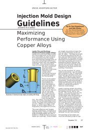
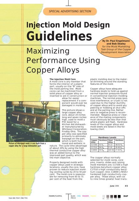
SPECIAL ADVERTISING SECTION<strong>Injection</strong> <strong>Mold</strong> <strong>Design</strong><strong>Guidelines</strong>MaximizingPerformance Using<strong>Copper</strong> AlloysBy Dr. Paul Engelmannand Bob Dealeyfor the <strong>Mold</strong> MarketingTask Group of the <strong>Copper</strong><strong>Development</strong> <strong>Association</strong>Picture of Whirlpool mold: A core built from acopper alloy for a large dishwasher partThe <strong>Injection</strong> <strong>Mold</strong> CoreA mold core is any member thatforms the interior of a plasticpart, usually on the "B" side ofthe mold parting line. <strong>Mold</strong>cores can be machined from asolid piece of copper alloy orinserted to aid in construction orallow for easierreplacement if a componentwould ever bedamaged in molding.This picture shows alarge copper alloycore, about 24 incheslong and seven incheshigh, used to mold aPVC bezel for aKitchen Aid dishwashermanufactured byWhirlpool Corporation,Findlay Ohio. The copperalloy was specifiedprimarily to eliminatewarpage on the part,which is both functionaland esthetic innature. The cycle time advantageof about 20% by using the highthermal conductive copper alloywas an added bonus to theimproved part quality, which wasthe main objective.Properly designed molds withcopper alloys used in strategiclocations, usually the core, haveproven to reduce injection moldingcooling cycles by 20 to 50 percent. The mold core is responsiblefor removing from 65 to 75per cent of the heat from theplastic molding due to the materialshrinking around the standingfeatures of the mold.<strong>Copper</strong> alloys have adequatehardness levels to hold up againstnormal injection pressures foundin conventional injection moldingmachines. The normal press (positiveinterference, or crush) is notused due to the higher ductilityof copper alloys and to avoid anypeening or hobbing at shut offsand at the parting line, Ratherzero to negative press is recommended.Negative press or clearanceof the mating componentsmust obviously be less than thatwhere plastic will flash. Hardnesslevels of the copper alloys andmold steels are listed in the followingchart:Hardness Levels<strong>Copper</strong> Hardness Steel HardnessAlloyAlloyC17200 41 R c H-13 38/52 R cC17510 96 R b P-20 28-48 R cC18000 94 R b 420 SS 27-50 R cThe copper alloys normallyselected for mold cores, corepins, inserts, slides and raisingmold members are; C17200 a highhardness beryllium-copper alloy;C17510 a high conductivity beryllium-copper;And, C18000 a NiSiCrhardened high conductivity copperalloy. These alloys, with sixto nine times greater heat trans-June 1999 45Issue date, Folio #, Date, TimeMODERN PLASTICS,BLACK CYAN MAGENTA YELLOWPMS ID 5% 25% 50% 75% 95%RHP
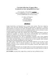
SPECIAL ADVERTISING SECTIONIllustration A: Heeled core with bubblerIllustration B: Inserted core with waterchannelsIllustration C: Self sealing core insertllustration D: Heeled core with water passages46 June 1999fer rates than steels (see<strong>Injection</strong> <strong>Mold</strong> <strong>Design</strong><strong>Guidelines</strong>, number 1 fordetails) have proven overtime to be the best choicesfor plastic forming moldcomponents. Other copperalloys, including the aluminumbronzes, haveattributes consistent withspecific applications in themold not associated withplastic forming. Theseinclude frictional wear andguiding surfaces wheretheir excellent frictionalproperties can best be utilized.Types of Core Construction<strong>Mold</strong> cores can bemachined from a solidmold "B" plate but aremore commonly insertedinto the "B" plate for easeof manufacture. Wheninserting the core, it is normallyretained with a heelor cap screws. The heel ona core, see Illustration A,typically extending .125 forsmall cores and .250 forlarger cores should have alength ratio of one to twotimes the heel for maximumstrength. The correspondingcounter bore ismachined into the plate withclearance around the perimeter,allowing the main core body toalign the insert. The depth ofthe heel pocket should matchthe insert to plus .0002 to insurethat the core does not move inthe molding cycle.Other means of holding the coreinclude blind pocketing,Illustration B, or self-sealing,Illustration C. The self-sealinginsert is a popular choice fordeep pocket inserting in applicationswhere most of the part,outer molding surfaces, areformed on the "B" side of themold. As the portion of thepocketed insert aligns the insert,the depth must be great enoughto withstand any side pressuresimposed in molding.Tensile StrengthTensile strength is extremelyimportant attribute when selectinga suitable mold material. Ifthere were a scale that measuredtoughness we would want to usethat for a mold material. The copperalloys exhibit a good combinationof tensile strength andductility, making them tough andideal candidates for mold components,not withstanding the highthermal conductivity properties.Tensile strength of the three copperalloys and three commonmold steels are compared in thefollowing tensile strength table.Tensile Strength (ksi)<strong>Copper</strong> ksi Steel ksiAlloyAlloyC17200 190 H-13 206C17510 110 P-20 146C18000 100 420 SS 125-250<strong>Mold</strong> CoolingThe injection molding cycle ismade up of a number of elements.They include the fillingportion, sometimes referred toas fill, pack and hold, the coolingportion and the mold openportion. The cooling portion isalways the longest and frequentlyrepresents greater than65 per cent of the overall cycle.Therefore, the longest elementin the overall cycle is where thegreatest benefit can beobtained in improving the injectionmolding cycle and wherecopper alloys work to your bestadvantage.The principles of heat flow in aninjection mold are: 1. Heat flowsfrom the body with the highertemperature to a body of lowertemperature (from the plastic tothe mold component the plasticis in contact with). 2. The temperaturedifference, not theamount of heat contained, determinesflow of heat. 3. Thegreater the difference in temperaturesbetween the plastic andthe mold component, thegreater the flow of heat. 4.Radiation, conduction and/orconvection transfer heat.Conduction is the main methodof heat transfer in an injectionmold.The amount of heat that must beconducted from a mold can becalculated. It must be rememberedthat 65 to 75 percent ofthis heat must be removedthrough the core of the mold.The formula is as follows:LHPMODERN PLASTICS, Issue date, Folio #, Date, TimeVersion #/Filename:BLACK CYAN MAGENTA YELLOWPMS ID 5% 25% 50% 75% 95%
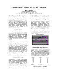
SPECIAL ADVERTISING SECTIONH= KAT (t p -t c )LWhere: H = Quantity of heat in BtuconductedK = Thermal conductivityfactor of mold material inBtu/hr/ft2/°F/A = Surface area of mold incontact in square feetT = Time in hourst p = Temperature of plastict c = Temperature ofcoolantL = Distance from surfaceof mold to coolant channel(Note: H-13, P-20 and 420 SS thermalconductivity ranges from 12 to 20, the threecommonly use copper alloys range from61 to 135)The importance that the highthermal conductivity of propertiesof copper alloys has in removingheat from the mold can be determinedfrom the formula.Obviously, the other elements ofthe formula are important considerationsthat must also be takeninto account when designing anefficiently cooled injection mold.However, changing the moldmaterial and the resultant thermalconductivity factor is normally thesimplest and most effective meansof achieving the best cycle time.Coolant OptionsThe injection mold core is one ofthe more difficult areas to placeand install t proper coolant channelsdue to the limited space availableand ejection options necessaryfor part removal. It is importantthat the coolant system beone of the first considerationsmade in mold design, as the overallsuccess of the mold project isdependant on how efficient themold cooling cycle can be made.The use of copper alloys and theirinherent superior thermal conductivityis the best guarantee themold has at success.<strong>Copper</strong> alloys will insure that thesurface temperate is as even aspossible and will extract heat awayfrom the plastic part. To maintainbest operating conditions andshort cooling cycles, it is imperativethat the heat is efficientlyremoved form the molds core.Coolant lines, in the form ofthrough-drilled channels or withthe use of bubblers or baffles,should be installed in the moldcore similar to a steel core. Thiswill provide the best results andyield the most efficient cooling.Should the same coolant diametersand placement not be possible,the copper alloys are moreforgiving than mold materialswith lower thermal conductivity.Typically the copper alloys willallow greater liberties in placementof coolant channels, whilecooling more efficiently thantheir steel counterparts. Cautionshould be used to insure thatadequate provisions have beenmade for removal of the heatfrom any mold component.If drilled coolant channels aremachined directly into the moldcore, the edge of the coolantchannel should be about twotimes the diameter away fromthe molding surface. The distancebetween the coolant channelsshould be from three to fivetimes the diameter, seeIllustration D. Positioning thecoolant channel any closer to themolding surface does not necessarilyresult in better cooling andin some cases provides a gradientdifferential in surface temperature,which could leave residualstresses in the plastic part. Moredetails on cooling options will bepresented in the sixth article inthis series.Cycle Time ImprovementsExtensive testing was conductedat Western Michigan Universitycomparing the use of the threemost commonly utilized copperalloys in injection molds C17200(A), C17510 (B) and C18000 (C)against H-13 and 420 SS. A singlecavity test mold for a 50-mmpolypropylene closure wasobtained and optimized to run atthe lowest cycle time possible.Identical mold components werefabricated from the three copperalloys and steel materials.Identical processing conditionswere established and each corematerial was tested with the onlyvariable being cooling time. GraphA illustrates the cycle advantagesand the reduction in cooling timesmade by the copper alloys whencompared directly to the conventionalmold steels.Each test was conducted after acontrolled stabilization period.For purposes of evaluating theresults of cycle time, cooling timewas the only variable. The onlyGraph A: Actual comparisons of best achievable cycleand cooling times in the same mold, the only changewas the core material.Graph B: Amount of part warpage Icompared to cycletime for copper alloys Vs tool steel.mold change was the core itself.The only processing changeallowed was to cooling time. Melttemperature, cooling temperatures,injection time, gate seal andother processing conditions weremonitored to insure identical conditions.This test was perhaps thefirst time ever that exacting comparisonswere made, under productiontype conditions, thatphysically demonstrated theadvantages of the superior thermalconductivity and effects onthe injection molding coolingcycle and the resultant overallmolding cycle.Graph B compares part warpage,in millimeters, between the threecopper alloys and two steel materialsat various cycle times. Thecopper alloys remove heat so efficientlythat part warpage is minimal,even at shorter cycle times.The benefit of improving partquality at faster molding cyclesover steel is obvious. However,the greatest advantage might bethe better consistency impartedinto the plastic parts as a result ofeven mold surface temperatures.This test was conclusive, confirminganecdotal experience fromJune 1999 47MODERN PLASTICS, Issue date, Folio #, Date, TimeVersion #BLACK CYAN MAGENTA YELLOWPMS ID 5% 25% 50% 75% 95%RHP
SPECIAL ADVERTISING SECTIONIllustration E: Chill plate applicationIllustration F: Self-sealing core with draftothers where cooling cycle timeimprovements of 20 to 50 percent are common on productionmolds when copper alloys areproperly utilized.Chill Plate ApplicationsFrequently molds with smalldiameter cores, those too smallfor cooling lines, benefit by seatingcopper alloy core pin headson a copper chill plate of thesame alloy. When ever core sizeor design allows you shouldinstall coolant lines using baffles,bubblers or drilled channels, tooptimize mold cooling and temperaturecontrol. When eitherthe number of core pins or thediameter prevents the installationof the coolant channels, thechill plate concept should beconsidered. Testing has foundthat the best results areobtained when the core pins andchill plate have the same highthermal conductivity numbers.Obviously the higher the thermalconductivity number the better.Coolant channels are installeddirectly into the chill plate toremove the heat and maintainthe proper mold core temperature.In small diameter cores,where size limitations preventwater channel is the core, thisconcept has been shown to bealmost as effective as cores withsmall coolant channels. The chillplate concept is not as effectiveas direct water cooling andshould not be used for largerdiameter cores where directcoolant is possible. Illustration Eshows a chill plate application.Note, the chill plate can beinstalled under the main core orwhen using sleeve ejection,mounted to the back of the ejectorhousing.Draft ConsiderationsThe molded plastic part must beejected from the core. Toenhance part ejection draft,tapering of the part feature toassist in mold release is necessary.The draft angle specifiedshould result after consultationwith the plastic material supplier,plastic part designer, molderand mold designer. Draft shouldbe as generous as possible andnormally matches the draft onthe cavity side to insure an evenand consistent wall thickness,see Illustration FRibs on the other hand present adifferent problem. Large draftangles results in thick wall sectionswhere the rib joins themain wall section. Normally, thejunction of the rib to the wallshould be one-half to two thirdsof the mating wall thickness. Theuse copper alloys is of greatbenefit in these situations. Therapid removal of heat from thethicker ribs, due to the moreefficient cooling of the copperalloys, will normally e reduce oreliminate the sink mark, which istypically caused by the delayedsolidification of plastic at thejunction of ribs at the wall of thepart. Without the benefit of thesuperior cooling of the copperalloy, injection pressure and holdtimes are often extended. Thisnot only results in longer cycletimes but also increases the incidenceof flash, warpage and overpacking of the molded part. ❐AcknowledgementsThe injection mold design guidelines werewritten by Dr. Paul Engelmann, AssociateProfessor, Western Michigan University andBob Dealey, Dealey's <strong>Mold</strong> Engineering, withthe support of Dr. Dale Peters, for the <strong>Mold</strong>Marketing Task Group of the <strong>Copper</strong><strong>Development</strong> <strong>Association</strong>. Kurt Hayden,graduate research assistant, WMU, generatedthe Illustrations. Research conducted byWMU plastic program students.DisclaimerThese guidelines are a result of research atWMU and industry experience gained withthe use of copper alloys in injection molding.While the information contained isdeemed reliable, due to the wide variety ofplastics materials, mold designs and possiblemolding applications available, no warrantiesare expressed or implied in theapplication of these guidelines.Contact InformationInformation on copper alloys is availablefrom the <strong>Copper</strong> <strong>Development</strong> <strong>Association</strong>,1-800-232-3282.For more information about the use of copper alloys in tooling, please write in 668 on the reader service card.48 June 1999LHPdate, Folio #, Date, TimeMODERN PLASTICS, IssueBLACK CYAN MAGENTA YELLOWPMS ID 5% 25% 50% 75% 95%