Single-Point Multi Range Air Velocity Transmitter - Sontay
Single-Point Multi Range Air Velocity Transmitter - Sontay
Single-Point Multi Range Air Velocity Transmitter - Sontay
- No tags were found...

You also want an ePaper? Increase the reach of your titles
YUMPU automatically turns print PDFs into web optimized ePapers that Google loves.
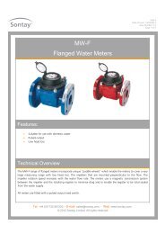
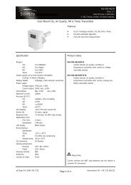
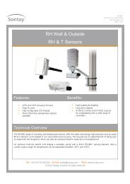
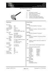
AV-DSPDate of Issue: 11/10/2012Issue Number: 5.6Page 1 of 5<strong>Single</strong>-<strong>Point</strong> <strong>Multi</strong> <strong>Range</strong><strong>Air</strong> <strong>Velocity</strong> <strong>Transmitter</strong>Features:Benefits:User selectable output signal, 0-10Vdc or4-20mAUser selectable measurement rangesDurabile and resistant to chemicalreagentsAdjustable probe depth using theoptional DPABuilt-in self-test featureIP65 housingTechnical OverviewThe AV-DSP is a single point, multi-range air velocity transmitter with user selectable 0-10Vdc or 4-20mAoutputs and 4 user selectable measurement ranges. The unit has a built-in self-test feature and the user canmanually override the output to 0%, 50% or 100% of output range to aid commissioning.A flange plate (DPA) is available for adjustment of the penetration depth.Tel: +44 (0) 1732 861200. - E-mail: sales@sontay.com. - Web: www.sontay.com.© 2012 <strong>Sontay</strong> Limited. All rights reserved
AV-DSPDate of Issue: 11/10/2012Issue Number: 5.6Page 2 of 5Specification:Output ranges:0 to 4 m/s (0 to 787 ft/min)0 to 8 m/s (0 to 1575 ft/min)0 to 16 m/s (0 to 3150f t/min)0 to 32 m/s (0 to 6299 ft/minAccuracy (±3% of range)0 to 4 m/s ±0.12 m/s (24 ft/min)0 to 8 m/s ±0.24 m/s (47 ft/min)0 to 16 m/s ±0.48 m/s (94 ft/min)0 to 32 m/s ±0.96 m/s (189 ft/min)Outputs:4-20mA, 100Ω loop resistance min.0-10Vdc into 4.7kΩ minSupply (current output):20Vdc to 35Vdc for 500Ω loop resistance12Vdc to 30Vdc for 100Ω loop resistanceSupply (Voltage output):17Vdc to 34Vdc14Vac to 26Vac supply into 4.7kΩ min.Max. current50mASpeed of response 3 seconds for 90% changeAmbient temp range -10 to +50°C (14 to 122°F)Housing:Material Flame retardant ABSDimensions 55mm x 90mm dia.(2.17 x 3.54”)Probe:Material DelrinDimensions 215mm x 19mm dia.(8.46 x 0.75”)ProtectionIP65Country of origin DenmarkPart Codes:AV-DSP<strong>Single</strong> point multi-range air velocity transmitterAccessoryDPADuct probe adjustment flangeThe products referred to in this data sheet meet therequirements of EU Directive 2004/108/ECTel: +44 (0) 1732 861200. - E-mail: sales@sontay.com. - Web: www.sontay.com.© 2012 <strong>Sontay</strong> Limited. All rights reserved
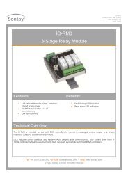
AV-DSPDate of Issue: 11/10/2012Issue Number: 5.6Page 3 of 5Installation:<strong>Transmitter</strong>s should only be fitted to a system after airflow calibration has been carried out and preferablyfollowing full fan running of at least several days, in order that the main contaminants have been removed fromthe stagnant system.1. Select a location in the duct where dust & contaminants are at a minimum.2. Drill a 19mm (0.75”) diameter hole and align the hole in the probe so it points into the air flow. Drill two holes at85mm (3.35”) centres and fix the IP65 housing to the duct with appropriate screws. The housing is designed tomake it easy for an electric screwdriver to be used if desired.3. Remove the front cover by twisting the lid and separating from the main body.4. Feed the cable through the waterproof gland and terminate the cores at the terminal block. Leaving some slackinside the unit, tighten the cable gland onto the cable to ensure water tightness.5. Replace the lid after the electrical connections have been made.6. Ensure that the supply voltage is within the specified tolerances.7. It is recommended that screened cable be used and that the screen should be earthed at the controller. Care shouldbe taken not to lay control signal wiring in close proximity to power or other cables which may produce significantelectromagnetic noise.8. Allow 3 minutes before checking functionality.9. Allow 30 minutes before carrying out pre-commissioning checks.The AV-DSP should be installed not less than 2 metres downstream from any heating or cooling devices, source ofmoisture such as humidifier, fan or bend in the ductwork.To ensure accurate readings the AV-DSP should be installed so that the element is 0.24 x the duct radius into theduct.0.24rRadiusDuctSensorTel: +44 (0) 1732 861200. - E-mail: sales@sontay.com. - Web: www.sontay.com.© 2012 <strong>Sontay</strong> Limited. All rights reserved
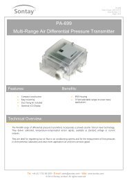
AV-DSPDate of Issue: 11/10/2012Issue Number: 5.6Page 4 of 5Installation (continued):Reading errors of up to 30% may be experienced if the elements are positioned in the centre of the duct.The AV-DSP should be mounted with the holes in the end of the probe orientated directly into the air flow, to allowfull air flow over the sensing element.The AV-DSP requires approx. 50mA. Ensure the supply to the sensor is capable of providing this current.If using a current output mode, the sensor must only be used with a 24Vdc supply. The sensor may be damaged ifsupplied with AC.Note: When using current output mode they are NOT loop powered and will require a common 0V connection.Connections & Jumper Settings:Output rangedip switch1 2 3 4ON DIP1:0-4m/s2:0-8m/s3:0-16m/s4:0-32m/sI ↔ U+24Vac/dc0VOutputLED0%out50%out100%outManual overridebuttonPUSH TOTEST OUTPUTSCurrent outputIf using a current output mode, the sensor must only beused with a 24Vdc supply. The sensor may be damagedif supplied with AC.Note: When using current output mode they are NOTloop powered and will require a common 0V connection.Output Signal Jumper Settings4-20mA (I)0-10Vdc (U)PlugSensorNB Standard units are factory set for an 0-10Vdc output.Output signal jumperOutput <strong>Range</strong> Selection:1 2 3 4ON DIPExample: 0-4m/s (0-787ft/min), the “raised” sectionof the dip switch is pushed towards the ON position(indicated by the white square).Dip switchOutput range 1 2 3 40 to 4m/s (787ft/min) ON OFF OFF OFF0 to 8m/s (1575ft/min) OFF ON OFF OFF0 to 16m/s (3150ft/min) OFF OFF ON OFF0 to 32m/s (6299ft/min) OFF OFF OFF ONTel: +44 (0) 1732 861200. - E-mail: sales@sontay.com. - Web: www.sontay.com.© 2012 <strong>Sontay</strong> Limited. All rights reserved
AV-DSPDate of Issue: 11/10/2012Issue Number: 5.6Page 5 of 5Self-Test & Manual Override ModeThe output of the AV-DSP can be manually overridden to one of 3 values by pressing the PCB mounted button. When thisbutton is pressed once, the output will change to 0% of the output’s range, when pressed again the output will change to50% of the output’s range and when pressed a third time will change the outputs to 100% of the outputs range. Pressingagain will return the outputs to automatic control.Example:First Press – <strong>Velocity</strong> output falls to 0%, LED flashes slowlySecond Press – <strong>Velocity</strong> output rises to 50%, LED flashes slowlyThird Press – <strong>Velocity</strong> output rises to 100%, LED flashes slowlyFourth Press – <strong>Velocity</strong> output reverts to automatic levels. The LED should be permanently on.Failure Mode:If the sensor element assembly is damaged, the output will change to the following fixed default value and the LED will flashrapidly;<strong>Velocity</strong> = 0%Whilst every effort has been made to ensure the accuracy of this specification, <strong>Sontay</strong> cannot accept responsibility for damage, injury,loss or expense from errors or omissions. In the interest of technical improvement, this specification may be altered without notice.Tel: +44 (0) 1732 861200. - E-mail: sales@sontay.com. - Web: www.sontay.com.© 2012 <strong>Sontay</strong> Limited. All rights reserved