UVOD - MIV
UVOD - MIV
UVOD - MIV

Create successful ePaper yourself
Turn your PDF publications into a flip-book with our unique Google optimized e-Paper software.
7(+1,ý.,89-(7,,63258.(=$7/$ý1(&,-(9,,)$=21(2'12'8/$512*/,-(9$=$3/,1292'(,VODOVODE PREMA EN-u 5451. 32'58ý-(=$.2-(1250$95,-(',2YD QRUPD RGUHÿXMH ]DKWMHYH ]D PDWHULMDOH PMHUHQMD L GR]YROMHQD RGVWXSDQMD PHKDQLþNH NDUDNWHULVWLNH L VWDQGDUdneprevlake cijevi i fazona od nodularnog lijeva.1RUPDYULMHGL]DFLMHYLID]RQHLSULERUNRMLVHSURL]YRGHSRVWXSNRPOLMHYDQMDSRåHOMLLOLRGSRMHGLQDþQLKOLMHYDQLKGLMHORYDNDRL]DRGJRYDUDMXüHVSRMHYH]DQD]LYQHSURPMHUH'1GR]DNOMXþQR'1.Norma vrijedi za cijevi, fazone i pribor, koji- LPDMXNROþDNHSULUXEQLFHLOLXWLþQHNUDMHYHVUD]OLþLWLPYUVWDPDEUWYLODNRMDQLVXVDVWDYQLGLRRYHQRUPH- VHRELþQRLVSRUXþXMXVXQXWDUQMRPLYDQMVNRP]DãWLWRP- VHSULPMHQMXMX]DWUDQVSRUWWHNXüLKPHGLMDQDWHPSHUDWXUDPDRGƒ&GRƒ&YDQSRGUXþMDVPU]DYDQMD2. 7(+1,ý.,=$+7-(9,2.1. SASTAV POVRŠINE I POBOLJŠANJACijevi, fazone i pribor moraju biti bez grešaka i površinski potpune.Ukoliko je potrebno, cijevi i fazone se smiju popravljati zavarivanjem da sH RWNORQH SRYUãLQVNH JUHãNH L PMHVWLPLþQLQHGRVWDFL NRML QH ]DKYDüDMX FLMHOX GHEOMLQX VWLMHQNH SRG XYMHWRP GD VH SRSUDYFL RGYLMDMX X VNODGX V SRVWXSFLPD SLVPHQRGHILQLUDQLP VXVWDYRP RVLJXUDQMD NYDOLWHWH SURL]YRÿDþD WH GD SRSUDYOMHQH FLMHYL L ID]RQH LVSXnjavaju sve zahtjeve kojepropisuje ova norma.02.2. VRSTE SPOJEVA2.2.1. Spojevi s prirubnicomMjere i tolerancije prirubnica na cijevima i fazonama moraju odgovarati mjerama prema EN 1092-2, a brtve za prirubnicemjerama prema ISO 7483.2.2.2. Pokretljivi spojevi9DQMVNLSURPMHULLWROHUDQFLMHXWLþQLKNUDMHYDFLMHYLLID]RQDVSRNUHWOMLYLPVSRMHPRSLVDQLVXXSRJODYOMX2.3. MATERIJALI U DODIRU S PITKOM VODOMUkoliko se cijevi, fazone i spojevi od nodularnog lijeva koriste u uvjetima za koje su namijenjeni, te ukoliko se nalaze utrajnom ili privremenom kontaktu s pitkom vodom namijenjenoj ljudskoj upotrebi, isti ne smiju promijeniti kvalitetu vode u tojmjeri da kod krajnjeg korisnika više ne odgovara zahtjevima EG-LOLRGJRYDUDMXüLK()7$-naputaka.2.4. MJERNI ZAHTJEVI2.4.1. Debljina stijenkeNazivna debljina stijenke eRGQRGXODUQRJOLMHYDUDþXQDVHRYLVQRRQD]LYQRPSURPMHUXDN, prema formuli, s minimumomod 6 mm za cijevi i 7 mm za fazone:e=K(0,5+0,001 DN),gdje jeK –IDNWRU]DRGUHÿLYDQMHNODVHGHEOMLQHVWLjenke. Odabire se iz reda cijelih brojeva: 8, 9, 10, 11, 12...Tolerancije nazivne debljine stijenke cijevi i fazona moraju biti prema tabeli1.Tabela 1Vrste lijevanih komada e, mm Tolerancija *, mmcentrifugirane cijevi6,0 -1,3>6,0 -(1,3+0,001 DN)Cijevi i fazone od7,0 -2,3necentrifugalnog lijeva >7,0 -(2,3+0,001 DN)* Navedene su samo negativne tolerancije, da se osiguradovoljan otpor unutarnjem tlaku.2.4.2. Vanjski promjerZa DN ” PRUD YDQMVNL SURPMHU FLMHYQRJ RWYRUD PMHUHQ FLUNRPHWURP ELWL WDNDY GD VH QD GXåLQL RG QDMPDQMH GYLMHWUHüLQHFLMHYLPMHUHQRRGXWLþQRJNUDMDPRåHL]YHVWLVSRM=D'1!YULMHGLSUHPDGRJRYRUXSURL]YRÿDþDLQDUXþLWHOMDLVWRXNROLNRVHFLMHYLPRUDMXVNUDüLYDWLQDJUDGLOLãWX2VLPWRJDPRUDLRYDOLWHWQDXWLþQLPNUDMHYLPDFLMHYLLID]RQD- ostati unutar tolerancije prikazanih u tabeli na strani 18- QHVPLMHSULMHüL]D'1GR'1RGQRVQR]D'1!METALSKA INDUSTRIJA VARAÆDIN d.d. Fabijanska 33, 42 000 Varaždin, Croatia H R V A T S K A42000 VARAÆDIN, Fabijanska 33 • Telefon: +385+42 404-100 Telefon: +385 • Fax: 42 404-100, +42 242-004 290-100 • E-mail: prodaja@miv.hr, prodaja-miv@vz.htnet.hrsales@miv.hr01/2005 0.1
1RUPLUDQHGXåLQHID]RQD'RSXãWHQDRGVWXSDQMDRGQRUPLUDQLKGXåLQDID]RQDSULND]DQDVXXWDEHOLTabela 2Vrsta fazone DN Odstupanje, mm0.RPDGVSULUXEQLFRPLNROþDNRPSpojni komad s prirubnicom6SRMQLNRPDGVNROþDNRPRedukcioni komad40 do 12001400 do 2000±25±3540 do 1200+ 50/ - 25Odcjepni komadi1400 do 2000+ 75/ - 35/XþQLNRPDGƒó 40 do 2000 ±(15+0,03 DN)/XþQLNRPDGƒé 40 do 2000 ±(10+0,025 DN)40 do 1200±(10+0,02 DN)/XþQLNRPDGƒLƒ1400 do 2000±(10+0,025 DN)7ROHUDQFLMHGXåLQD7ROHUDQFLMHGXåLQDQDYHGHQHVXXWDEHOLTabela 3Vrsta komadaTolerancijamm&LMHYLVNROþDNRP ± 30Fazone za spajanje s NROþDNRP ± 20Cijevi i fazone za spajanje s± 10*prirubnicama*Manje tolerancije su dogoYRURPL]PHÿXSURL]YRÿDþDLQDUXþLWHOMDPRJXüHDOLQHPDQMHRG“PP]D'1”L“PP]D'1!2.5. .$5$.7(5,67,ý1(95,-('1267,0$7(5,-$/$2.5.1. .DUDNWHULVWLNHþYUVWRüH&LMHYLID]RQHLSULERURGQRGXODUQRJOLMHYDPRUDMXLPDWLYULMHGQRVWLþYUVWRüHNDNRMHQavedeno u tabeli 4.Tabela 4Vrsta komada1DMQLåDYODþQDþYUVWRüD5 mMPa1DMQLåDLVWH]OMLYRVW$%DN 40 do DN 2000 DN 40 do DN 1000 DN 1100 do DN 2000Centrifugalno lijevane cijevi 420 10 7Necentrifugalno lijevane cijevi,fazone i pribor420 5 5NapoPHQD'RJRYRURPL]PHÿXSURL]YRÿDþDLQDUXþLWHOMDPRåHVHRGUHGLWLJUDQLFDWHþHQMD5 p0,2 . Ona ne smije biti manja od 270 Mpa,ako je A•]D'1GR'1LOL$•]D'1!WH03DXGUXJLPVOXþDMHYLPD8WRNXSURL]YRGQMHSURL]YRÿDþPRUDSURYRGiti prikladne testove :- SRSULQFLSXVOXþDMQRJX]RUNDVHRGVOXþDMQRRGDEUDQRJID]RQVNRJNRPDGDL]UDÿXMXSUREQHHSUXYHWHLLVSLWXMX- kontrolni sistem putem nerazornih ispitivanja, koji mora biti poduprt testom rastezanja.7YUGRüD7YUGRüDSR%ULQHOOXQHVPLMHSUHNRUDþLWL+%]DID]RQHLSULERU3ULVDVWDYQLPHOHPHQWLPDNRMLVXPHÿXVREQR]DYDUHQLMHQDSRGUXþMLPDL]ORåHQLPWRSOLQVNLPXWMHFDMLPDGR]YROMHQDYHüDWYUGRüDSR%ULQHOO-u.2.6. PREVLAKE I OBLOGE ZA FAZONE I PRIBOR2SüHQLWRPrevlake- FLQþDQa prevlaka s pokrovnim premazom- SROLHWLOHQIROLMDGRGDWDNELWXPHQSUHPD]XLOLFLQþDQRMSUHYODFLVSRNURYQLPSUHPD]RP- epoxy- zaštitni ovojiMETALSKA INDUSTRIJA VARAÆDIN d.d. Fabijanska 33, 42 000 Varaždin, Croatia H R V A T S K A42000 VARAÆDIN, Fabijanska 33 • Telefon: +385+42 Telefon: 404-100 +385 • Fax: 42 404-100, +42 242-004 290-100 • E-mail: prodaja@miv.hr, prodaja-miv@vz.htnet.hrsales@miv.hr0.2 01/2005
3. TESTIRANJAKvaliteta cijevi i fazona te njihove dimenzije ispituju se vizuelno, mjerenjima, te uzimanjem probnih uzoraka.=DLVSLWLYDQMHUDVWH]DQMHPNRULVWHVHX]RUFLþLMHVXGLPHQ]LMHQDYHGHQHXWDEHOLTabela 60Vrsta lijevanog elementaCentrifugalno lijevane cijevi s debljinom stijenke e umm:- e < 6- 6 ”H- 8 ”H- e •Necentrifugalno lijevane cijevi , fazone i pribor:- nalijevani uzorci- odvojeno lijevani uzorci:- debljina uzorka 12,5 mm za debljinu odljevka manjuod 12 mm- debljina uzorka 25 mm za debljinu odlijevka 12 mm ivišeIspitni uzorakPostupak ANazivnipromjermm2,53,55,06,05,06,012,0 ili14,0PresjeknazivnepovršineS 0, mm5,010,020,030,020,030,0-Ispitni uzorakPostupak BNazivnipromjermm2,523,575,056,185,056,18-Tolerancijapromjeramm±0,01±0,02±0,02±0,03±0,02±0,03-4. ISPITIVANJE NEPROPUSNOSTICijevni spojevi se ispituju na nepropusnost prema pozitivnom i negativnom unutarnjem tlaku, pozitivnom vanjskom tlaku,WHGLQDPLþNRPXQXWDUQMHPWODNXQD]DWRSURSLVDQLPXUHÿDMLPDLXSURSLVDQRPYUHPHQVNRPWUDMDQMX5. OSIGURANJE KVALITETE3URL]YRÿDþPRUDGRND]DWLGDVXQMHJRYLSURL]YRGLXVNODGXVRYRPQRUPRPSXWHPREDYOMDQMDWLSVNLKIXQNFLMVNLKLVSLWLYDQMDi nadziranja procesa proizvodnje.,VSLWLYDQMDPRUDSURYHVWLVDPSURL]YRÿDþLOLSUL]QDWLLQVWLWXW]DSURYRÿHQMHLVSLWLYDQMDXLPHSURL]YRÿDþD3URL]YRÿDþPRUDpotpune izvještaje pohraniti.3URL]YRÿDþ PRUD QDG]LUDWL NYDOLWHWX VYRMLK SURL]YRGD SXWHP VXVWDYD QDG]LUDQMD NDNR EL LVSXQLR WHKQLþNH ]DKWMHYH RYHnorme.6WRJD PRUD VXVWDY RVLJXUDQMD NYDOLWHWH SURL]YRÿDþD ELWL X VNODGX V ]DKWMHYLPD (1 6XVWDY RVLJXUDQMD NYDOLWHWHSURL]YRÿDþDPRUDELWLSURYHGHQRGVWUDQHXUHGD]DFHUWLILNDFLMXNRMLMHVDVYRMHVWUDQHDNUHGLWLUan u skladu s EN 45012.METALSKA INDUSTRIJA VARAÆDIN d.d. Fabijanska 33, 42 000 Varaždin, Croatia H R V A T S K A42000 VARAÆDIN, Fabijanska 33 • Telefon: +385+42 Telefon: 404-100 +385 • Fax: 42 404-100, +42 242-004 290-100 • E-mail: prodaja@miv.hr, prodaja-miv@vz.htnet.hrsales@miv.hr0.4 01/2005
TEHNISCHE LIEFERBEDINGUNEN FÜR DRUCKROHRE UND FORMSTÜCKE AUS DUKTILEM GUSSEISENFÜR GAS- UND WASSERLEITUNGEN NACH EN 5451. ANWENDUNGSBEREICHDiese Norm legt die Anforderungen an die Werkstoffe, die Abmessungen und zulässigen Abweichungen, diemechanischen Eigenschaften und die Standardüberzüge duktiler Gussrohre und Formstücke fest.Diese Norm gilt für Rohre, Formstücke und Zubehörteile, die nach einem beliebigen Giessverfahren oder aus gegossenenEinzelteilen hergestellt werden, ebenso wie für die entsprechenden Verbindungen für den Nennweitenbereich von DN 40 biseinschliesslich DN 2000.Diese Norm gilt für Rohre, Formstücke und Zubehörteile, die– mit Muffen, Flanschen oder Einsteckenden zur Verbindung mit unterschiedlichen Arten von Dichtungen versehen sind,die nicht Bestandteil dieser Norm sind;– üblicherweise mit einem Innen- und Aussenschutz geliefert werden;– zum Transport flüssiger Medien zwischen 0°C und 50°C geeignet sind, jedoch ausserhalb des Frostbereiches.02. TEHNISCHE ANFORDERUNGEN2.1. OBERFLÄCHENBESCHAFFENHEIT UND AUSBESSERUNGENRohre, Formstücke und Zubehörteile müssen frei von Fehler und Oberflächenungänzen sein. Wenn erforderlich, dürfenRohre und Formstücke z. B. durch Schweissen ausgebessert werden, um Oberflächenungänzen und örtliche Fehlstellen, dienicht die ganze Wanddicke betreffen, zu beseitigen, unter der Voraussetzung, dass die Ausbesserungen gemäss einer imQualitätssicherungssystem des Herstellers schriftlich festgelegten Verfahrensweise erfolgen und die ausgebesserten Rohreund Formstücke alle Anforderungen dieser Norm erfüllen.2.2. VERBINDUNGSARTEN2.2.1. FlanschverbindungenDie Masse und Toleranzen der Flansche von Rohren und Formstücken müssen mit prEN 1092-2 übereinstimmen und dieFlanschdichtungen mit ISO 7483.2.2.2. Bewegliche VerbindungenRohre und Formstücke mit beweglichen Verbindungen müssen bezüglich ihrer Aussendurchmesser DE und derenToleranzen im Bereich der Einsteckenden mit 2.4.2. übereinstimmen.2.3. STOFFE IN KONTAKT MIT TRINKWASSERWenn sie unter den Bedingungen eingesetzt werden, für die sie ausgelegt sind, dürfen duktile Gussrohre, Formstücke undderen Verbindungen, wenn sie in dauerndem oder zeitweiligem Kontakt mit Wasser, das für den menschlichen Gebrauchbestimmt ist, stehen, die Güte dieses Wassers nicht soweit verändern, dass sie beim Endverbraucher mit den Anforderungender EG-Richtlinien oder der endsprechenden EFTA-Richtlinien nicht mehr übereinstimmen.2.4. MASSANFORDERUNGEN2.4.1. WanddickeDie Nenngusswanddicke der Rohre und Formstücke muss in Abhängigkeit von der Nennweite nach der folgenden Formelerrechnet werden, mit einem Minimum von 6 mm für Rohre und 7 mm für Formstücke:e=K(0,5+0,001 DN)Dabei ist:K ein Faktor zur Bestimmung der Wanddickenklasse. Er ist aus einer Reihe ganzer Zahlen ausgewählt: ...8, 9, 10, 11, 12...Die Toleranzen für Nennwanddicken der Rohre und Formstücke müssen wie in Tabelle 1 angegeben sein.Tabelle 1Art des Gussstückes e, mm Toleranz *, mmSchleudergussrohre6,0 -1,3>6,0 -(1,3+0,001 DN)Nichtgeschleuderte7,0 -2,3Rohre und Formstücke >7,0 -(2,3+0,001 DN)* Es ist nur eine Minustoleranz angegeben, um einengenügenden Widerstand gegen Innendruck sicherzustellen.2.4.2. AussendurchmesserFür DN ” 300 muss der Aussendurchmesser des Rohrschaftes, gemessen mittels Circometer, so sein, dass übermindestens zwei Drittel der Rohrlänge, gemessen von Einsteckende, eine Verbindung hergestellt werden kann.Für DN > 300 gilt nach Vereinbarung zwischen Hersteller und Besteller das gleiche, wenn sie an der Baustelle gekürztwerden müssen.METALSKA INDUSTRIJA VARAÆDIN d.d. Fabijanska 33, 42 000 Varaždin, Croatia H R V A T S K A42000 VARAÆDIN, Fabijanska 33 • Telefon: +385+42 404-100 Telefon: +385 • Fax: 42 404-100, +42 242-004 290-100 • E-mail: prodaja@miv.hr, prodaja-miv@vz.htnet.hrsales@miv.hr01/2005 0.5
In addition, the ovality of the spigot end of pipes and fittings shall:- remain within the tolerance on page 18 for DN 40 to DN 200- not exceed 1% for DN 250 to DN 600 or 2% for DN > 600.02.4.3. Standardized lengths of fittingsThe permissible deviations on the standardized length shall be as given in table 2.Table 2Type of fitting DN Deviation, mmFlanged socketsFlanged spigotsCollarsTapers40 do 12001400 do 2000±25±3540 do 1200+ 50/ - 25Tees1400 do 2000+ 75/ - 35Bends 90° (¼) 40 do 2000 ±(15+0,03 DN)Bends 45° (é 40 do 2000 ±(10+0,025 DN)40 do 1200±(10+0,02 DN)Bends 22°30' and 11°15'1400 do 2000±(10+0,025 DN)2.4.4. Tolerances on lengthsThe tolerances on lengths shall be as given in table 3.Table 3Type of castingTolerancemmSocket and spigot pipes ± 30Fittings for socketed joints ± 20Pipes and fittings for flanged± 10*joints* By agreement between manufacturer and purchaser, smallertolerances are possible, but not less than ±3mm for DN”DQG±4mm for DN>600.2.5. MATERIAL CHARACTERISTICS2.5.1. Tensile propertiesPipes, fittings and accessories of ductile iron shall have the tensile properties given in table 4.Table 4Type of castingMinimum tensile strengthR mMPaMinimum elongation after fracture, A%DN 40 to DN 2000 DN 40 to DN 1000 DN 1100 to DN 2000Pipes centrifugally cast 420 10 7Pipes not centrifugally cast,fittings and accessories420 5 5Note. By agreement between manufacturer and purchaser, the R p0,2 .may be measured. It shall be not less than 270 Mpa when A•for DN 40 to DN 1000 or A•IRU'1!DQG03DLQRWKHUFDVHVDuring the manufacturing process the manufacturer shall carry out suitable test:- either a batch sampling system, where test bars shall be mashined from these samples and tensile tested- a system of process control by non-destructive testing, that shall be supported by tensile testing accordance.2.5.2. HardnessThe Brinell hardness shall not exceed 230 HB for pipes and 250 HB for fittings and accessories. For componentsmanufactured by welding, a higher Brinell hardness is allowed in the heat affected zone of the weld.METALSKA INDUSTRIJA VARAÆDIN d.d. Fabijanska 33, 42 000 Varaždin, Croatia H R V A T S K A42000 VARAÆDIN, Fabijanska 33 • Telefon: +385+42 Telefon: 404-100 +385 • Fax: 42 404-100, +42 242-004 290-100 • E-mail: prodaja@miv.hr, prodaja-miv@vz.htnet.hrsales@miv.hr0.6 01/2005
2.6. ÜBERZÜGE UND AUSKLEIDUNGEN FÜR FORMSTÜCKE UND ZUBEHÖRTEILE2.6.1. AllgemeinesÜberzüge:– Zinküberzug– Polyethylen-Folie (zusätzlich zum Bitumenanstrich oder zum Zinküberzug mit Deckbeschichtung)– Epoxy– SchutzbindenAuskleidungen:– Polyurethan– Epoxy– dickere Zementmörtelauskleidung– Zementmörtelauskleidung mit seal coatDiese Überzüge und Auskleidungen müssen mit den entsprehenden EN-Normen übereinstimmen oder, wo keine EN-Normen existieren, müssen sie mit ISO-Normen oder mit nationalen Normen oder mit einer vereinbarten technischenLieferbedingung übereinstimmen.Die Nennschichtdicke der Zementmörtelauskleidung und ihre Tolleranz müssen so sein wie in Tabelle 5 angegeben.Tabelle 50DNNennwertSchichtdicke, mmToleranz*Maximale Rissbreite undmaximaler radialer Versatz40 bis 300 3,5 -1,5 0,8350 bis 600 5 -2 1,0700 bis 1200 6 -2,5 1,21400 bis 2000 9 -3 1,5*Es ist nur eine Minustoleranz gegeben.Anmerkung: Rohrenden können eine Abschrägung von maximal 50 mm Länge haben.2.6.2. BeschichtungenDas Beschichtungsmaterial muss aus einem bituminösen Stoff oder aus Kunstharz bestehen; geeignete Zusätze (wieLösungsmittel, anorganische Füllstoffe usw.) sind erlaubt, um ein leichtes Aufbringen und Trocknen zu erreichnen.Von dem Aufbringen der Beschichtung muss die Gussoberfläche trocken, frei von Rost oder losen Teilchen sowie von Öloder Fett sein.Die Beschichtung muss werksseitig durch Tauchen, Spritzen oder Bürsten aufgebracht werden.Die Beschichtung muss die gesamte Oberfläche des Gussstückes gleichmässig bedecken und muss ein glattes undhomogenes Erscheinungsbild zeigen. Sie muss ausreichend trocken sein, um sicherzustellen, dass die beschichteten Teilenicht aneinanderkleben.Wenn die Schichtdicke gemessen wird (direkt am Gussstück mit z. B. magnetisch oder mit einemNassschichtdikkenmessgerät, oder indirekt auf einem Probenträger mit z. B. Mikrometer oder nach einem Wägeverfahren),darf die mittlere Schichtdicke nicht weniger als 70m und die örtliche Mindestschichtdicke nicht weniger als 50m betragen.2.7. KENNZEICHNUNG DER ROHRE UND FORMSTÜCKEAlle Rohre und Formstücke müssen leserlich und dauerhaft gekennzeichnet sein und mindestens die folgendenInformation tragen:– Kennzeichen des Herstellers– Kennzeichen des Herstelljahres– Kennzeichen für duktiles Gusseisen– die DN– Nenndruck PN bei Flanschen, wenn zutreffend– Hinweis auf diese Norm– Kennzeichen der Zertifizierungsstelle, wenn zutreffend– Wanddickenklasse der Schleudergussrohre, wenn abweichend von K9.Die ersten fünf Informationen müssen eingegossen oder eingeschlagen sein.2.8. DICHTHEIT2.8.1. Rohre und FormstückeRohre und Formstücke müssen so ausgelegt sein, dass sie bei ihrem zulässigen Bauprüfdruck (PEA) wasserdicht sindund dürfen keine sichtbare Undichtheit, kein Schwitzen oder irgendein anderes Anzeichen für ein Versagen zeigen.METALSKA INDUSTRIJA VARAÆDIN d.d. Fabijanska 33, 42 000 Varaždin, Croatia H R V A T S K A42000 VARAÆDIN, Fabijanska 33 • Telefon: +385+42 404-100 Telefon: +385 • Fax: 42 404-100, +42 242-004 290-100 • E-mail: prodaja@miv.hr, prodaja-miv@vz.htnet.hrsales@miv.hr01/2005 0.7
02.8.2. VerbindungenVerbindungen müssen:– ohne Undichtheit dauerhaft dem höchsten zulässigen Bauteilbetriebsdruck (PMA) der entsprechenden Rohre undFormstücke oder ihrem eigenen PMA, wie in den Herstellerkatalogen angegeben, widerstehen, welcher auch immerder niedrigste ist– dicht bei negativem Innendruck, der unter Druckstoss-Bedingungen auftreten kann– ohne Wassereintritt einem hydrostatischen Aussendruck von 2 bar widerstehen, wenn sie für einen Einsatz tiefer als 5m unter Wasserspiegel vorgesehen sind (z. B. Fluss, See, Grundwasser)Alle Verbindungen müssen so ausgelegt sein, dass sie voll abwinkelbar sind; folglich darf die vom Hersteller anzugebendezulässige Abwinkelbarkeit nicht geringer sein als– 3° 30' für DN 40 bis DN 300– 2° 30' für DN 350 bis DN 600– 1° 30' für DN 700 bis DN 2000.Alle Verbindungen müssen so ausgelegt sein, dass sie eine ausreichend grosse Längsbeweglichkeit besitzen; diezulässige Längsverschiebung muss vom Hersteller genannt werden.3. PRÜFVERFAHRENQualität und Masse der Rohre und der Formstücke müssen visuell prüfen und gemessen werden und auch muss maneine Probestabes entnommen werden.Die Dicke der Probe und der Durchmesser des Probestabes für den Zugversuch müssen wie in Tabelle 6 angegeben sein.Tabelle 6Art der GussstückProbestabVerfahren ANenndurchmessermmNennquerschnittsflächeS 0, mmProbestabVerfahren BNenndurchmessermmDurchmessertoleranzmmSchleudergussrohre mit Wanddicken in mm:- e < 6- 6 ”H- 8 ”H- e •2,53,55,06,05,010,020,030,02,523,575,056,18±0,01±0,02±0,02±0,03Nichtgeschleuderte Rohre, Formstücke und Zubehörteile:- angegossene Proben- getrennt gegossene Proben- Probendicke 12,5 mm für Gussstückdicke kleiner12 mm- Probendicke 12,5 mm für Gussstückdicke 12 mm undgrösser5,06,012,0 ili14,020,030,0-5,056,18-±0,02±0,03-4. DICHTHEITSPRÜFUNGDie Dichtheit der Verbindungen müssen gegen positiven und negativen Innendruck, positiven Aussendruck unddynamischen Innendruck geprüft werden und es muss mit dieser Norm nachweisen sein.5. QUALITÄTSSICHERUNGDer Hersteller muss die Übereinstimmung seiner Erzeugnisse mit dieser Norm nachweisen durch Ausführen vonFunktions-Typprüfungen und Überwachendes Fertigungsprozesses.Typprüfungen müssen entweder vom Hersteller selbst oder von einem anerkannten Prüfinstitut in seinem Namendurchgeführt werden.Die vollständigen Berichte dieser Typprüfungen müssen vom Hersteller für den Nachweis der Konformität aufbewahrtwerden.Der Hersteller muss die Qualität seiner Produkte während der Fertigung durch ein Fertigungsüberwachungssystemüberwachen, um die technischen Anforderungen dieser Norm zu erfüllen.Folglich muss das Qualitätssicherungssystem des Herstellers mit den Anforderungen der EN 29002 übereinstimmen. DasQalitätssicherungssystem des Herstellers sollte von einer Zertifizierungsstelle, die ihrerseits in Übereinstimmung mit EN45012 akkreditiert ist, überprüft sein.METALSKA INDUSTRIJA VARAÆDIN d.d. Fabijanska 33, 42 000 Varaždin, Croatia H R V A T S K A42000 VARAÆDIN, Fabijanska 33 • Telefon: +385+42 Telefon: 404-100 +385 • Fax: 42 404-100, +42 242-004 290-100 • E-mail: prodaja@miv.hr, prodaja-miv@vz.htnet.hrsales@miv.hr0.8 01/2005
ENGINEERING TERMS OF DELIVERY FOR PRESSURE PIPES AND FITTINGS OF DUCTILE CAST IRONFOR GAS AND WATER PIPE LINES ACCORDING TO EN 5451. SCOPEThis standard specifies requirements for materials, dimensions and tolerances, mechanical properties and standardcoatings of ductile iron pipes and fittings.This standard covers pipes, fittings and accessories cast by any type of foundry process or manufactured by fabrication ofcast components, as well as corresponding joints, in a size range extending from DN 40 to DN 2000, inclusive.This standard applies to pipes, fittings and accesories which are:- manufactured with socketed, flanged or spigot ends for jointing by means of various types of gaskets which are notwithin the scope of this standard;- normally delivered externally and internally coated;- suitable for fluid temperatures between 0°C and 50°C, excluding frost.2. TECHNICAL REQUIREMENTS2.1. SURFACE CONDITION AND REPAIRSPipes, fittings and accessories shall be free from defects and surface imperfections.When necessary, pipes and fittings may be repaired, for example by welding, in order to remove surface imperfectionsand localized defects which do not affect the entire wall thickness, provided that the repairs are carried out according to awritten procedure included in the manufacturer's quality assurance system, and the repaired pipes and fittings comply with allthe requirements of this standard.02.2. TYPES OF JOINTS2.2.1. Flanged jointsThe dimension and tolerances of the flanges of pipes and fittings shall comply with prEN 1092-2 and flange gaskets withISO 7483.2.2.2. Flexibile jointsPipes and fitting with flexibile joints shall comply with 2.4.2. for their spigot external diameters DE and their tolerances.2.3. MATERIALS IN CONTACT WITH POTABLE WATERWhen used under the conditions for which they are designed, in permanent or in temporary contact with water intended forhuman consumption, ductile iron pipes, fittings and their joints shall not change the quality of that water to such an extent thatit fails to comply with the requirements of EU and EFTA regulations at the end user.2.4. DIMENSIONAL REQUIREMENTS2.4.1. Wall thicknessThe nominal iron wall thickness of pipes and fittings shall be calculated as a function of the nominal size, DN by thefollowing formula, with a minimum of 6 mm for pipes and 7 mm for fittings:e=K(0,5 + 0,001 DN)where:K is a coefficient used for determination of thicknes class. It is selected from a series of whole numbers: ...8, 9, 10, 11, 12...The tolerances on nominal wall thickness of pipes and fittings shall be given in table 1.Table 1Type of casting e, mm Tolerance *, mmPipes centrifugally cast6,0 -1,3>6,0 -(1,3+0,001 DN)Pipes not centrifugally 7,0 -2,3cast and fittings >7,0 -(2,3+0,001 DN)* A negative tolerance only is given, so as to ensure sufficientresistance to internal pressure.2.4.2. External diameterFor DN ”WKHH[WHUQDOGLDPHWHURIWKHSLSHEDUUHOPHDVXUHGZLWKDFLUFXPIHUHQWLDOWDSHVKDOOEHVXFKDVWRDOORZWKHassembly of the joint over at least two thirds of the pipe length from the spigot end when the pipe needs to be cat on site.For DN > 300, the same applies to a percentage of the pipes, after agreement between manufacturer and purchaser.METALSKA INDUSTRIJA VARAÆDIN d.d. Fabijanska 33, 42 000 Varaždin, Croatia H R V A T S K A42000 VARAÆDIN, Fabijanska 33 • Telefon: +385+42 404-100 Telefon: +385 • Fax: 42 404-100, +42 242-004 290-100 • E-mail: prodaja@miv.hr, prodaja-miv@vz.htnet.hrsales@miv.hr01/2005 0.9
In addition, the ovality of the spigot end of pipes and fittings shall:- remain within the tolerance on page 18 for DN 40 to DN 200- not exceed 1% for DN 250 to DN 600 or 2% for DN > 600.02.4.3. Standardized lengths of fittingsThe permissible deviations on the standardized length shall be as given in table 2.Table 2Type of fitting DN Deviation, mmFlanged socketsFlanged spigotsCollarsTapers40 do 12001400 do 2000±25±3540 do 1200+ 50/ - 25Tees1400 do 2000+ 75/ - 35Bends 90° (¼) 40 do 2000 ±(15+0,03 DN)Bends 45° (é 40 do 2000 ±(10+0,025 DN)40 do 1200±(10+0,02 DN)Bends 22°30' and 11°15'1400 do 2000±(10+0,025 DN)2.4.4. Tolerances on lengthsThe tolerances on lengths shall be as given in table 3.Table 3Type of castingTolerancemmSocket and spigot pipes ± 30Fittings for socketed joints ± 20Pipes and fittings for flanged± 10*joints* By agreement between manufacturer and purchaser, smallertolerances are possible, but not less than ±3mm for DN”DQG±4mm for DN>600.2.5. MATERIAL CHARACTERISTICS2.5.1. Tensile propertiesPipes, fittings and accessories of ductile iron shall have the tensile properties given in table 4.Table 4Type of castingMinimum tensile strengthR mMPaMinimum elongation after fracture, A%DN 40 to DN 2000 DN 40 to DN 1000 DN 1100 to DN 2000Pipes centrifugally cast 420 10 7Pipes not centrifugally cast,fittings and accessories420 5 5Note. By agreement between manufacturer and purchaser, the R p0,2 .may be measured. It shall be not less than 270 Mpa when A•for DN 40 to DN 1000 or A•IRU'1!DQG03DLQRWKHUFDVHVDuring the manufacturing process the manufacturer shall carry out suitable test:- either a batch sampling system, where test bars shall be mashined from these samples and tensile tested- a system of process control by non-destructive testing, that shall be supported by tensile testing accordance.2.5.2. HardnessThe Brinell hardness shall not exceed 230 HB for pipes and 250 HB for fittings and accessories. For componentsmanufactured by welding, a higher Brinell hardness is allowed in the heat affected zone of the weld.METALSKA INDUSTRIJA VARAÆDIN d.d. Fabijanska 33, 42 000 Varaždin, Croatia H R V A T S K A42000 VARAÆDIN, Fabijanska 33 • Telefon: +385+42 Telefon: 404-100 +385 • Fax: 42 404-100, +42 242-004 290-100 • E-mail: prodaja@miv.hr, prodaja-miv@vz.htnet.hrsales@miv.hr0.10 01/2005
2.6. COATINGS FOR FITTINGS AND ACCESSORIES2.6.1. GeneralExternal coatings:- zinc coating with finishing layer- polyethylene sleeving (as a supplement to the bituminous paint or to the zinc coating with finishing layer)- epoxy- adhesive tapes.Internal coatings (linings):- polyurethane- epoxy- thicker cement mortar lining- cement mortar lining with seal coatThese external and internal coatings shall comply with the corresponding EN standards, or where no EN standard exist,they shall comply with ISO standards or with national standards, or with an agreed technical specification.The nominal thickness of the cement mortar lining and its tolerance shall be as given in table 5.Table 50DNNominal valueThickness, mmTolerance*Maximum crack width andradial displacement40 to 300 3,5 -1,5 0,8350 to 600 5 -2 1,0700 to 1200 6 -2,5 1,21400 to 2000 9 -3 1,5*A negative tolerance only is given.Note: Pipe ends may have a chamfer of maximum length 50 mm.2.6.2. Paint coatingsThe coating material shall be of a bitumen or synthetic resin base; appropriate additives (such as solvents, inorganicfillers,...) to allow easy application and drying are permitted.Prior to application of the coating, the casting surface shall be dry, free from rust or non adhering particles of foreignmatter such as oil or grease.The coating shall be works-applied by dipping, by spraying or by brush.The coating shall uniformly cover the whole surface of the casting and have a smooth regular appearance. Drying shall besufficient to ensure that it will not stick to adjacent coated pieces.When measured (directly on the casting by e.g. magnetic, or indirectly on a token by e.g. micrometer, or by a weightmethod), the mean thickness of the coating shall be not less than 70PDQGWKHORFDOPLQLPXPWKLFNQHVVVKDOOEHQRWOHVVWKDQP2.7. MARKING OF PIPES AND FITTINGSAll pipes and fittings shall be legibly and durably marked and shall bear at least the following information:- the manufacturer's name or mark- the identification of the year of manufacture- the identification as ductile iron- the DN- the PN rating of flanges when applicable- the reference to this standard- the identification of third party certification when applicable- the class designation of centrifugally cast pipes when other than K9.The first five markings given above shall be cast-on or cold stamped.2.8. LEAKTIGHTNESS2.8.1. Pipes and fittingsPipes and fittings shall be designed to be watertight at their allowable test pressure, and shall exhibit no visible leakage,sweating or any other sign of failure.2.8.2. JointsJoints shall be designed:- to durably withstand without leakage the allowable maximum operating pressure (PMA) of corresponding pipes andfittings, or their own PMA as given in the manufacturer's catalogues, whichever is the lowestMETALSKA INDUSTRIJA VARAÆDIN d.d. Fabijanska 33, 42 000 Varaždin, Croatia H R V A T S K A42000 VARAÆDIN, Fabijanska 33 • Telefon: +385+42 404-100 Telefon: +385 • Fax: 42 404-100, +42 242-004 290-100 • E-mail: prodaja@miv.hr, prodaja-miv@vz.htnet.hrsales@miv.hr01/2005 0.11
0- to be leaktight under negative internal pressure, which may occur under surge conditions- to withstand without any ingress of water an external hydrostatic pressure of 2 bar, when they are intended for usedeeper than 5 m below the water levelAll joints shall be designed to be fully flexible; consequently, the allowable angular deflection declared by the manufacturershall be not less than:- 3°30' for DN 40 to DN 300- 2°30' for DN 350 to DN 600- 1°30' for DN 700 to DN 2000All joints shall be designed to provide sufficient axial movement; the allowable withdrawal shall be declared by themanufacturer.3. TEST METHODSThe quality and dimensions of pipes and fittings shall be visually inspected, measured and taken samples.The thickness of the sample and the diameter of the test bar shall be as given in table 6.Table 6Type of castingTest barmethod ANominaldiameterNominal areaTest barmethod BNominaldiameterTolerance ondiameterCentrifugally cast pipes with wall thickness e in mm:- e < 6- 6 ”H- 8 ”H- e •Pipes not centrifugally cast, fittings and accessories:- integrally cast samples- separately cast samples:- sample thickness 12,5 mm for casting thicknessless than 12 mm- sample thickness 25 mm for casting thickness 12mm and over4. WORKS LEAKTIGHTNESS TESTmm2,53,55,06,05,06,012,0 or14,0S 0, mmJoints shall be tested to positive and negative internal pressure, to positive external pressure and to dynamic internalpressure on test assamblies and time in accordance with this standard.5. QUALITY ASSURANCEThe manufacturer shall demonstrate the conformity of his products with this standard by carrying out performance typetests and controlling the manufacturing process.The type test shall be carried out either by the manufacturer or at his request by a competent testing institute in order todemonstrate compliance with the requirements of this standard. Full reports of these type tests shall be retained by themanufacturer as evidence of compliance.The manufacturer shall control the quality of his products during their manufacture by a system of process control in orderto comply with the technical requirements of this standard.Consequently, the manufacturer's quality assurance system shall comply with the requirements of EN 29002.The manufacturer's quality assurance system should be approved by a third party certification body who is accredited inaccordance with EN 45012.5,010,020,030,020,030,0-mm2,523,575,056,185,056,18-mm±0,01±0,02±0,02±0,03±0,02±0,03-METALSKA INDUSTRIJA VARAÆDIN d.d. Fabijanska 33, 42 000 Varaždin, Croatia H R V A T S K A42000 VARAÆDIN, Fabijanska 33 • Telefon: +385+42 Telefon: 404-100 +385 • Fax: 42 404-100, +42 242-004 290-100 • E-mail: prodaja@miv.hr, prodaja-miv@vz.htnet.hrsales@miv.hr0.12 01/2005
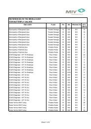
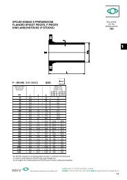
PRIRUBNICE IZ NODULARNOG LIJEVAFLANGES OF DUCTILE CAST IRONFLANSCHE AUS DUKTILEM GUSSEISEN0PN 10 – GGG EN 1092-2 (DIN 28604)Nazivni promjerNominal sizeNonnweiteDN d 1 D b k n d 2 d 3 h d 4 f kg40 56 150 19 110 4 19 73 39 83 3 1,750 66 165 19 125 4 19 83 40 98 3 2,160 77 175 19 135 4 19 94 40 108 3 2,365 82 185 19 145 4 19 99 41,5 118 3 2,580 98 200 19 160 8 19 115 43 133 3 2,9100 118 220 19 180 8 19 134 45 153 3 3,3125 144 250 19 210 8 19 160 47,5 183 3 4150 170 285 19 240 8 23 185 50 209 3 4,9200 222 340 20 295 8 23 237 55 264 3 6,8250 274 400 22 350 12 23 291 60 319 3 9,6300 326 455 24,5 400 12 23 346 65 367 4 13350 378 505 24,5 460 16 23 397 70 427 4 14400 429 565 24,5 515 16 28 447 75 477 4 16450 480 615 25,5 565 20 28 499 80 527 4 19500 532 670 26,5 620 20 28 551 85 582 4 23600 635 780 30 725 20 31 657 95 682 5 31700 738 895 32,5 840 24 31 755 105 797 5 40,5800 842 1015 35 950 24 34 860 115 904 5 55METALSKA INDUSTRIJA VARAÆDIN d.d. Fabijanska 33, 42 000 Varaždin, Croatia H R V A T S K A42000 VARAÆDIN, Fabijanska 33 • Telefon: +385+42 404-100 Telefon: +385 • Fax: 42 404-100, +42 242-004 290-100 • E-mail: prodaja@miv.hr, prodaja-miv@vz.htnet.hrsales@miv.hr01/2005 0.13
0PN 16 – GGG EN 1092-2 (DIN 28605)Nazivni promjerNominal sizeNonnweiteDN d 1 D b k n d 2 d 3 h d 4 f kg40 56 150 19 110 4 19 73 39 83 3 1,750 66 165 19 125 4 19 83 40 98 3 2,160 77 175 19 135 4 19 94 40 108 3 2,365 82 185 19 145 4 19 99 41,5 118 3 2,580 98 200 19 160 8 19 115 43 133 3 2,9100 118 220 19 180 8 19 134 45 153 3 3,3125 144 250 19 210 8 19 160 47,5 183 3 4150 170 285 19 240 8 23 185 50 209 3 4,9200 222 340 20 295 12 23 237 55 264 3 6,6250 274 400 22 355 12 28 291 60 319 3 9,2300 326 455 24,5 410 12 28 346 65 367 4 12350 378 520 26,5 470 16 28 400 70 432 4 17400 429 580 28 525 16 31 452 75 484 4 22450 480 640 30 585 20 31 505 80 544 4 28500 532 715 31,5 650 20 34 559 85 606 4 37600 635 840 36 770 20 37 666 95 721 5 57700 738 910 39,5 840 24 37 765 105 791 5 59800 842 1025 43 950 24 41 871 115 899 5 74PN 25 – GGG EN 1092-2 (DIN 28606)Nazivni promjerNominal sizeNonnweiteDN d 1 D b k n d 2 d 3 h d 4 f kg40 56 150 19 110 4 19 73 39 83 3 1,750 66 165 19 125 4 19 83 40 98 3 2,160 77 175 19 135 8 19 94 40 108 3 2,365 82 185 19 145 8 19 99 41,5 118 3 2,580 98 200 19 160 8 19 115 43 133 3 2,9100 118 235 19 190 8 23 134 45 159 3 3,8125 144 270 19 220 8 28 160 47,5 184 3 4,6150 170 300 20 250 8 28 187 50 214 3 5,9200 222 360 22 310 12 28 241 55 274 3 8,7250 274 425 24,5 370 12 31 295 60 331 3 13300 326 485 27,5 430 16 31 351 65 389 4 18350 378 555 30 490 16 34 412 70 446 4 25,5400 429 620 32 550 16 37 465 75 503 4 33450 480 670 34,5 600 20 37 518 80 553 4 39500 532 730 36,5 660 20 37 574 85 613 4 49600 635 845 42 770 20 41 684 95 718 5 71,5700 738 960 46,5 875 24 44 774 105 820 5 90800 842 1085 51 990 24 50 882 115 929 5 123METALSKA INDUSTRIJA VARAÆDIN d.d. Fabijanska 33, 42 000 Varaždin, Croatia H R V A T S K A42000 VARAÆDIN, Fabijanska 33 • Telefon: +385+42 Telefon: 404-100 +385 • Fax: 42 404-100, +42 242-004 290-100 • E-mail: prodaja@miv.hr, prodaja-miv@vz.htnet.hrsales@miv.hr0.14 01/2005
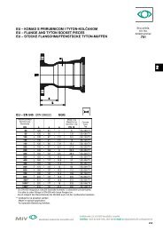
0PN 40 – GGG EN 1092-2 (DIN 28607)Nazivni promjerNominal sizeNonnweiteDN d 1 D b k n d 2 d 3 h d 4 f kg40 56 150 19 110 4 19 73 39 83 3 1,750 66 165 19 125 4 19 83 40 98 3 2,160 77 175 19 135 8 19 94 40 108 3 2,365 82 185 19 145 8 19 99 41,5 118 3 2,580 98 200 19 160 8 19 115 43 133 3 2,9100 118 235 19 190 8 23 134 45 159 3 3,8125 144 270 23,5 220 8 28 167 47,5 184 3 5,9150 170 300 26 250 8 28 196 50 214 3 8200 222 375 30 320 12 31 253 55 281 3 14250 274 450 34 385 12 34 310 60 343 3 23,5300 326 515 39,5 450 16 34 370 65 406 4 33,5PRIRUBNICE IZ NODULARNOG LIJEVAFLANGES OF DUCTILE CAST IRONFLANSCHE AUS DUKTILEM GUSSEISSENSLOBODNE PRIRUBNICE IZ NODULARNOG LIJEVALOOSE FLANGES OF DUCTILE CAST IRONLOSFLANSCHE AUS DUKTILEM GUSSEISSENDN 40 – 300: PN 10-16-25-40 DN 40 – 300: PN 10-16-25-40DN 40 – 800: PN 10-16-25 DN 40 – 600: PN 10-16-25METALSKA INDUSTRIJA VARAÆDIN d.d. Fabijanska 33, 42 000 Varaždin, Croatia H R V A T S K A42000 VARAÆDIN, Fabijanska 33 • Telefon: +385+42 404-100 Telefon: +385 • Fax: 42 404-100, +42 242-004 290-100 • E-mail: prodaja@miv.hr, prodaja-miv@vz.htnet.hrsales@miv.hr01/2005 0.15
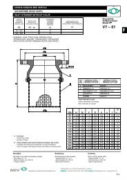
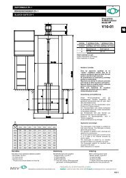
UNION SPOJ -.2/ý$&,=$)$=216.(.20$'(6$1$92-(0',1SCREW – ON SOCKRETS FOR FITTINGS DIN 28601STECKMUFFEN- VERBINDUNGEN DIN 286010.ROþDN6RFNHW0XIIHNazivnipromjerNominalSizeNennweiteDN d1 d2 d3 d4 d5 d6 t1 t2 t3 h1.ROþDN6RFNHW0XIIHkgza, for, fürCijevPipeRohreFazonskikomadiFittingsForm-Stücke40 56 84,2 61,4 77 77 67 74 28 15 1,7 1,4 1,380 98 127,2 103,4 120 120 109 84 30,5 16,5 10 3,4 2,8 2,4100 118 147,2 123,5 140 140 130 88 31,5 4,3 3,3 3,1125 144 176,8 149,6 167 167 156 91 17 5,7 4,5 4150 170 202,8 175,6 193 193 183 94 33 18 7,1 5,6 4,9200 222 257,8 227,8 248 248 235 100 19,5 13 10,3 8,0 7,1250 274 311,8 279,9 302 302 288 106 34 21 14,2 11,1 9,7300 326 365,8 332 356 356 340 110 36 22,5 18,6 14,3 12,5EUU1 prsten s navojemScrew RingSchraubring2 brtveni prsten prema DIN-u 28601Gasket according to DIN 28601Dichtung3 klizni prsten prema DIN-u 28601Sliding ring according to DIN 2860GleitringNROþDNVQDYRMHPScrewed SocketSchraubmuffeMETALSKA INDUSTRIJA VARAÆDIN d.d. Fabijanska 33, 42 000 Varaždin, Croatia H R V A T S K A42000 VARAÆDIN, Fabijanska 33 • Telefon: +385+42 Telefon: 404-100 +385 • Fax: 42 404-100, +42 242-004 290-100 • E-mail: prodaja@miv.hr, prodaja-miv@vz.htnet.hrsales@miv.hr0.16 01/2005
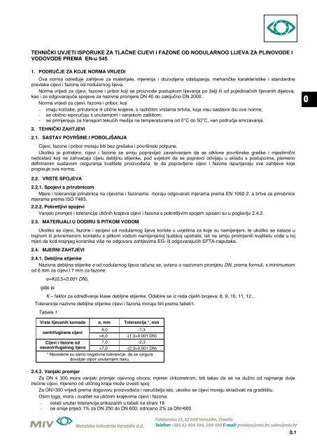
BRTVEGASKETSFLACHDICHTUNGEN0Nazivni promjerNominal sizeNonnweite D skg/100 komadakg/100 piecekg/100 StückDN d PN 10 PN 16 PN25 PN 40 PN10/PN16 PN25/PN40 PN 10 PN 16 PN25 PN 4040 49 92 3 3 250 62 107 3 4 460 72 117 3 4 4 565 77 127 3 4 4 580 89 142 3 4 4 7100 115 162 168 3 5 4 9125 141 192 194 3 5 4 12150 169 218 224 3 5 7 14200 220 273 284 290 3 6 8 20250 273 328 329 340 352 3 6 10 11 27300 324 378 384 400 417 3 6 12 13 48350 356 438 444 457 474 3 6 17 18 59400 407 489 495 514 546 3 7 19 21 70450 458 539 555 565 571 3 7 22 27 79500 508 594 617 624 628 3 7 25 33 80600 610 695 734 731 747 3 7 29 36 110700 712 810 804 833 - 3 8 41 38 190800 813 917 911 942 - 3 8 49 46 21083876792=$0217$ä87/$ý1,+&,-(9,I FAZONA S PRIRUBNICAMA1. %UWYHQLUXESULUXEQLFXLSORVQDWXEUWYXRþLVWLWLLSURYMHULWLGDOLVXXLVSUDYQRPVWDQMX1HXSRWUHEOMDYDWLRãWHüHQLPDWHULMDO2. $NRVHXJUDÿXMXQH]DãWLüHQLYLMFLWUHED– ako postoji opasnost od korozije – vijke zaštititi asfaltnom masom.3. Kod polaganja cijevi i fazona treba osigurati ispravno nalijeganje, a cijevni jarak savjesno zatrpati. Kruti cijevni spojevi ne mogu prihvatitiUD]OLþLWDRSWHUHüHQMD1LXNRPVOXþDMXQHVPLMXVHFLMHYLLID]RQHSRGJUDÿLYDWLNDPHQMHPLGUXJLPPDWHULMDOLPDYHüPRUDMXOHåDWLQDWOXXkojem nema kamenja. Ako je na dnu jarka stijena, mora se dno pokriti slojem pijeska, šljunka ili drobljenog kamena u debljini od najmanje15 cm.4. Za raspored provrta za vijke kod cijevi i fazona s prirubnicama vrijedi pravilo da vertikalna os prirubnice, koja stoji okomito na ravnini uNRMRMVHSRODåHFMHYRYRGQHVPLMHSUROD]LWLNUR]SURYUWH]DYLMNH5. Posebna napomena za ugradnju fazona s prirubnicama (osobito FFR komada):METALSKA INDUSTRIJA VARAÆDIN d.d. Fabijanska 33, 42 000 Varaždin, Croatia H R V A T S K A42000 VARAÆDIN, Fabijanska 33 • Telefon: +385+42 Telefon: 404-100 +385 • Fax: 42 404-100, +42 242-004 290-100 • E-mail: prodaja@miv.hr, prodaja-miv@vz.htnet.hrsales@miv.hr0.20 01/2005
da bi se izbjegle greške kod ugradnje, na prirubnici su postavljene oznake za ugradnju u obliku dva nasuprotna zareza. Kod ugradnjeove oznake treba poravnati po vertikali (visak) ili horizontali (libela).Zbog razlike u brojevima rupa za vijke kod ))5NRPDGD]DX]LPDWüHSULNOMXþQHDUPDWXUHLID]RQHNRVLSRORåDMXSURVWRUXXVOXþDMXSRJUHãQHXJUDGQMH2YDNYD]DNUHWDQMDL]UDåHQDXVWXSQMHYLPDPRJXüDVXRYLVQRRQD]LYQRPSURPMHUXGRºPrimjer: FFR 300/200 PN100Upozorenje!Stupnjevi zakretanja kod velikih nazivnih promjera jedva su primjetni.ASSEMBLY INSTRUCTIONS FOR PRESSUREPIPES AND FITTINGS WITH FLANGES1. Centering spigot, flange and gasket are to clear and test for their duly condition. Do not use damaged material!2. If unprotected bolts are used, the bolts and nuts have to be protected by asphalt mass, if corrosion danger exists.3. Flanged pipes and fittings have to be carefully bedded and the pipe ditch carefully back filled. Different loadings can not be supportedby riding pipe joints. Pipes and fittings must in no case be underpinned with stones or other material, they must rest on a stonelessground. Rocky ground must be covered with at least 15 cm thick layer of sand, gravel or crushed rock.4. To bolt hole lay-out for the flanged pipes and fittings follows a rule according to which the vertical flange axis perpendicular to the pip lineplane must not pass trough any bolt hole.5. Special note for installation of flanged fittings (especially FFR fittings):to avoid installation errors, the flanges receive installation markings in form of two opposed notches. Care should be taken that themarkings are vertically fathomed or horizontally aligned respectively.Because of different numbers of bolt holes in the flanges of the FFR fittings, the connected valves and fittings will be inclined to one sideif the installation is not correct. Depending on the nominal size, possible angle of twist may amount up to 22,5ºExample: FFR 300/200 PN 10Attention!The angles of twist for large nominal size are hardly noticeable.MONTAGELEITUNG FÜR DRUCKROHRE UNDFORMSTÜCKE MIT FLANSCHE1. Dichtleiste, Flansche und Flachdichtung säubern, auf ihren ordnungsgemäßen Zustand prüfen. Kein beschädigtes Material verwenden!2. Werden ungeschützte Schrauben eingebaut, so sind die Schrauben und Muttern mit Asphaltmasse zu schützen, sofern Korrosionsgefahrbesteht.3. Flanschrohre und –formstücke müssen sorgfältig verfüllt werden. Unterschiedliche Belastung können von den starren Rohrverbindungennicht abgefangen werden. Auf keine Fall dürfen die rohre und Formstücke mit Steinen und anderen Materialien unterbaut werden, siemüssen auf steinfreiem Boden liegen. Felsgrund ist mit einer mindestes 15 cm dicken Sand-, Kies oder Splittschicht abzudecken.4. Bei Flanschrohren und Flanschformstücken gilt für die Anordnung der Schraublöcher die Regel, dass in die zur Rohrleitungsebenesenkrecht stehende Flanschenachse keine Schraubenlöcher fallen.5. Besonders Anmerkung für den Einbau von Flanschfomrstück (besonders FFR – Stücke)Um Einbaufehler zu vermeiden, sind an den Flanschen Einbaumarkierungen in Form von zwei gegenüberliegende Kerben angebracht,Es ist darauf zu achten, dass die Markierungen beim Einbau senkrecht ausgelotet bzw. waagerecht ausgerichtet werden.Bedingt durch unterschiedliche Anzahl der Schraubenlöcher bei FFR – Stücken liegen bei falschem Einbau die Anschließenden Armaturenoder Formstücke schief im Raum. Mögliche Verdrehungsgrade (ja nach Nennweit)bis zu 22,5ºAchtung!Verdrehungsgrade bei großen Nennweit kaum wahrnehmbar.METALSKA INDUSTRIJA VARAÆDIN d.d. Fabijanska 33, 42 000 Varaždin, Croatia H R V A T S K A42000 VARAÆDIN, Fabijanska 33 • Telefon: +385+42 404-100 Telefon: +385 • Fax: 42 404-100, +42 242-004 290-100 • E-mail: prodaja@miv.hr, prodaja-miv@vz.htnet.hrsales@miv.hr01/2005 0.21
9$1-6.,3520-(5,7/$ý1,+&,-(9,OUTSIDE DIAMETERS OF PRESSURE PIPES52+5$8(1'85&+0(66(5)ÜR DRUCKROHRE'139&FLMHY39&SLSH39&5RKU3(FLMHY3(SLSH3(5RKUýHOLþQDFLMHY6WHHOSLSH6WDKOURKU1/FLMHY'&,SLSH***5RKU$&FLMHY$&SLSH$=5RKU(1',1',1NDOLEFDOLENDOLE(1(131(1 (1 ',1 ',1 (1 31 31 31 31 31 NDOLE QHNDOLE 31 31 7RO 6/FLMHY&,SLSH**5RKU““““METALSKA INDUSTRIJA VARAÆDIN d.d. Fabijanska 33, 42 000 Varaždin, Croatia H R V A T S K A42000 VARAÆDIN, Fabijanska 33 • Telefon: +385+42 Telefon: 404-100 +385 • Fax: 42 404-100, +42 242-004 290-100 • E-mail: prodaja@miv.hr, prodaja-miv@vz.htnet.hrsales@miv.hr0.22 01/2005
D – SP –'(0217$ä1(6/2%2'1(35,58%1,&(D – SP – LOOSE FLANGESD – SP – LOSFLANSCHES'1 WODN E ' I . J3131 31313131 31313131 31313131 31313131 313131 31 31 3131 31 31 3131 31 31 3131 31 31 31 3131 31 31 3131 31 31 31 31 31 31 31 31 31 31 31 31 31 31 31 31 31 Aıı A ııbBroj artikla:Art. No.Artikelnummer:0METALSKA INDUSTRIJA VARAÆDIN d.d. Fabijanska 33, 42 000 Varaždin, Croatia H R V A T S K A42000 VARAÆDIN, Fabijanska 33 • Telefon: +385+42 404-100 Telefon: +385 • Fax: 42 404-100, +42 242-004 290-100 • E-mail: prodaja@miv.hr, prodaja-miv@vz.htnet.hrsales@miv.hr01/2005 0.23