Response of juvenile scalloped hammerhead sharks to electric stimuli
Response of juvenile scalloped hammerhead sharks to electric stimuli
Response of juvenile scalloped hammerhead sharks to electric stimuli
- No tags were found...

Create successful ePaper yourself
Turn your PDF publications into a flip-book with our unique Google optimized e-Paper software.
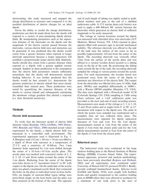
242ARTICLE IN PRESSS.M. Kajiura, T.P. Fitzgerald / Zoology 112 (2009) 241–250shortcoming, this study measured and mapped thecharge distribution in seawater and compared it <strong>to</strong> themodeled distribution <strong>of</strong> <strong>electric</strong> charges for an idealdipole.Given the ability <strong>to</strong> model the charge distribution,predictions can then be made about how the <strong>sharks</strong> willrespond <strong>to</strong> a variety <strong>of</strong> prey-simulating dipole <strong>electric</strong>fields. By manipulating parameters such as the separationdistance <strong>of</strong> the electrodes on the dipole and themagnitude <strong>of</strong> the <strong>electric</strong> current passed between theelectrodes, various <strong>electric</strong> field sizes and intensities canbe generated. It was predicted that the <strong>sharks</strong> wouldorient from a greater distance when exposed <strong>to</strong> largerelectrode separations because a larger separation willestablish a proportionally larger <strong>electric</strong> field. Similarly,<strong>sharks</strong> should also orient from a greater distance whenexposed <strong>to</strong> a dipole with a greater applied currentstrength. Implicit in these predictions is the assumptionthat the <strong>electric</strong> field parameters remain sufficientlynaturalistic that the <strong>sharks</strong> will demonstrate normalfeeding behavior. It was further predicted that the<strong>sharks</strong> would be best attuned (i.e. demonstrate thegreatest sensitivity) <strong>to</strong> <strong>electric</strong> <strong>stimuli</strong> that most closelyresembled their natural prey. These predictions weretested by quantifying the response distance <strong>of</strong> the<strong>sharks</strong> <strong>to</strong> various <strong>stimuli</strong> and subsequently calculatingthe minimum voltage gradient that elicited a response(i.e. their threshold sensitivity).MethodsElectric field measurementTo verify that the literature model <strong>of</strong> <strong>electric</strong> fieldintensity values (Kalmijn, 1982a; Griffiths, 1989; Denny,1993; Benedek and Villars, 2000) matched actual valuesexperienced by the <strong>sharks</strong>, a dipole <strong>electric</strong> field wasmeasured in a controlled tank environment. Theexperimental apparatus used is illustrated in Fig. 1.A fiberglass tank (122 cm 243 cm 76 cm) was filled <strong>to</strong>a depth <strong>of</strong> 48 cm with seawater at a temperature <strong>of</strong>27.5 1C and a resistivity <strong>of</strong> 18.0 O cm. Two 1 mmdiameter holes separated by 1 cm were drilled throughthe center <strong>of</strong> a 61.0 cm 41.9 cm acrylic plate. Theacrylic plate was marked with concentric circles <strong>of</strong> 2, 3,4, 5, 10, 15 and 20 cm radius around the center <strong>of</strong> the1 cm dipole. Radiating from the center <strong>of</strong> the dipolewere lines drawn at 151 increments from 01 <strong>to</strong> 901 withrespect <strong>to</strong> the dipole axis. On the underside <strong>of</strong> the acrylicplate was glued a machined acrylic block that connectedthe holes on the plate <strong>to</strong> individual screw-in hose barbs.Fifty cm lengths <strong>of</strong> seawater-filled tygon tubing werepress-fitted snugly on the hose barbs and the plate wasthen centered on the bot<strong>to</strong>m <strong>of</strong> the tank. The oppositeend <strong>of</strong> each length <strong>of</strong> tubing was tightly sealed <strong>to</strong> goldplatedstainless steel pins at the end <strong>of</strong> a shieldedunderwater cable. A 12 V marine deep cycle battery wasused <strong>to</strong> apply a 600–800 mA DC current between theelectrodes which generated an <strong>electric</strong> field <strong>of</strong> sufficientmagnitude <strong>to</strong> be easily measured.The voltage at various locations around the dipolewas measured with chlorided silver wire electrodes (10 TMedwire; Mount Vernon, NY, USA) encased in glasspipettes filled with seawater agar <strong>to</strong> provide mechanicalstability. The reference electrode was affixed <strong>to</strong> the side<strong>of</strong> the tank near the surface <strong>of</strong> the water as far aspossible (approximately 145 cm) from the center <strong>of</strong> thedipole. The recording electrode was vertically <strong>of</strong>fset5 mm from the surface <strong>of</strong> the acrylic plate and wasaffixed <strong>to</strong> a vertical wooden dowel secured <strong>to</strong> a slidingtrack on the lip <strong>of</strong> the tank. By positioning the slidingtrack around the lip <strong>of</strong> the tank, the recording electrodesampled the voltage at various points around the acrylicplate. For each measurement, the wooden dowel waspositioned away from the center <strong>of</strong> the dipole <strong>to</strong>minimize any dis<strong>to</strong>rtion <strong>of</strong> the <strong>electric</strong> field. The outputfrom the electrodes was filtered (low pass: 0.1 kHz, highpass: 300 Hz) and amplified differentially at 10000 with a Warner DP304 amplifier (Hamden, CT, USA).The data were digitized with a PowerLab model 16/30(Colorado Springs, CO, USA) sampling at 1 kHz usingChart s<strong>of</strong>tware and a 1 mV calibration pulse wasprovided at the start and end <strong>of</strong> each recording session.Measurements were made <strong>of</strong> the voltage at 2, 3, 4, 5, 10,15 and 20 cm radius and at angles from 01 <strong>to</strong> 901 at 151increments with respect <strong>to</strong> the dipole axis. The order inwhich the points were sampled was randomized and acomplete data set was collected three times. Themeasurements were repeated for dipole separationdistances <strong>of</strong> 3 cm and 5 cm. For the 3 cm dipole,measurements started at 3 cm from the center <strong>of</strong> thedipole (1.5 cm from the closest pole) and for the 5 cmdipole measurements started at 4 cm from the center <strong>of</strong>the dipole (1.5 cm from the closest pole).Behavioral assaysThe behavioral trials were conducted in the largeoutdoor holding pens at the Hawaii Institute <strong>of</strong> MarineBiology (HIMB), Coconut Island, Oahu. The experimentalapparatus, pro<strong>to</strong>col and analysis methodologyhave been previously described (Kajiura and Holland,2002) and all experiments were conducted underUniversity <strong>of</strong> Hawaii IACUC pro<strong>to</strong>col 99-028-3. Briefly,<strong>juvenile</strong> <strong>scalloped</strong> <strong>hammerhead</strong> <strong>sharks</strong>, Sphyrna lewini(Griffith and Smith, 1834), were caught with barblesshooks and quickly transported <strong>to</strong> the outdoor holdingpens at HIMB where they were allowed <strong>to</strong> acclimate fora minimum <strong>of</strong> one week prior <strong>to</strong> the start <strong>of</strong>