Beam Diagnostic Cameras - Lasertrack.ru
Beam Diagnostic Cameras - Lasertrack.ru
Beam Diagnostic Cameras - Lasertrack.ru

You also want an ePaper? Increase the reach of your titles
YUMPU automatically turns print PDFs into web optimized ePapers that Google loves.
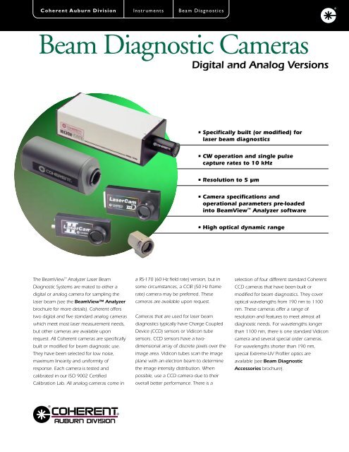
Coherent Auburn Division Inst<strong>ru</strong>ments <strong>Beam</strong> <strong>Diagnostic</strong>s<strong>Beam</strong> <strong>Diagnostic</strong> <strong>Cameras</strong>Digital and Analog Versions• Specifically built (or modified) forlaser beam diagnostics• CW operation and single pulsecapture rates to 10 kHz• Resolution to 5 lum• Camera specifications andoperational parameters pre-loadedinto <strong>Beam</strong>View Analyzer software• High optical dynamic rangeThe <strong>Beam</strong>View Analyzer Laser <strong>Beam</strong><strong>Diagnostic</strong> Systems are mated to either adigital or analog camera for sampling thelaser beam (see the <strong>Beam</strong>View Analyzerbrochure for more details). Coherent offerstwo digital and five standard analog cameraswhich meet most laser measurement needs,but other cameras are available uponrequest. All Coherent cameras are specificallybuilt or modified for beam diagnostic use.They have been selected for low noise,maximum linearity and uniformity ofresponse. Each camera is tested andcalibrated in our ISO 9002 CertifiedCalibration Lab. All analog cameras come ina RS-170 (60 Hz field rate) version, but insome circumstances, a CCIR (50 Hz framerate) camera may be preferred. Thesecameras are available upon request.<strong>Cameras</strong> that are used for laser beamdiagnostics typically have Charge CoupledDevice (CCD) sensors or Vidicon tubesensors. CCD sensors have a twodimensionalarray of discrete pixels over theimage area. Vidicon tubes scan the imageplane with an electron beam to determinethe image intensity distribution. Whenpossible, use a CCD camera due to theiroverall better performance. There is aselection of four different standard CoherentCCD cameras that have been built ormodified for beam diagnostics. They coveroptical wavelengths from 190 nm to 1100nm. These cameras offer a range ofresolution and features to meet almost alldiagnostic needs. For wavelengths longerthan 1100 nm, there is one standard Vidiconcamera and several special order cameras.For wavelengths shorter than 190 nm,special Extreme-UV Profiler optics areavailable (see <strong>Beam</strong> <strong>Diagnostic</strong>Accessories brochure).
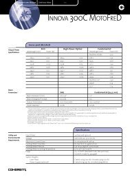
Coherent Auburn DivisionInst<strong>ru</strong>ments<strong>Beam</strong> <strong>Diagnostic</strong>s<strong>Beam</strong> <strong>Diagnostic</strong> <strong>Cameras</strong>All standard CCD cameras accept C-Mountoptics and accessories and are deliveredwithout a glass/plastic window in front of thesensor array. Such windows are liable todistort the optical beam. However, a LowDistortion Face Plate (LDFP) filter is suppliedwith each camera. The LDFP is a laser gradeND filter glass specified and polished fordiagnostics use. It is mounted in a C-Mountring and provides sufficient attenuation ofroom light so that the camera can be usedwith the lights on. For operation below400 nm, the LDFP must be removed.The selection and specification charts on theback page provide the information needed toselect an appropriate camera for your needs.To aid selection, consider the most importantfactors which determine the choice of acamera. These are the laser wavelength, thepower density or peak intensity, the laserbeam size to be viewed, the resolutionrequired, the laser operating cycle (CW orpulsed) and the camera cost. The followingpages will help guide these choices.<strong>Beam</strong> SizeThe beam size, or range of sizes, is one of thefirst factors to consider when selecting acamera. In order to image the entire beamproperly, the 1/e 2 beam diameter should beno more than 80% of the minimum activesensor dimension. Such a criterion usuallyprovides sufficient image area for sensing theimage periphery and allows space for beamwander during measurement or alignmentprocedures. However, for critical beammeasurement, such as D 4σ, the 1/e 2 diametershould not cover more than half of the sensorheight or width.The primary determinant of the minimumbeam diameter which can be adequatelymeasured is the spatial measurementaccuracy. Fewer sensor elements in the beamimage will result in less accuratemeasurements. For example, 40 pixels acrossthe beam image will provide the resolutionfor precision beam diameter measurements.Thus, the minimum beam sizes in theselection chart on the back page are basedFull Field ModeFirst Field Second Field Frame Integrationon this criterion. The smallest beam to bemeasured should cover at least 40 CCDsensor pixels (or their equivalent Vidiconprocessing elements).Aquisition Modesand Image ResolutionUnfortunately, it is not possible to immediatelyjudge a camera’s maximum effective imagearea and resolution from the total sensor areaand the pixel spacing, respectively. This isbecause the pixel information is electronicallyacquired in methods which in some modesdoes not access all the pixels in the array. WithInterline transfer cameras, such as theLaserCam II, all pixel information is acquiredevery cycle of the camera (1/30 s). Withframe integration cameras, only theinformation from alternating rows of pixels areacquired during one cycle (1/60 s), and theinformation from the other rows are acquiredon the next cycle. This is called interlacedoperation (see the figure above).It is sometimes desirable to work in full fieldand half field modes (with both interlinetransfer and frame integration cameras) to beable to acquire less pixels from the sensorarray, but process the information faster. Thiswas important with older and slowercomputers, but with faster modern computersit is possible to fully acquire all the sensorinformation, process it, and display a profileimage updating in real time (~10-25 Hz).+ =Figure of Interlaced OperationHalf Field ModeHowever, for the highest image acquisitionrate, the full field and half field modes arestill used. With full field operation, onlyalternate pixels on alternate lines are sampled.With half field operation, only every fourthpixel on every fourth line is sampled (see thefigure below). Such operation clearly speedsup information processing, but lowers theresolution. Thus, there are three commonimage resolution modes for camera basedbeam diagnostics: Frame (752 x 480),Full Field (376 x 240), and Half Field(188 x 120).Operation with Pulsed LasersExtra care must be expended when selectinga camera for use with pulsed rather than CWlasers. This is because there can beinteractions between the timing of the pulsesof the laser and the timing of the electronicacquisition of the optically-inducedinformation on the sensor pixels.The LaserCam II and LaserCam IIID camerascan capture pulsed beam images in framemode (every pixel) up to a maximum pulserate of 30 Hz. The frame integration camerascan only capture pulsed beam images in fullfield and half field modes up to a maximumpulse rate of 60 Hz.If the camera is to be used for analysis ofsingle pulses at greater than 60 Hz repetitionrate, then a camera with an electronic shutteris recommended. The speed of the shutter isthen the determining factor in the rep ratethat can be sampled. By adjusting the shutterto a shorter interval than the time betweenpulses, single pulses can be sampled. Forinstance; a 1 ms shutter time can be used tosample a single pulse in a 1 kHz or less reprate laser pulse train.
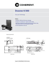
Note that for 900-1100 nm wavelengths, the1/4" LaserCam II and LaserCam IIID camerasare limited when used with CW lasersbecause of image ghosting.Highlighted Analog Camera FeaturesOptical Dynamic RangeAll analog video cameras have a very limitedoptical dynamic range (typically 200:1 to300:1) when operated as sensors forquantitative measurement of opticalradiation. Digital cameras have a much largeroptical dynamic range (over 1200:1) due tolower noise achieved by the integraldigitizing electronics located in the cameraitself. The optical dynamic range is the ratio ofthe maximum to the minimum optical signallevels that can be incident on the sensor toachieve a linear response. The maximumlinear response typically occurs at ~80% ofthe photosaturation level and the minimumresponse corresponds to the illumination levelat which the signal can be distinguished fromthe background noise.<strong>Beam</strong> AttenuationOptical attenuators are used to reduce thelaser intensity to match the camera responserange. The optics must be laser gradesubstrate, properly specified and polished sothat the beam is not distorted by theintroduction of the attenuation. We offerattenuation optics designed to thesespecifications and packaged for use with ourcameras. Typical attenuations are 1:1 to400,000:1, but even larger attenuations arepossible. Suggested configurations deliveringup to a 25 billion to 1 ratio of laser gradeoptical attenuation are illustrated in the <strong>Beam</strong><strong>Diagnostic</strong> Accessories brochure.LaserCam IIC-48C-64E-7290LaserCam II 1/2" CCD(33-3120 for 120 VAC and 33-3138 for 240 VAC)Excellent camera for beams up to 4 mm in the 190-1100 nm wavelength range. This is aninterline transfer camera that will allow frame mode (all pixels) to be used for pulsed beams in theentire 190-1100 nm range. This is accomplished through a custom CCD mask that eliminatesghosting from pulsed beams in the 900-1100 nm range.LaserCam II 1/4" CCD(33-2965 for 120 VAC and 33-2973 for 240 VAC)Preferred camera for small beams in the 190-1100 nm wavelength range. This is an interlinetransfer camera that will allow frame mode (all pixels) to be used for pulsed beams up to 900 nm.C-48 Camera 2/3" CCD(33- 3153 for 120 VAC, 33-6701 for 240 VAC)Large CCD array camera for 190-1100 nm operation with the widest dynamic range and excellentoverall performance. The C-48 Camera has the large-area sensor and electronics integrated in asingle traditional package, but there is no shutter. This camera is very popular.C-64 1/2" Camera CCD(33-3162 for 120 VAC, 33-6720 for 240 VAC)Excellent camera for 190-1000 nm operation with good resolution and dynamic range. Wherespace is a problem, camera has a small sensor head and simple shutter. The C-64 camera consistsof a remote sensor package and a table top control unit.E-7290 Camera(33-3260 for 120 VAC, 33-3765 for 240 VAC)The camera of choice for operation in the infrared between 1100 and 1800 nm. Note that the E-7290 vidicon camera operates at a maximum of 1 Hz for pulses. For operation at higher pulserates and in the infrared beyond 1100 nm, consult your local Coherent sales office.For further specifications, see the Comparison and Selection of <strong>Cameras</strong> on the back page, or call your localCoherent representative.For 10-355 nm OperationThe spectral range of cameras can be extended to wavelengths shorter than whatthe camera alone can respond to by converting the wavelength with an imageplate system that does not distort the beam and is designed for use with camerasand lasers. The Extreme UV <strong>Beam</strong> Profiler Optic will allow imaging of a beam in thewavelength range of 10-355 nm. (See the <strong>Beam</strong> <strong>Diagnostic</strong> Accessories brochurefor more details.)
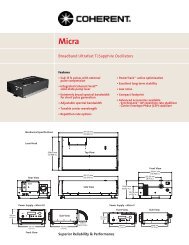
<strong>Beam</strong> <strong>Diagnostic</strong> <strong>Cameras</strong>Digital and Analog Camera Selection ChartFor a more detailed description of cameras, see the <strong>Beam</strong> <strong>Diagnostic</strong> <strong>Cameras</strong> brochure.Camera Name LaserCam LaserCam LaserCam II LaserCam II C-48 C-64 E-7290IIID 1/2" IIID 1/4" 1/2" 1/4"Format*** Digital Digital Analog Analog 2/3" Analog 1/2" Analog AnalogInterline Interline RS-170 RS-170 RS-170 RS-170 RS-170Transfer TransferCCD CCD Interline Interline Frame Frame VidiconTransfer Transfer Integration Integration736(H) x 736(H) x CCD CCD CCD CCD484(V) 484(V)Wavelength Range 190-1100 nm 190-1100 nm* 190-1100 nm 190-1100 nm* 190-1100 nm 190-1000 nm 400-1800 nm(400-2200 nmOptional)Maximum Active Horz. Vert. Horz. Vert. Horz. Vert. Horz. Vert. Horz. Vert. Horz. Vert. Horz. Vert.Sensor Area (mm) 6.4 4.8 3.6 2.7 6.4 4.8 3.6 2.7 8.8 6.6 6.4 4.8 12.5 9.4Digitized Resolution:Frame Mode (µm) 8.5 9.8 4.8 5.5 8.4 9.8 4.8 5.6 11.5 13.5 8.5 9.8 17.3 19.5Full Field Mode (µm) 17 19.6 9.6 11 16.8 19.2 9.6 11.3 23 27 17 19.6 34.6 39Half Field Mode (µm) 34.1 39.3 19.2 22 33.6 39.2 19.2 22.6 46 54 34 39.2 69.2 78Minimum <strong>Beam</strong> 0.34 0.40 0.19 0.22 0.34 0.40 0.19 0.22 0.46 0.54 0.34 0.40 0.69 0.78Size (mm)Dynamic Range >1200:1 >1200:1 250:1 250:1 300:1 250:1 300:1CW Saturation 0.5 0.5 0.8 0.8 0.5 0.2 10(mW/cm 2 at632.8 nm)Pulsed Saturation 9.1 9.1 9.1 9.1 9.1 6.5 1000(nJ/cm 2 at632.8 nm)Electronic 30, 60-1500 16.6 (open shutter), N/A 16.6, 1, 0.5 N/AShutter (ms) (continuous adjustment)** 10, 8, 4, 2, 1, 0.5, 0.25, 0.1Field Rate (Hz) 60 60 60 60 60 60 60* The 1/4" version cannot be used with pulsed beams from 900-1100 nm. ** CW operation only. *** CCIR versions of some analog cameras are available.Other camera configurations are available upon request.LaserCam IIIDLaserCam IIIDSide View64.022.0CableConnection1/4-20Tapped HoleLaserCam IIPowerInputSide View20.6 2.28BNC1/4-20TappedHoleBNC50.5CableConnectionBottom ViewCL120.032.0CLBottom ViewCL127.025.3CLThe LaserCam IIID Digital Camera isincluded with the purchase of theDigital <strong>Beam</strong>View Analyzer System.Additional digital cameras can beordered as an option.All Analog <strong>Beam</strong> <strong>Diagnostic</strong> <strong>Cameras</strong> arefactory configured for use with the Analog<strong>Beam</strong>View Analyzer System.ISO 9002 CertifiedCableConnection1/4-20Tapped HoleCL26.026.0C-MountThread64.0BNC(2) 1/4-20Tapped HolesCL23.0C-MountThreadDimensions in mm<strong>Beam</strong> <strong>Diagnostic</strong> <strong>Cameras</strong>Catalog Number Description120 VAC 240 VAC33-6990* 33-7014* Digital <strong>Beam</strong>View Analyzer and 1/4” Sensor LaserCam IIID33-7006* 33-7022* Digital <strong>Beam</strong>View Analyzer and 1/2” Sensor LaserCam IIID33-3120 33-3138 1/2" Sensor LaserCam II and Power Supply33-2965 33-2973 1/4" Sensor LaserCam II and Power Supply33-3153 33-6701 C-48 and Power Supply33-3162 33-6720 C-64 and Power Supply33-3260 33-3765 E-7290 and Power Supply* Includes digital camera and interface card, software, manual and cables. Analog cameras are notcompatible with the Digital <strong>Beam</strong>View Analyzer. 11/00USA2303 Lindbergh StreetAuburn, CA 95602Toll Free: 1-800-343-4912Tel: (530) 889-5365Fax: (530) 889-5366http://catalog.CoherentInc.comUK Free Phone: 0800 515801Tel: +44 (0) 1923 206900Germany +49-6071-968-303France +33-1-60 19 40 40Japan +81 (0) 3 5635 8680