MF Brochure - NAVAIR
MF Brochure - NAVAIR
MF Brochure - NAVAIR
- No tags were found...

You also want an ePaper? Increase the reach of your titles
YUMPU automatically turns print PDFs into web optimized ePapers that Google loves.
<strong>NAVAIR</strong>'s Mobile Facility Program answers an unlimited varietyof needs for any member of the Department of Defense team butparticularly the Navy-Marine Corps team with an operational orsupport function conducive to containerization.As a result of over 35 years of experience and the design,integration, fielding, and logistics support of more than 7,500shelters, the Program provides the equipment and know-howrequired to ensure that sophisticated aircraft and other weaponsystems can be maintained in environmentally controlled spaces,even in the most austere locations supporting expeditionaryoperations worldwide. With this Program, personnel can deploytactical weapon systems to any combat theater in the world andoperate them indefinitely from any expeditionary location.2Program equipment is both durable andefficient, with <strong>NAVAIR</strong> exercising lifecycle management of most of theequipment. The primary component isthe Mobile Facility (<strong>MF</strong>), a tactical shelter,which meets the stringent structural anddimensional requirements of theInternational Organization forStandardization (ISO) and the AmericanNational Standards Institute (ANSI).
Seven different models, designed for a 20-year service life, are heated and cooled by anenergy-efficient, mechanically reliableenvironmental control unit, which theProgram procures and logistically supports.In tactical environments, electrical powerrequired to support mobile facilitycomplexes is provided by DOD-standardgenerator sets. Local and long distancetransportation is accomplished usingappropriately sized forklifts, air-ride flatbedtrailers, and local handling equipmentenabling users to load or unload the shelterdirectly to or from a cargo aircraft and moveit to the required location.A significant benefit of <strong>NAVAIR</strong> mobilefacility shelters is their ability to becomplexed together to create specializedwork spaces. Using end doors andremovable side panels, the shelters canbe joined together to form largercomplexes providing larger interiorspaces.Integration units are used to join <strong>MF</strong>stogether to form a total environmentallycontrolled complex. Integratedcomplexes now support a variety ofmaintenance shops, supply supportspaces, production control facilities, andother functions necessary to sustain thesupport of tactical aircraft and othertactical systems during combatoperations around the world.3
Versatility4From a modest beginning more than three decades ago, theuse of Mobile Facilities (<strong>MF</strong>s) has expanded from an avionicssystemrepair facility to include a wide range of applications.There are now over 500 different internal configurationdesigns in use by the Navy, Marine Corps and Department ofDefense (DOD) activities. Many new designs are under reviewor are on the drawing board.There are several functional categories of <strong>MF</strong>s presently inuse. These include maintenance shops, supply shops, supplysupport spaces, administrative units and operationalfacilities. Maintenance shops provide facilities for avionicsrepair, micro-miniature component repair, machine shopwork,and automated test equipment. Supply support <strong>MF</strong>s areused in conjunction with the maintenance shops.Administrative office, production control, and qualityassurance functions are accomplished in administrative <strong>MF</strong>s.Some special <strong>MF</strong> complexes include Navy/ Marine Corpsmeteorological, Navy/Marine Corps aerial photographicimagery processing, automatic data processing, and manyother unique complexes.Development of the new mobile facility side opening (Type Aand Type B in 1979, Type C in 1986) added new dimension tomobile facility utilization. Positioning two or more sideopening mobile facilities adjacent to each other to createunlimited continuous floor space can now accommodateapplications previously considered impractical because oflimited floor space of a single unit. Applications for mobilefacility side opening include automatic test equipmentinstallations, classrooms, conference rooms, and airframemaintenance.
The Programemploys the latestengineeringtechnology to meetcustomerrequirements. 3-Dmodeling allows fordelivery of timelyand cost effectivesolutions. Engineerscontinue to designmobile facilities tosupport functionsrequiring a highdegree of mobility.Tactical andoperationalsituations requiringenhanced mobilityare expected toincreasesignificantly in thefuture.5
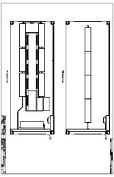
SO<strong>MF</strong> B (Modified)The Mobile Facility Side Opening Type B (Modified) is identical tothe SO<strong>MF</strong> Type B, except that large double doors are installed atthe rear of the mobile facility. The double doors allow largeequipment to be brought into the mobile facility for repair orother work.SO<strong>MF</strong> CThe Mobile Facility Side Opening Type C has one personnel doorat the front end. Each side contains a removable side panelassembly, both side panel assemblies store securely on the roof.Removal of the side panel assemblies allows the SO<strong>MF</strong> Type C tojoin another SO<strong>MF</strong> side by side.INUThe Integration Unit provides a method of joining basic, sideopening and integration unit mobile facilities into a functional,environmentally controlled complex. The INU also serves as acorridor, an electrical power distribution control unit, and aproduction control supervisory/ administrative workspace.The dimensions of the unit are identical to the basic mobile facility.The INU is equipped with 48-in by 76-in end doors, identical to thebasic <strong>MF</strong>. The integration unit mobile facility also features threeremovable side panels of the same size, two on the left side andone on the right side.These doors and panels permit mobile facilities to be attached toeither the end or side of the INU. Different from other MobileFacilities, the INU incorporates a removable window-type airconditioner. oner.7
<strong>MF</strong> SpecificationsMilitary SpecsMIL-M-81957(AS)ISO/ANSI SpecsISO 1496/1 andANSI MH5.1, 5.1.1 and 5.4ASTMDesignation: PS 27 - 95Exterior Dimensions96in. high, 96in. wide,238 1/2 in. longInterior Dimensions84 5/16 in. high x89 13/16 in. wide x232 5/16 in. longExterior FinishGlossy white polyurethaneMaximum Payload15, 800 lbs.Roof LoadsLive load of 660 lbs onan area 24 in. by 12 in.;or 75 lb./ft. 2uniform snow loadDoors48 in. by 76 in.;Located at each endof the mobile facilityTransportabilityAll modesShelter Tare Weight4,200 lbs.Heat TransferInsulated to providea heat transfer coefficientof0.25 BTU/hr. ft. 2/°FTemperature RangeOperation: -40°F toFloor Loads+ 125°F plus solar138 lbs/ft2 uniform loadsload to minimumof +180°F. StorageWall, Roof &-65°F to + 160°FFloor Attachments2,000 lb. pullout andService Life40 inch-lb torque15 years service,20 years storageMODELNO.DESCRIPTIONSPECEXTERIORDIMENSIONSH(in)W(in)L(in)INTERIORDIMENSIONSH(in)W(in)L(in)SHELTERWEIGHT(LBS)PAYLOAD(LBS)OUTLINEDWG.1339AS500-1Side Opening <strong>MF</strong>(SO<strong>MF</strong>)-Type AMIL-M-8195796 96238-1/284-5/1689-13/16232-5/164900 15.800 70065401339AS501-1Side Opening <strong>MF</strong>(SO<strong>MF</strong>)-Type BMIL-M-8195796 96238-1/284-5/1689-13/16232-5/164300 15.700 70065411339AS1101-11339AS1100-1Side Opening <strong>MF</strong>(SO<strong>MF</strong>)-Type CSide Opening <strong>MF</strong>(SO<strong>MF</strong>)-DoubleDoorsMIL-M-81957MIL-M-8195796 9696 9684-5/16238-1/2238-1/284-5/1689-13/1689-13/16232-5/16232-5/164300 15.700 1339AS11014300 15.700 1339AS1100Note: All shelters listed above are nominal 8’W x 8’H x 20’L, ISO shelters are also available in 10’, 30’ and 40’ lengths.8
<strong>NAVAIR</strong> mobile facilities (<strong>MF</strong>s) purchased since 1975comply with applicable International Organization forStandardization (ISO)/American National StandardsInstitute (ANSI) dimensional and structural containerrequirements and the provisions of American Societyfor Testing and Materials (ASTM), Provisional Standard27-95 (PS 27Rigid Wall Relocatable Structures. Standardizationfeatures enhance mobility of tactical shelters andpromote intraservice/interservice coordination andjoint operations. Mobile facilities may be transportedby land, sea, and air and are especially adaptable tocontainer ships and military cargo aircraft. The <strong>MF</strong> is amember of the Department of Defense (DoD) standardfamily of shelters authorized for military service use byDoD Instruction 4500.37.These shelters are designed in accordance withmilitary specification MILISO/ANSI specification 1496/1 and ANSI MH5.1, 5.1.1,and 5.4d. Mobile Facilities Program requirementsdictate that <strong>MF</strong>s be certified in accordance withDepartment offor Safe Container (CSC) certification. The <strong>MF</strong> isincluded as an authorized container for DoD use withthe Joint Committee on Tactical Shelters (JOCOTAS).Facilities are not compatible with rail transit due to thepotential for sustained vibration damage.
We are currently transitioning to the new R134 ECU for the 3 ton unit. The 5 ton unit may be procuredto meet unique user requirements, but is not a standard inventory item. Below you will find data onboth. For publications listed below please download them from the NATEC website. If not availablethrough NATEC check our "Tech Manual" section of our website at www.mobile-facilities.com.Environmental Control Unit (ECU)10R22 ECU - 3 TONNSN: 014423954Part #: 1559AS100-1Nomenclature: Environmental control unit, 3 tonTEC: GEC6Type Designator: A/E 32C-45<strong>MF</strong>G: Environmental SystemsManual : NA 19-60-83Pre-Op’s: NA 19-600-141-6-1MRC’s: NA 19-600-141-6-2R134 ECU - 3 TONNSN: 015502063Part #: 1559AS400-1Nomenclature: Environmentalcontrol unit, 3 tonTEC: GEC6Type Designator: A/E 32C-45 A<strong>MF</strong>G: Environmental SystemsManual : NA 17-1-573Pre-Op’s: NA 17-600-762-6-1MRC’s: NA 17-600-762-6-2R22 ECU - 5 TONNSN: 013552854Part #: 2026AS100-1Nomenclature: Environmental control unit, 5 tonTEC: GEC8Type Designator: A/E 32C-48<strong>MF</strong>G: Environmental SystemsManual : NA 19-60-89Pre-Op’s: NA 19-600-273-6-1MRC’s: NA 19-600-273-6-2R134 ECU - 5 TONNSN: 015521698Part #: 2026AS400-1Nomenclature: Environmentalcontrol unit, 5 tonTEC: GEC8Type Designator: A/E 32C-48 A<strong>MF</strong>G: Environmental SystemsManual : NA 17-1-568Pre-Op’s: NA 17-600-763-6-1MRC’s: NA 17-600-763-6-2
S<strong>MF</strong>CNSN: 6130-01-543-7581Description: 50/60 to 400 HZ Static MobileFrequency ConverterNomenclature: Static Mobile FrequencyConverterMRC: AGAVModel: A/M24M-5P/N: 1000AG1000-1Manuf.: Aviation Ground Equipment Corp.Weight: 3925 lbs.Dimensions: 106" L x 40" W x 65" HTransport: Towed or manually movedINPUTVoltage Range: 440/220 VACConfiguration: 3-PhaseFreq Range: 50 to 60 HzOUTPUTVoltage: AC: 115/200 v, DC: 270 v and 28 vConfiguration: 3-PhaseFrequency: 400 HzOverload: 110% for 60 min/125% for 5 min/150% for 2 min, 200% for 20 secMMG-1AWhen 400 Hz power is required, it is furnished by rotary orsolid state frequency changers . S<strong>MF</strong>Cs (Static MobileFrequency Converters) and MMGs (Mobile MotorGenerators) are used to convert 440/220 VAC 50/60 Hzinput power to 115/200 VAC, 3-phase, 400 Hz and 270 VDCand 28 VDC output power. The S<strong>MF</strong>Cs and MMGs are notself-propelled and must be towed or manually moved. The4-wheel trailers are equipped with tie-down rings,pneumatic tires, a mechanical hand brake, and a tow barfor towing and steering. The S<strong>MF</strong>Cs and MMGs operateworldwide in rugged military environments and support<strong>MF</strong>s on shipboard and shore based sites. In the future theMMG will be replaced by the S<strong>MF</strong>C12S<strong>MF</strong>C
The Program also includes internal 400 Hz frequency converters installed in certainconfigurations depending upon power requirements.ECU-108/ENSN: 6130-01-368-5734Description: 60 to 400 HZ Electronic FrequencyConverterNomenclature: Electronic Frequency ConverterModel: CR-074-3PP/N: 1737AS100-1Manufacturer: UnitronWeight: 250 lbs.Dimensions: 17.5” H x 19” W x 24” DINPUTVoltage Range: 120/208 VRMSConfiguration: 3-Phase, 4 WireFreq Range: 45 to 66 HzOUTPUTVoltage: 120/208 VRMSConfiguration: 3-Phase, 4 WireFrequency: 400 HzPower: 2.5 to 7.5 kVAOverload: 125% for 1 min/150% for 5 secECU-130/FNSN: 6RD-6625-01-552-1659-SXDescription: 400 Hz, 10 kVA FrequencyConverterNomenclature: Electronic Frequency ConverterModel: PS-94-450-1P/N: 80-18007-1Manufacturer: UnitronWeight: 145 lbs.Dimensions: 17.3” H x 19” W x 25.6” DINPUTVoltage Range: 115/200 VRMSConfiguration: 3-Phase, wye, grounded neutralFrequency Range: 30 to 600 HzOUTPUTVoltage: 115/200 VRMSConfiguration: Single PhaseFrequency: 400 HzPower: 10 kVA continuousOverload: 125% for 5 min/175% for 10 sec13
Power Distribution Box (PDB)/Load Bank14The Power Distribution Box (PDB) is the major component of theMobile Facility Program Tactical Electrical Power DistributionSystem. Three 200-KW generators may be connected to the PDB;one in standby and two paralleled and operational. The PDB isconstructed with forklift pockets and lifting rings for ease ofmovement.Normally, the PDB supplies power to Integration Unit MobileFacilities (INU) and Mobile Electric Power Plants, type MMG-1As. Toaccomplish this, each end of the PDB includes seven receptaclesconsisting of six 200-amp and one 100-amp connector. Eachconnector is protected by a weatherproof circuit breaker. Oneexternal weatherproof receptacle rated at 115/120-VAC, 20-amp,single phase, is provided for utility use. It is protected by a 20-ampGround Fault Circuit Interrupter (GFCI) circuit breaker. Power input is120/208-VAC, 1200-amp, 60-Hz, 3-phase wye, 5-wire and the poweroutput is 120/208-vac, 100/200-amp, 60-Hz, 3-phase wye, 5-wire.The PDB weighs 2000-lbs., is 76.5 in. high, 46-in wide, and 120-inlong. Power cables provided with the system connect the generatoradapter panel at each generator to the PDB. This equipment allowsrapid, efficient distribution of electricity from high output generatorsto a large number of smaller electrical loads.Load BankPower Distribution BoxNSN: 6RD-4920-01-559-1148-SXDescription: 200 KW Portable Load BankNomenclature: Load Bank, Portable, 200 KWType Designator: MXU-1004/EPart Number: LPH200D35584Manufacturer: Avtron Aerospace, Inc.Cage: 01014SERD: <strong>MF</strong>256 SM&R Code: PEGGGVolts: 240/480 VACFrequency (Hz): 60 Phase: 3Load Step Resolution (KW): 5, 10, 10, 25, 50, 100Weight: 650 lbs.Dimensions: 47.50" L x 33.75"W x 50.25"HLoad banks are portable, self-contained units that simulate electrical loads for testing power sources such as dieselgenerating systems and Uninterruptible Power Supplies (UPS). Load banks are also used to reduce "wet stacking"problems in diesel engines of backup generating systems. Manufactured elements are made of a corrosion resistantchromium alloy and are fully supported across their entire length on stainless steel support rods with segmentedceramic insulators. Elements are carefully selected to operate at low temperatures to provide extended, reliableperformance, eliminating the need for a "cool down" period after load bank operation.The primary cause of diesel engine failure is "wet-stacking" ("wet" unburned fuel accumulating in the engine"stack"). It is caused by under-loading of the generator. Diesel engines that are lightly loaded, or allowed to idle forlong periods, never reach their recommended operatingtemperature. Over time, unburned fuel coats the combustionchamber, reducing engine rating, efficiency, and life span. Load banks provide minimum load on generators requiredto prevent wet stacking. A preventive maintenance plan that includes load testing of a diesel generator set, willreduce the harmful effects of wet-stacking and increase engine life.
Complexing Mobile Facilities TogetherOne of the most important features of the Program is the ability to complex two or more MobileFacilities (<strong>MF</strong>s) into a functional entity in order to perform a common task. This capability allowsusers to integrate several work functions into one environmentally controlled work space.Complexing is normally accomplished by using a combination of basic mobile facilities, SideOpening Mobile Facilities (SO<strong>MF</strong>), INtegration Unit (INU) mobile facilities and ancillary equipmentsuch as butting kits, walkways, and electrical power distribution cables. Essential ancillaryequipment is provided with the mobile facilities and integration unit mobile facilities inaccordance with requirements identified in the mobile facility complex site plan.The key to mobile facility complexing is the integration unit, which has three removable side panels(two on the left side of the unit and one on the right side). By using a butting kit, basic mobile facilitiescan be joined to each other end-to-end or to an opening in the integration unit mobile facility.16
A specially designed complexing and decomplexing tool (CDT) is used to maneuver individual mobilefacilities in complexing scenarios. The CDT allows <strong>MF</strong>s to be moved a short distance over relatively smoothsurfaces using a forklift, tug or man power.Once mobile facilities andintegration units are joined into acomplex, butting kits areattached between the complexedshelters to form a weather-tightseal. Ancillary equipment such aswalkways and power distributioncables are also installed. Aftercomplexing the shelters,technicians can initiate theequipment checkout process.17
The site plan is a design for installing a number of mobile facilities in a particular space to accomplish aspecific function. It takes into account such operational concepts as the number of shelters involved,integration unit and mobile facility mix, installation space available, utilities required, utilities available,generator sets, power distribution box, etc., and functions supported by the mobile facility complex. A wellconceived site plan is essential to the installation process and efficient operation of the units after installation.Complexing enlarges the entire scope of the Mobile Facility Program. While a single shelter may haverestricted usefulness, an integrated complex can provide unlimited capability.19
Mobile Facilities Program WebsiteThe Mobile Facilities Program has a websiteavailable for commands to access detailedinformation concerning the program.The Website can be reached at:http://www.mobile-facilities.com/20
Mobile Facility Program POCFor more information concerning our program please contact us at:Mobile Facility ProgramAIR 6.7.6.247013 Hinkle CircleBldg 416, Suite 200APatuxent River, MD 20670-1628Air 6.7.6.2 <strong>MF</strong> Program ManagerWork: (301)757-8685DSN: 757-8685Fax: (301)757-5096Email: <strong>MF</strong>ProgMgr@mobile-facilities.comAir 6.7.6.2 <strong>MF</strong> Deputy Program MgrWork: (301)757-0747DSN: 757-0747Fax: (301)757-5096Email: <strong>MF</strong>DepMgr@mobile-facilities.comMobile Facilities Configuration SitesMobile Facilities Configuration SiteNorth Island, CADoDAAC/UIC: N65888Fleet Readiness Center SouthwestNaval Base Coronado, Code 6.7.6.2.0San Diego, CA 92135Work: (619)545-2312DSN: 735-2312Fax: (619)545-4595Email: WestCoast@mobile-facilities.comMobile Facilities Configuration SiteNorfolk, VADoDAAC/UIC: N58070<strong>NAVAIR</strong> <strong>MF</strong>CS NorfolkBldg NM-92, 8581 Patrol RdNorfolk, VA 23511-4213Work: (757)444-7334/5752DSN: 564-7334/5752Fax: (757)444-7132Email: EastCoast@mobile-facilities.com
Mobile Facility Programhttp://www.mobile-facilities.com/