STEER PUSHER ASSEMBLY INSTRUCTIONS
STEER PUSHER ASSEMBLY INSTRUCTIONS
STEER PUSHER ASSEMBLY INSTRUCTIONS

Create successful ePaper yourself
Turn your PDF publications into a flip-book with our unique Google optimized e-Paper software.
<strong>STEER</strong> <strong>PUSHER</strong> <strong>ASSEMBLY</strong> <strong>INSTRUCTIONS</strong>1
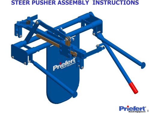
<strong>STEER</strong> <strong>PUSHER</strong> <strong>ASSEMBLY</strong> <strong>INSTRUCTIONS</strong>Assembly #1Step 1: Take the Steer Pusher Assembly #1 andplace it onto the Roping Chute. Next insert the1/2”x3-1/2” bolts to hold the Assembly in place.Support PipeStep 2: Take the Support Pipe and set it intoplace against the vertical pipe at the rear of theRoping Chute. Then attach it to Assembly #1 byusing the 1/2“ nuts provided.HandleRear of RopingChuteRest support pipe against thisvertical pipe on the Roping ChuteStep 3: Rotate Assembly #1 up so that you can securethe Handle to it using the 1/2”x1-1/4” bolt provided.2
<strong>STEER</strong> <strong>PUSHER</strong> <strong>ASSEMBLY</strong> <strong>INSTRUCTIONS</strong>Step 4: Take Steer Pusher Assembly #2 and insert itinto Assembly #1.Step 5: Take Steer Pusher Assembly #3 and insertAssembly’s #1 and #2 into it, then place it down ontothe Roping Chute. Insert the 1/2”x3-1/2” bolts to holdthe Assembly in place.Assembly #3Assembly #2Step 6: Take the other Support Pipe and set itinto place against the vertical pipe at the rear ofthe Roping Chute. Then attach it to Assembly #3by using the 1/2“ nuts provided.Support Pipe3
<strong>STEER</strong> <strong>PUSHER</strong> <strong>ASSEMBLY</strong> <strong>INSTRUCTIONS</strong>Assembly #4Step 7: Take Steer Pusher Assembly #4 andplace it onto the Roping Chute’s top archedbars.Step 8: Secure it into place at the threecircled locations using the 1/2”x2-1/2” boltsprovided.3/8”x1-1/2”x15” Flat BarStep 9: Take the 3/8”x1-1/2”x15” bent Flat Bar andattach it on the inside of the flat bar on Assembly #1and in between the two ears of the Lock Box with the5/8”x1-1/2” bolts provided.NOTE: The bend in the flat bar should be towards theinside when installed.Lock Box4
<strong>STEER</strong> <strong>PUSHER</strong> <strong>ASSEMBLY</strong> <strong>INSTRUCTIONS</strong>Step 10: Take the 3/8”x1-1/2”x8-1/2” bent Flat Bar andattach it on the inside of the flat bar on Assembly #2 andon the outside of Assembly #4 using the 5/8”x1-1/2” boltsprovided. This concludes the Steer Pusher InstallationProcess.3/8”x1-1/2”x8-1/2”Flat BarNOTE: The bend in the flat bar should betowards the inside when installed.Thank you forchoosing a Priefert Product.5