SV 106 User manual - Svantek
SV 106 User manual - Svantek
SV 106 User manual - Svantek
- No tags were found...

You also want an ePaper? Increase the reach of your titles
YUMPU automatically turns print PDFs into web optimized ePapers that Google loves.
<strong>SV</strong>AN <strong>106</strong>Vibration MeterUSER’S MANUAL<strong>SV</strong>ANTEK Sp. z o.o.WARSAW, March 2013
_<strong>SV</strong>AN <strong>106</strong> <strong>User</strong> MANUALNotice: This user’s <strong>manual</strong> presents the software revision named 3.21.03 (cf. the description of theUnit Label position of the Instrument list). The succeeding software revisions (marked with the biggernumbers) can slightly change the view of some displays presented in the text of the <strong>manual</strong>.2
_<strong>SV</strong>AN <strong>106</strong> <strong>User</strong> MANUALCONTENTS1. INTRODUCTION 61.1. <strong>SV</strong>AN <strong>106</strong> main features 61.2. Accessories included 71.3. Accessories available 72. MANUAL CONTROL OF THE INSTRUMENT 82.1 Control push-buttons on the front panel 82.2 Input and output sockets of the instrument 123. SETTING THE INSTRUMENT 133.1. Basics of the instrument’s control 133.2. Powering of the instrument 163.3. Initial Setup of the instrument 173.4. Icons description 183.5. Memory organisation 194. FUNCTIONS OF THE INSTRUMENT – Function 224.1. Measurement functions of the instrument - Measurement Function 224.2. Instrument’s calibration – Calibration 234.2.1. Downloading and uploading TEDS data – TEDS 234.2.2. Calibration of the instrument channels – Channel x 234.2.3. Calibration by transducer's sensitivity – Calibr. By Sensitivity 244.2.4. Calibration by measurement – Calibr. By Measurement 254.2.5. History of the calibrations – Calibration History 264.2.6. Clear calibration records - Clear Calibr. History 275. MEASUREMENT PARAMETERS SETTING – Measurement 285.1 Selection of measurement parameters - General Settings 295.2 Setting the parameters for dose measurements – HAV/WBV Dosimeter 325.3 Setting parameters in a channels – Channels Setup 335.3.1 Assignment channels for the accelerometer axis - Channel/Axis Mapping 345.3.2 Setting parameters for channels – Channel x 345.4 Setting the vector parameters – Vectors Setup 355.5 Setting the data logging functionality – Data Logging 365.6 The results history logging 375.6.1 Data logger programming – Logger Setup 375.6.2 Results selection – Logger Results 385.6.3 Logger trigger parameters setup – Logger Trigger 405.6.4 Event recording setup – Event Recording 425.6.5 The marker setup – Marker Setup 445.7 Wave recording 453
_<strong>SV</strong>AN <strong>106</strong> <strong>User</strong> MANUAL5.8 Measure trigger parameters selection – Measure Trigger 465.9 Settings whole body measurements with the use of seat accelerometer – SEAT 495.10 The alarm trigger setting– Alarm Trigger 495.11 Programming the instrument’s internal timer – Timer 495.11.1 Description of an example timer function execution 506. DATA AVAILABLE ON THE DISPLAY – Display 526.1 Selection of the modes of measurement results presentation - Display Modes 526.1.1 Main presentation mode 536.2 Setting the logger presentation parameters – Logger Scale 576.3 Setting the result presentation scale – Results Scale 586.4 Setting the display brightness and power saver- Screen 597. SAVING THE MEASUREMENT RESULTS – File 607.1 Saving files in the instrument’s memory or external memory 617.2 Managing the files saved in the internal and external memory – File Manager 637.2.1 Setting the directory for saving files – Set Working Directory 657.2.2 Creating new catalogue and new file 657.2.3 Deleting all files from Internal memory – Delete All 667.2.4 Merging result and setup files memory – Defragmentation 667.2.5 Opening file/catalogue – Open 677.2.6 Deleting file/catalogue – Delete 677.2.7 Copying file/catalogue – Copy 687.2.8 Moving file/catalogue – Move 687.2.9 Renaming file/catalogue – Rename 687.2.10 Information about file/catalogue – Info 697.3 Managing the setup files – Setup Manager 697.3.1 Saving the setup files 697.3.2 Operations on the setup files 707.4 Controlling data storing in the instrument’s memory - Save Options 717.5 Options for setup files - Setup Options 728. SETTINGS OF THE INSTRUMENT PARAMETERS – Instrument 738.1 Selection of keyboard modes – Keyboard 738.2 Setting parameters of the I/O port - Multifunction I/O 748.3 Checking the powering of the instrument – Power Supply 758.4 Programming the instrument’s internal Real Time Clock – RTC 768.5 Activating the remote control error confirmation - Remote Control 768.6 Transducer's compensation activation – Transducers 778.7 Checking the specification of the instrument - Unit Label 779. AUXILIARY SETTINGS – Auxiliary Setup 784
_<strong>SV</strong>AN <strong>106</strong> <strong>User</strong> MANUAL9.4. Setting the language of the user interface – Language 789.5. Return to the factory settings – Factory Settings 789.6. Setting the scope of instrument's functions — Instrument Mode 799.7. Reference signal in vibration measurements - Reference Levels 809.8. <strong>User</strong> filter setting – <strong>User</strong> Filters 809.9. Selection of the Vibration units - Vibration Units 819.10. Warnings selection – Warnings 8110. 1/1 AND 1/3 OCTAVE ANALYSER 8210.1. Selection of 1/1 Octave or 1/3 Octave analysis mode 8210.2. Setting the parameters of 1/1 Octave and 1/3 Octave analysis - 8210.3. Saving of 1/1 Octave and 1/3 Octave analysis results in the logger’s file - LoggerResults 8310.4. Selection of 1/1 Octave and 1/3 Octave bandpass results as triggering source 8310.5. Display options in 1/1 Octave and 1/3 Octave analysis mode 8410.6. Presentation of 1/1 Octave and 1/3 Octave analysis results 8410.7. Setting the scale of the spectrum results presentation – Spectrum Scale 8510.8. Setting parameters of the spectrum presentation - Spectrum View 8710.9. Selection of channels for presentation – Multichannel View 8710.10. Setting parameters for total values – Total Values 8810.11. Setting user filter coefficients for 1/1 Octave and 1/3 Octave analysis – <strong>User</strong> Filters 8811. DOSIMETER FUNCTION 9011.1. Setting parameters for dose measurements – HAV/WBV Dosimeter 9011.2. Setting parameters for channels – Channel x 9111.3. Dosimeter presentation mode 9211.4. Calculation of hand-arm and whole-body daily results – Calculator 925
_<strong>SV</strong>AN <strong>106</strong> <strong>User</strong> MANUAL1. INTRODUCTIONThe <strong>SV</strong> <strong>106</strong> is a new six-channel human vibration meter andanalyser. The instrument meets the ISO 8041:2005 standardand it is an ideal choice for measurements according to ISO2631-1,2&5 and ISO 5349.Using the computational power of its digital signal processorthe <strong>SV</strong>AN <strong>106</strong> instrument can, simultaneously to the broadband meter mode, perform real time 1/1 Octave or1/3 Octave analysis.Advanced time-history logging and time-domain signalrecording (according to ISO 2631-5) to the built-in Micro SDflash card give almost unlimited capabilities of data storage.Results can be easily downloaded to PC using the high speedUSB interface and the SvanPC++ software.The Whole-Body vibration measurement is now even easier thanks to the <strong>SV</strong> 38V seat-accelerometer whichcan be placed directly on the seat-cushion, on the floor or fixed to the back of the seat.The <strong>SV</strong> 50 set with triaxial accelerometer enables Hand-Arm vibration measurements regardless of the typeof evaluated tool.Additionally, for measurements of very high impulse vibration the special adapter SA 55, with low passmechanical filter protecting accelerometer from DC shift effect is available. Evaluation of the grip force will bepossible with the dedicated “integrated adapter” <strong>SV</strong> 105 (under development).Fast USB 1.1 interface (12 MHz) creates real time link for the PC "front-end" application of the <strong>SV</strong>AN <strong>106</strong>instrument. The measurement results can be downloaded to PC using the above mentioned interfaces.The instrument is powered from four AA standard alkaline or rechargeable batteries (i.e. NiMH – a separatecharger is required). Powering the instrument from the USB interface is also possible. Robust and lightweightdesign accomplishes the exceptional features of this new generation human vibration exposure instrument.1.1. <strong>SV</strong>AN <strong>106</strong> main features Human Vibration measurements meeting ISO 8041:2005, ISO 2631-1,2&5 (including VDV and MTVV) and ISO 5349 Six channels for acceleration (IEPE type) and two channels for force measurements Whole-Body measurements:- Low-cost seat accelerometer <strong>SV</strong> 38V Hand-Arm measurements:- <strong>SV</strong> 50 triaxial accelerometer with set of hand grip and screw clamp adapters- SA 55 adapter with triaxial mechanical filter6
_<strong>SV</strong>AN <strong>106</strong> <strong>User</strong> MANUAL- <strong>SV</strong> 105 integrated triaxial accelerometer adapter including grip force sensorTime-domain signal waveform recording (meeting ISO 2631-5) as option1/1 octave and 1/3 octave spectral calculations (as option)Advanced data logger including spectral analysisMicro SD flash card for almost unlimited mass data storageUSB 1.1 Client interfaceIntegration time programmable up to 24 hSvanPC++ software for easy instrument setup and data downloadEasy to use, operator friendly interface with high contrast full colour displayPocket size (140 x 83 x 33 millimetres – 5.5 x 3.3 x 1.3 inches)Light weight (only 390 grams – 13.9 oz) including 4 x AA batteries1.2. Accessories includedThe <strong>SV</strong> <strong>106</strong> set consist of the following parts: <strong>SV</strong> <strong>106</strong> instrument with 4 AA batteries or 4 rechargeable AA batteries installed. SC 56 mini USB 1.1 cable (typical 2m) SC 118 LEMO 4-pin to LEMO 5-pin connector <strong>SV</strong> 38V triaxial accelerometer for Whole—Body measurements (MEMS type) <strong>SV</strong> 105 integrated triaxial Hand-Arm adapter with grip force sensor (MEMS type)1.3. Accessories available SA 54 Power supply unit with USB Connector SC 38 Cable used to connect the <strong>SV</strong> 50 triaxial accelerometer with the <strong>SV</strong><strong>106</strong> (4 pinMicrotech to LEMO 4 pin (typical 2.7 m)) SA 50 Hand-Arm measurement adapter, "shaped base" (for <strong>SV</strong> 3023M2 accelerometer) SA 51 Hand-Arm measurement adapter, "flat base" (for <strong>SV</strong> 3023M2 accelerometer) SA 52 Hand-Arm measurement adapter, "direct" (for the <strong>SV</strong> 3023M2 accelerometer) SC 14 LEMO 5 pin to LEMO 5 pin extension cable (10 m) SA 55 adapter with low pass mechanical filter <strong>SV</strong> 39A\L Seat Accelerometer (including <strong>SV</strong> 3143M1 and SC 38 cable) <strong>SV</strong> 50 set for Hand-Arm measurement (Dytran accelerometer 3023M2; adapters SA 50,SA 51, SA 52 with clamps and accessories) <strong>SV</strong> 111 vibration calibrator (100 rad/1ms -2 , 500 rad/10ms -2 , 1000 rad/10ms -2 )7
_<strong>SV</strong>AN <strong>106</strong> <strong>User</strong> MANUAL2. MANUAL CONTROL OF THE INSTRUMENTControl of the instrument has been developed in a fully interactive manner. The user can operate theinstrument by selecting the appropriate position from the selected Menu list. Thanks to that, the number ofthe control push-buttons of the instrument has been reduced to nine for ease of use and convenience.2.1 Control push-buttons on the front panelThe following control push-buttons are located on the frontpanel of the instrument:, (), [],, (), [],, [Markers], [Markers],,,,.The name given in (...) brackets denotes the second push-button function which is available after pressing itin conjunction (or in sequence) with the push-button. For the first two push-buttons the name givenin square brackets […] denotes also the third push-button function which is available after pressing it inconjunction (or in sequence) with the push-button.The second function of a push-button (written in red colour on a push-button) can beused when the push-button is pressed. This push-button can be used in twodifferent ways: as Shift like in a computer keyboard (e.g. while typing the filename); both and the second push-button must be pressed together (two fingeroperation); as 2nd Fun; this push-button can be pressed and released before pressing thesecond one or pressed in parallel (while operating in “2nd Fun” mode, see thefollowing notice) with the second push-button (one finger operation).The push-button pressed in conjunction with enables the user to enter theMarkers on the plots during the measurement.This push-button enables the user to choose the third push-button function in case of[] and [] push-buttons. In order to select the third function the user mustpress the and the second push-button simultaneously.Notice: Simultaneously pressing the and push-buttons switches theinstrument on or off.8
_<strong>SV</strong>AN <strong>106</strong> <strong>User</strong> MANUALThis push-button enables the user to start the measurement process when theinstrument is not measuring or to stop it when the instrument is in course of themeasurement. It is also possible to set the mode of this push-button such that in order tostart or stop the measurements the user has to press it simultaneously with the push-button.Notice: Changing the push-button mode is performed in the Keyboard Settingswindow of the Instrument list (see description of the Instrument list).This push-button enables the user to enter the selected position shown on the screenMenu list or to confirm selected settings. Some additional functions of this push-buttonwill be described in the following chapters of this <strong>manual</strong>.()This push-button (pressed together with ) enables the user to enter the main listcontaining six sub-lists: Function, Measurement, Display, File, Instrument andAuxiliary Setup. Each of the mentioned above menu lists consists of sub-lists, elementsand data windows. These main sub-lists will be described in detail in the followingchapters of the <strong>manual</strong>. Double pressing the push-button enters a listcontaining the last eight opened sub-lists. It often speeds up control of the instrument asthe user has faster access to the most frequently used sub-lists for easy navigation.[]This push-button (pressed together with ) enables the user to save measurementresults as a file in the instrument’s internal memory or on the SD-card.This push-button closes the control lists, sub-lists or windows. It acts in an oppositemanner to the push-button. When the window is closed after pressing the push-button, any changes made in it are ignored in almost all cases.([Cal.])This push-button (pressed together with ) opens the Calibration sub-list.[]This push-button enables the user to jump to pause or break the measurement processtemporarily. If there is no current running measurement in progress this push-buttonopens the Setup Manager menu, These push-buttons enable the user specifically to: select the column in a multi column parameter list; select the parameter value in an active position (e.g. filter Z, A or C, Integrationperiod: 1s, 2s, 3s, … etc.); control the cursor in Spectrum and Logger modes of result’s presentation; select the position of the character in the text editing mode; activate markers 2 and 3 speed up changing the numerical values of the parameters when pressed and held.9
_<strong>SV</strong>AN <strong>106</strong> <strong>User</strong> MANUAL(, )The , push-buttons pressed in conjunction (or in sequence) with enable the user specifically to: speed up changing the numerical values of the parameters (i.e. the step is increasedfrom 1 to 10 in the setting of Start Delay - path: Menu / Measurement / GeneralSettings / Start Delay); jump to the last or first character of an edited text line in the text edition modes,[, ]The , push-buttons pressed in conjunction (or in sequence) with enablethe user specifically to: select the parameters value in the multi column list, insert or delete a character in the text editing screen., The , push-buttons enable the user specifically to: select lines in the list; select the correct character from the list in the text edition screen; activate markers 1 and 4(, )The , push-buttons pressed in conjunction (or in sequence) with enable the user specifically to: change relationship between the Y-axis and X-axis of all plots presented on thescreen[, ]The , push-buttons pressed in conjunction (or in sequence) with enablethe user specifically to: change the mode of result’s presentation; programme the Real Time Clock (RTC) and Timer;[Info]The push-button (simultaneous pressing the, push-buttons) opens the window with thehelp information in the measurement display modes.[Markers]The Markers combination buttons enable the user to mark special events whichoccurred during the performed measurements. Event function is active only when theLogger is active. In order to activate the markers the logger has to be switched on (path: / Measurement / General Settings / Logger Mode = Logger) and one or morelogger results (PEAK, P–P, MAX, RMS, VDV) in profiles have to be activated (path: / Measurement / Data Logging / Logger Results).10
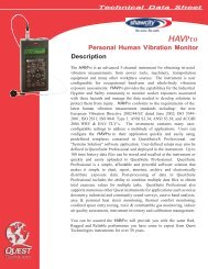
_<strong>SV</strong>AN <strong>106</strong> <strong>User</strong> MANUALIn order to enter the marker mode the user must press and push-buttons simultaneously during the measurement. Then four availablemarkers appear on the screen. To choose marker number 1 the user mustpress push button (number 2 - , number - 3 and number 4 -).The markers disappear automatically and the chosen marker is activated(after pressing + again, the active marker number will behighlighted). In order to switch off the marker, the user has to press + and press the arrow push-button, which refers to the marker to beswitched off. / The current state of the markers is indicated in the logger file (cf. App. B fordetails) and can be used to show them with the help of the dedicatedpresentation software.An example presentation of the markers on the time history plot is shownbelow (to view a plot with markers the user has to transfer data to theappropriate software such as SvanPC++).8070605040302013:30:00 13:30:09 13:30:17 13:30:26 13:30:35 13:30:43 13:30:52LeqMarker 1Marker 2Marker 3Marker 411
_<strong>SV</strong>AN <strong>106</strong> <strong>User</strong> MANUAL2.2 Input and output sockets of the instrumentTop cover of the instrumentThe measurement inputs are placed on the top cover of theinstrument: two 5-pin Lemo compatible sockets typeENB.0B.304 for Channels 1–3 and Channels 4-6, all withIEPE power supply for the accelerometers.Bottom cover of the instrumentIn the bottom cover there are two sockets, placed from theleft to the right as follows: USB Device 1.1 interface andmulti-purpose input / output socket I/O.The USB Device 1.1 interface is the serial interface working with 12 MHz clock. Thanks to its speed, it iswidely used in all PCs. In the instrument, the standard 4-pin socket is used described in more detail inAppendix C.The additional multi-purpose input / output socket, called I/O, is a two-pin jack socket. On this socket, in thecase when the Analogue Output functionality is selected, the signal from the input of the analogue / digitalconverter (before any frequency correction) is available. This signal can be recorded using a magneticrecorder or observed on an oscilloscope. The Digital Input as another functionality serves as the externaltrigger, while the Digital Output is used to generate the trigger pulse or alarm pulse from the instrument.Notice: Switch the power off before connecting the instrument to any other device (e.g. aprinter or a Personal Computer).12
_<strong>SV</strong>AN <strong>106</strong> <strong>User</strong> MANUAL3. SETTING THE INSTRUMENTIn order to perform measurements using the instrument the user only has to connect the propertransducer(s) and to switch the power on by means of the and push-buttons at the sametime.3.1. Basics of the instrument’s controlThe instrument is controlled by means of nine push-buttons on the keyboard. Using these push-buttons theuser can access all available functions and change the value of all available parameters. The functions areplaced in a system of lists and sub-lists.The instrument's menu consists of different type of windows, which include: main menu list, sub-menu list,option list, parameter list, text editor window, information window and file manager window with filecommand list.Main menuThe main list contains the headers of seven lists, which also contain sublistsor positions. The main list is opened after pressing the pushbutton.This list contains the following sub-lists: Function, Measurement,Display, File, Instrument, Auxiliary Setup and Calculator.Position selectionThe desired position in menu list is selectedby means of the or pushbuttons.Entering positionAfter the selection of the desired position inthe menu list, the user has to press the push-button in order to enter it.After this operation a new sub-menu, optionlist, parameter list or information windowappears on the display.13
_<strong>SV</strong>AN <strong>106</strong> <strong>User</strong> MANUALList of parametersThe parameter list contains parameters for which the user may select thevalue from the available range. Pressing the push-buttonenables the user to access the above mentioned sub-lists.• The desired position in a list is accessed after pressing the or push-button.• The change of the value in a selected position is performed by the or push-buttons (or pressed together with ).If the parameter has a numerical value the user may keep pressing the or push-buttons (orpressed together with ) longer than 1 second to speed up the selection. In this case the parameterstarts to change automatically until the user releases the pressed buttons.The user may change the numerical parameter value with a larger step (usually 10, 20) by means of the or push-buttons pressed together with .Option listThe option list consists of different options, from which only one may beselected. The selection of the option is performed as follows. The user hasto highlight the desired option by means of the or push-buttonsand then press . This option becomes active and the list isclosed. When the user re-enters this list again, the last selected option willbe marked.Matrix of parametersWhen the list of parameters consists of more than one column the user maychange:• column by means of or • line in the same column by means of or • value in a selected position by means of or with • all values in the same column by means of or with • all values in the same line by means of or with .Complex parametersSome parameters like Start Hour, Start Dayetc. are complex (consisting of more than onevalue field). The selection of values for suchparameters is performed in a special window,which is opened with the or pushbuttons.In the special window the value isselected with the , or , push-buttons and then is confirmed by pressing.14
_<strong>SV</strong>AN <strong>106</strong> <strong>User</strong> MANUALIn all cases the push-button is used for confirmation of theselection in a position and for closing the opened sub-list.The sub-list is closed ignoring changes made in the list by pressing the push-button.Information windowSome windows inform the user about the state of the instrument, availablememory, none existing files or loggers, standards fulfilled by the unit, etc. Inorder to scroll through the list, the user has to use the or pushbuttons.In order to close such a window, the user has to press .Text edition windowThere are also windows in which the user may edit some text (i.e. the nameof the file). This window contains help information to guide the user on howto edit the text. The character that is displayed inversely may be edited.• One can select the position of the character in the edited text using the, push-buttons.• The available ASCII characters can be changed using the or push-button. The subsequent digits, underline, upper case letters andspace appear on the display in the inversely displayed position aftereach press of the above mentioned push-buttons.• One can insert or delete the position in the edited text using the , push-buttons pressed together with .Help informationIn most windows the last line or several linescontain help information. It informs the user howto select or modify the parameter’s value,change the character in the text line etc.15
_<strong>SV</strong>AN <strong>106</strong> <strong>User</strong> MANUALInactive parametersIf some functions or parameters are notavailable, the positions in the menu orparameter lists linked with this function orparameter become inactive (their colour becamegrey). For example, if Dosimeter (path: / Measurement / General Settings / Dosimeter:Off) is switched off the HAV/WBV Dosimeterline is not active!The Grey colour of a position means that thisparameter has a single value and it is notpossible to change it.Simple and advanced menu modesThere are two instrument modes, which definethe scope of available functions: Simple Modeand Advanced Mode. These modes can beselected in the Instrument Mode window of theAuxiliary Setup menu. Simple Mode definesthe basic instrument functions, while theAdvanced Mode defines the full scope offunctions. Many windows can have differentviews. To the right is an example of theMeasurement window for simple and advancedmodes...3.2. Powering of the instrumentThe <strong>SV</strong>AN <strong>106</strong> can be powered by one of the following sources: Four AA standard size internal batteries. In the case of alkaline type, a new fully charged set canoperate more than 12 h (6.0 V / 1.6 Ah). Instead of the ordinary alkaline cells, four AA rechargeablebatteries can be used (a separate external charger is required for charging them). In this case, usingthe best NiMH type, the operation time can be increased up to 16 h (4.8 V / 2.6 Ah) USB interface – 500 mA HUBIn the Power Supply window of the Instrument list the user can see theinformation about the current power source.When the instrument is powered from its internal batteries, the “Battery”icon is presented on the top line of the display. When voltage of thebatteries is too low for reliable measurements, the icon flashes or duringattempt to switch the instrument on the Low power message occurs on thedisplay for 2 seconds and the instrument switches off by itself. To changethe batteries the user has to switch off the instrument, take off the blackbottom cover of the instrument, unscrew battery cover, slide the batterytubes out, change the batteries taking care to observe the correct polarityand reassemble the parts of the instrument. Fully charged set of 4 batteriesensure more than 12 hours of continuous operation of the instrument (with16
_<strong>SV</strong>AN <strong>106</strong> <strong>User</strong> MANUALDim LCD switched on). The battery condition can be checked by means ofthe Battery function. It is also presented continuously on the top line ofdisplay by means of the “Battery” icon.When there is a connection to the USB interface (USB Device socket isconnected by means of the cable to a PC or a USB power supply), the“Computer” icon is presented on the top of the display and in the Batterywindow there is the message USB Power: 0.00V.Notice: In the case when the “Battery” icon is red it is strongly recommended to use theexternal power adapter or USB interface as soon as possible. to ensure reliable operation. If nosuitable external power source is provided the instrument will be switched off automaticallyafter a short time!Prolonging the internal source of the instrument’s power can be achieved by reducing the brightness of thescreen when possible. The settings of Brightness and power saver function may be done in theScreen Setup window (path: / Display / Screen).3.3. Initial Setup of the instrumentSwitching the instrument onTo switch the power on the user should press the and push-buttons at the same time. The instrument goes the self-test routine afterswitching on (displaying the manufacturer and the name of the instrument)and then it enters the Select Setup window. This window enables the user toselect the predefined setup for specific measurements. To ignore theselection press the push-button.After selecting or skipping the predefined setup the unit has to warm-up forone minute and then the measurement screen with two results appears.Press to bypass the warm up time and go straight to themeasurement start if required.Starting measurementTo start a measurement the user has topress the push-button. Theresult of the measurement is displayedwith the unit of the measurement in socalledtwo profile mode. Two results modeis always available for most Functions ofthe instrument.17
_<strong>SV</strong>AN <strong>106</strong> <strong>User</strong> MANUALPresentation modesThe results of the measurements can bealso presented in the 6 Channels or3 Profiles modes. In these modes theresults for six channels or three profilesare presented on the screen. The usercan switch the presentation modes bymeans of the and , pushbuttonspressed simultaneously.Default settings measurements:The default settings (set up by the manufacturer) for the profiles of all channels are as follows:signal type: Type: IEPE;weighting filter: Filter: Wd;type of the RMS detector: 1.0s;dose meter: 1-3 Dosimeter: WBV; 4-6 Dosimeter: HAV.The user can change all the above mentioned settings using the Measurement list. The instrumentremembers all made changes. Return to the default settings (set up by the manufacturer) is possible afterthe execution of the Factory Settings position available in the Auxiliary Setup list.3.4. Icons descriptionDescription of the instrument stateAdditional information about the instrument’s state is given by meansof the row of icons visible in the top of the display.The type of measurement function and the measurement mode (LM,DLM, 1/1 and 1/3 etc.) as well as the real time clock (RTC) is alsodisplayed in the same line together with icons.The meanings of the icons are as follows:“play” icon is displayed when themeasurement is started.“plug” icon is displayed when theinstrument is powered from the externalsource.“stop” icon is displayed when themeasurement is stopped.“Internal memory” icon is displayed wheninternal memory is assigned for file saving.18
_<strong>SV</strong>AN <strong>106</strong> <strong>User</strong> MANUALThe content of each memory type can be checked with the help of the File Manager or Setup Managerfunction of the File menu.The File Manager is used for checking thecontents of the memory and for operatingon result and logger files such as: open,delete, copy, move, rename, create newfiles or catalogues and display file andcatalogue information.Memory selectionTo change the memory type one shouldpress the push-button in theFile Manager window then select thememory type by means of the , push-buttons and finally press .The files are saved in the Memory and in the catalogue which was set up as the working directory. Theworking Memory type is displayed as the icon in the left position of the icon line.“Internal” memory icon is displayed when internal memory was assigned for filesaving.“SD Card” icon is displayed when external micro SD card memory was assigned forfile saving. The micro SD card should be necessary inserted.The working directory is described in the top line of the File Managerwindow.To change the working directory and/or working memory the user shouldselect the Memory type and in case of the micro SD Card the desireddirectory and press the push-button. Then in the opened windowwith the command list to select the Set Working Directory position andpress the push-button again. The icon on the upper line and thedirectory path on the bottom line will be changed accordingly. The samemethod is applied for changing directory for micro SD Card memory.There are two options for storing result data in the internal or external memory. One option is to press push-button immediately after the measurement. Another option is to create in theFile Manager window.After pressing the push-button the Save Results window appears.20
_<strong>SV</strong>AN <strong>106</strong> <strong>User</strong> MANUALAfter pressing the push-button theSave Results window appears. In theSave Results window the user can enter aname for the result file or choose automaticname generation option.The measurement configuration Setup files can also be stored by means of the push-button and bycreating the in the Setup Manager list. The logger, wave and event files are createdautomatically in the assigned directory on the external memory drive.21
_<strong>SV</strong>AN <strong>106</strong> <strong>User</strong> MANUAL4. FUNCTIONS OF THE INSTRUMENT – FunctionThe Function list contains the elementsthat enable the user to select themeasurement mode of the instrument andperform calibration of it’s measurementchannels. In order to select the Functionlist the user has to press the pushbutton,select the Function text and press. The Function list contains twoelements: Measurement Function andCalibration.The Function list consists of:Measurement FunctionCalibrationenables the user to select the mode of the instrument;enables the user to perform a calibration of instrument’s measurementchannels.4.1. Measurement functions of the instrument - Measurement FunctionThe main function of the instrument is the measurement of broad band Vibration level (Level Meter) meetingthe ISO 8041:2005 standard. The instrument can also be used for medium to long-term vibration monitoringusing the huge capacity data logger in which all the measurement results are stored.The user may also use 1/1 and 1/3 real time octave band analysis functions. These functions broaden themain Level Meter functions of the instrument, because 1/1 and 1/3 octave analysis is performed togetherwith all calculations of Level Meter functions.In all the above functions it is additionally possible to perform vibration dose measurements. Doseparameters are setting up in HAV/WBV Dosimeter window (path: / Measurement).In order to select the required function theuser has to enter theMeasurement Function list. After enteringthe Measurement Function list, the set ofthe available functions appears on thedisplay: Level Meter. Currently activefunction is marked.The type of measurement function and the measurement mode is displayed at the upper line of the screen:- LM Level Meter,- 1/1 1/1 Octave,- 1/3 1/3 Octave,- DLM Dose & Level Meter,- D1/1 Dose & 1/1 Octave,- D1/3 Dose & 1/3 Octave.Optional measurement functions that broaden the application of the instrument can be easily installed. Theseoptions can be initially supplied by the manufacturer or purchased later and added by the user.22
_<strong>SV</strong>AN <strong>106</strong> <strong>User</strong> MANUALNotice: It is not possible to change the measurement function during a measurement run. Inthis case the instrument displays for about 3 seconds the text: “Measurement in Progress”.In order to change the mode of the instrument the current measurement in progress must befinished!4.2. Instrument’s calibration – CalibrationThe instrument is factory calibrated with thesupplied accelerometers. In case of usingother transducers calibration of themeasurement channels should beperformed by the user. Periodic calibrationof standard accelerometers is also required.In order to select the calibration function theuser has to enter the Calibration sub-list.The Calibration list consists of six positions: Channel 1, Channel 2 … Channel 6 which are used toperform the individual calibration of each channel of the instrument.4.2.1. Downloading and uploading TEDS data – TEDSIf an accelerometer with new TEDS data is connected before switching the instrument on the TEDS data aredownloaded automatically. TEDS data usually include: serial number, manufacturer name, calibration factor,etc.The TEDS position enables the user toDownload TEDS Data, when theaccelerometer is connected duringinstrument’s working session. It enablesalso to Upload TEDS Data from theinstrument to the accelerometer’s TEDSmemory - calibration results, performed byuser. 4.2.2. Calibration of the instrument channels – Channel xThe Channel x sub-list consists of fourpositions: Calibr. By Sensitivity, Calibr.By Measurement, which are used toperform the calibration, Calibration Historyused for checking the parameters of theprevious calibrations and Clear Calibr.History to delete previous calibrationinformation.23
_<strong>SV</strong>AN <strong>106</strong> <strong>User</strong> MANUALNotice: The calibration factor is always added to the results in the Level Meter, 1/1 Octave,1/3 Octave, FFT modes.Notice: The calibration level and the calibration result are expressed in different unitsdepending on the settings of the instrument. The metric or non-metric Vibration units are set inthe Vibration Units window (path: / Auxiliary Setup / Vibration Units). Additionally, thelinear or logarithmic units are set in the Display Scale window (path: / Display /Display Scale).Notice: It is not possible to calibrate the instrument during the execution of the measurements.It is possible to open different lists and sub-lists but the positions in these lists are not displayedinversely and so - not accessible. The “►” icon indicates that the instrument is in themeasurement process. In order to change the sensitivity the current measurement in progressmust be finished!4.2.3. Calibration by transducer's sensitivity – Calibr. By SensitivityCalibration by introducing the accelerometer’s individual sensitivity can beperformed in the following way:1. Select this type of the calibration (highlight the Calibr. By Sensitivitytext) from the Calibration sub-list and press the push-button.2. Set the sensitivity of the accelerometer using information taken from itscalibration certificate using the , push-buttons (or combinationof the and , push-buttons).The calibration factor is calculated, after pressing the , pushbuttons,in the relation to 10.0 mV / ms -2 . For the sensitivity of theaccelerometer higher than 10.0 mV / ms -2 the calibration factor will alwaysbe negative.For the sensitivity of the accelerometer lower than 10.0 mV / ms -2 thecalibration factor will always be positive.The lowest applicable value of the sensitivity to be introduced is equal to10.0 V / ms -2 (it conforms to the calibration factor equal to 60.0 dB) and thehighest one is equal to 10.0 V / ms -2 (calibration factor equal to -60.0 dB).3. Press to save the selected calibration factor. Press to return to the Calibration sub-listwithout saving any changes made in this window.24
_<strong>SV</strong>AN <strong>106</strong> <strong>User</strong> MANUAL4.2.4. Calibration by measurement – Calibr. By MeasurementCalibration by actual measurements can be done in the following way:1. Select the calibration by measurement (highlight the Calibr.By Measurement text) from the Calibration sub-list and press.2. Select required filter: for hand-armtransducer – BL Wh, for whole-bodytransducer – BL Wk or equivalent.3. Select the calibrator signal level.4. Attach the vibration calibrator to the instrument’s accelerometer.5. Switch on the calibrator and wait approximately 30 seconds beforestarting the calibration measurement.6. Start the calibration measurement by pressing the pushbutton.The measurement starts after 5 secondsdelay. The calibration measurement time isalso predefined to 5 seconds. During thecalibration period the and push-buttons do not operate but it is possibleto stop the measurement using the push-button. Waiting for thecalibration measurement to begin, a Delay iscounted down. At the end of themeasurement, its result is displayed on thedisplay in the bottom line.It is recommended to repeat the calibration measurement a few times to ensure the integrity of thecalibration. The obtained results should be almost identical (with 0.1 dB difference). Some possible reasonsfor unstable results are as follows:the accelerometer is not properly attached to the calibrator,there are external disturbances,the calibrator or the measurement channel (the accelerometer or the instrument itself) are damaged.25
_<strong>SV</strong>AN <strong>106</strong> <strong>User</strong> MANUALNotice: During the calibration measurement, the external disturbances (vibrations or acousticnoise) should not exceed a value of 100 dB.7. Press in order to accept the calibration measurement result.The calibration factor is calculated, stored and displayed after pressing the push-button.4.2.5. History of the calibrations – Calibration HistoryThe Calibration History window displaysup to ten last calibration records.In order to review the calibration record, the user has to use the , push-buttons. The opened window will contain the date and time of theperformed calibration measurement, the way the calibration was done(Calibr. By Measurement or Calibr. By Sensitivity) and the calibrationfactor (Calibration Factor) that was obtained.If calibration measurements were not performed the Calibration Historywindow does not contain any records. The content of this window is clearedafter the Clear Calibr. History operation.26
_<strong>SV</strong>AN <strong>106</strong> <strong>User</strong> MANUAL4.2.6. Clear calibration records - Clear Calibr. HistoryThe user can clear all stored calibrations records. In order to do this theuser has to choose the position Clear Calibr. History in the Calibrationsub-list and press to perform this operation.The instrument requests confirmation of the operation. The next pressing ofthe push-button, when the No option is selected closes thewindow and returns the instrument to the Calibration sub-list. If Yes isselected the pressing will delete the history and return theinstrument to the previous menu.After Clear Calibr. History operation has been performed theCalibration History window does not contain any more records.27
_<strong>SV</strong>AN <strong>106</strong> <strong>User</strong> MANUAL5. MEASUREMENT PARAMETERS SETTING – MeasurementThe Measurement list contains theelements, which enable the user toprogramme the measurement parametersfor all channels and profiles. TheMeasurement list appears after pressingthe push-button, selecting theMeasurement text and pressing .The Measurement list and some of sub list (General Settings andData Logging) contents depend on Instrument Mode selection from menuAuxiliary Setup: Simple Mode or Advanced Mode. In Advanced Modesome additional functions like triggering, markers, event and waverecording appear.The Measurement list consists of:General Settingsenables the user to select the general measurement parameters for allchannels;HAV/WBV Dosimeter enables the user to set up the parameters for vibration dose measurements;Channels Setupenables the user to program the individual parameters for channels;Vectors Setupenables the user to program the individual parameters for vectorscalculations;Data Loggingenables the user to program the logger functions – measurements loggingand signal recording;Measure Triggerenables the user to set the parameters of measure trigger. Position appearsonly in the advanced instrument mode;SEATenables the user to program the measurements with the use of specialSEAT accelerometer.:Notice: Any parameter in the lists of the Measurement menucan be changed only when the instrument is not making ameasurement. The parameters are displayed with differentcolour and any marker movement is impossible. The blinking“►” icon in the top line indicates that the instrument isperforming the measurements.Notice: The parameters can be presented in Logarithm (decibels) or Linear (m/s 2 ) units. Itdepends on the Scale position value (path: Menu / Display / Results Scale), e.g. 10 m/s 2 canbe presented as 140 dB.28
_<strong>SV</strong>AN <strong>106</strong> <strong>User</strong> MANUAL5.1 Selection of measurement parameters - General SettingsThe General Settings list consists of thefollowing parameters: the delay of the startof measurements (Start Delay), theintegration period / measurement run time(Meas. Period) and the repetition of themeasurement cycles (Repetition No.). Inthe Advanced Mode (path: /Auxiliary Setup / Instrument Mode) thereare three additional parameters:Measure Trigger, Logging Mode andEvent Recording.Setting time delay before the start of measurementsThe Start Delay parameter defines the delay period from the moment the push-button is pressed to the start of the actual measurement(the digital filters of the instrument constantly analyse the input signal evenwhen the measurement is stopped). This delay period can be set from0 second to 60 seconds (with 1 second step by means of the , push-buttons and with 10 seconds step with the , push-buttonspressed together with ).Notice: The minimum delay period is equal to 0 second. In the Calibration mode, the delayperiod is always equal to 5 seconds.Setting the integration periodThe Measure Period parameter defines theperiod during which the signal is beingmeasured. The definitions of themeasurement results in which the integrationperiod is used is given in App. D.The required value of this parameter can be set in the range of:- from 1 s to 59 s (with 1 second or 10 seconds step),from 1 m (min) to 59 m (with 1 minute or 10 minutes step),- from 1 h to 24 h (with 1 hour or 10 hours step).It is also possible to set Inf value. The Inf value denotes the infinite integration of the measurements (untilthe push-button is pressed again or after receiving the remote control code).Additionally, the predefined periods: 1 m, 5 m, 15 m, 1 h, 8 h, 24 h and Inf, which are enumerated in thestandards, are also available (by pressing the push-button or with ; these values areplaced in the sequence mentioned above on the left in relation to 1 s).Notice: In the case of switching on the Auto Save function, the minimum value of theintegration period should be equal to or longer than 10 seconds.29
_<strong>SV</strong>AN <strong>106</strong> <strong>User</strong> MANUALIf the user would like to switch on the Auto Save option (path: Menu / File /Save Options) the integration period value has to be greater or equal than10 seconds. When the Auto Save option was switched on and a justentered integration period value is less than 10 seconds the Auto Saveoption switches off and the message “Integration Period Too Short /Autosave Not Available” appears on the display.Setting the number of repetition of measurement cyclesThe Repetition No. parameter defines the number of cycles (with themeasurement period defined by Meas. Period) to be performed by theinstrument. The Repetition No. number values are within the limits [1,1000].Activation of the measure triggerThe Measure Trigger position activates ordeactivates the measure trigger function.This position doesn’t appear in theSimple Mode (path: /Auxiliary Setup / Instrument Mode). If theMeasure Trigger function is switched off,then the Measure Trigger position in theMeasurement list will be not active.Activation of the dose meter functionThe Dosimeter position activates ordeactivates the dose meter function. If theDosimeter function is switched on, then allchannels will be assigned for the wholebody(WBV) or hand-arm (HAV) dosemeasurement for ease of operation by theuser.Dosimeter parameters can be setup in the HAV/WBV Dosimeter window, opened from the Measurementlist. If the Dosimeter function is switched on, then the HAV/WBV Dosimeter position in the Measurementlist will be active and DLM, D1/1 or D1/3 function abbreviations appear in the top line of the display.Setting the Logger modeThe Logger Mode position enables the user to deactivate the loggerfunction (Off) or to activate this function by choosing the logger mode(Logger or Wave). The Wave option doesn’t appear in the Simple Mode(path: / Auxiliary Setup / Instrument Mode). In case the Logger isselected the time history of regular results will be saved in the logger file.30
_<strong>SV</strong>AN <strong>106</strong> <strong>User</strong> MANUALIn case the Wave option is selected the time wave signals for the channels,selected in the window Wave Channels, will be recorded in the logger file.The file name is defined in the Logger Setup window and for history resultswill have predefined name &LOG#, and for wave recording - &REC#.Depending on what parameter of Logger Mode was chosen some positionsin the Measurement and Data Logging lists are not active.Data Logging screen view when Logger mode is switched onData Logging screen view when Wave mode is switched onActivation of the event recordingfunctionThe Event Recording position enables theuser to activate the event recordingfunction. This position doesn’t appear in theSimple Mode (path: /Auxiliary Setup / Instrument Mode).If the Event Recording function is switchedoff, then the Event Recording position inthe Data Logging list will be not active.=>31
_<strong>SV</strong>AN <strong>106</strong> <strong>User</strong> MANUAL5.2 Setting the parameters for dose measurements – HAV/WBV DosimeterThe HAV/WBV Dosimeter list is opened from the Measurement menu.This list enables the user to set up the parameters for vibration dosemeasurements, like: exposure period, type of measurement (whole body orhand arm), performed in channels 1-3 and 4-6, vibration action limits, usedfor some standards (U.K., Italy, Poland, France and Germany), as well asspecific limits, defined by the user (<strong>User</strong>).Setting the measurement type for channels 1-3 and 4-6Positions 1-3 Dosimeter and 4-6 Dosimeter enable the user to set thedesired type of the measurement, performed with the use of channels 1,2,3and 4,5,6 – hand-arm (HAV) or whole-body (WBV) vibration.Setting the exposure timeThe Exposure Time enables the user to set the desired value of theexposure time that is used for the calculation of the HAV/WBV Doseresults. The Exposure Time values are within the range [00h01, 24h00].Setting the standard for dose measurementsThe Standard position enables the user to set the standards for themeasurements of the HAV/WBV Dosimeter. The available values of thisposition are U.K., Italy, Poland, France, Germany and <strong>User</strong>.Depending of settings in the position Standard it is possible to view (U.K.,Italy, Poland, French and Germany) or edit (<strong>User</strong>) limits for dosecalculation.View or editing of the limits for dosecalculationThe View Standard Limits position opensthe window with the coefficients for theselected standard.32
_<strong>SV</strong>AN <strong>106</strong> <strong>User</strong> MANUALWhen <strong>User</strong> is selected in the Standardposition then the Edit <strong>User</strong> Limits positionappears on the screen where the user canset up its own specific coefficients.5.3 Setting parameters in a channels – Channels SetupThe Channels Setup position enables the user to assign the axis of threeaxialaccelerometer for the specific channels, switch on or off channels orsecond profiles, and to program the channel’s parameters: transducer type(Type) and weighting filter (Filter). The measurement range cannot bechanged and is displayed for information purpose only. TheChannels Setup list is opened from the Measurement list.Notice: Changing the profile parameters is not possible when the measurement is started. Theuser has to finish the current measurement.Activation of channelsThe first two positions enable one to switch on or off some channels and thesecond profile from the calculation process.In the Enabled Channels the user may select All, 1-3 or 4-6 channels to beactive during measurement. Other channels will be disabled and will not bedisplayed.Activation of second profilesIn the Enabled 2nd profiles position the user may switch on or off resultcalculations for the second profiles.If second profiles are switched off no calculations will be performed anddisplayed in different presentation modes and all positions with settings forsecond profiles will be not active.33
_<strong>SV</strong>AN <strong>106</strong> <strong>User</strong> MANUAL5.3.1 Assignment channels for the accelerometer axis - Channel/Axis MappingThe Channel/Axis Mapping position enables the user to assign channelsto the transducer’s axis. The user can assign channels 1,2,3 to the axis X,Y, Z of the first transducer, connected to the Lemo compatible typeENB.0B.304 socket for Channels 1–3 and channels 4,5,6 to the axis X, Y,Z of the second transducer, connected to the Lemo compatible typeENB.0B.304 socket for Channels 4-6.If same channel is assigned to the more than one axis there will be errordetected and the user will be prompted to reassign the channels.5.3.2 Setting parameters for channels – Channel xThe Channel x positions enable one to set upor display parameters for the individualchannel, like input type and filters for profiles.If Dosimeter is active the first profile filter is setby default and it cannot be changed. Whensecond profile is switched off the filter forsecond profile doesn’t appear as parameter inthe list.Input type and range selectionThe following inputs are available: Direct, IEPE, Building (Direct) andBuilding (IEPE).The Range value cannot be changed; it always depends on the filter typeand calibration factor. If calibration factor is equal to zero the range is equalto 126 m/s 2 .Weighting filter selectionThe following weighting filters are available for the first profile of theinstrument: Wh, Wk, Wd, Wc, Wj, Wm, Wg, Wb and Wf. Thecharacteristics of the filters are given in App. D.34
_<strong>SV</strong>AN <strong>106</strong> <strong>User</strong> MANUALThe set of filters for the second profile depends on the filter selected for thefirst profile. There are always available HP and Vel3 filters for second profilewith all combinations of filters for the first profile. Second available filter forprofile 2 is one of the following: BL Wh, BL Wk, BL Wd, BL Wc, BL Wj,BL Wm, BL Wg, BL Wb and BL Wf; according to the rule – if Wh filter isselected in the profile 1 then apart from HP and Vel3 only the BL Wh filteris available for profile 2. If Wk filter is selected in the profile 1 then apartfrom HP and Vel3 only the BL Wk filter is available for profile 2. And so onfor the other channels.Vel3 в комбинации со всеми фильтрами, заданными для канала 1Vel3Vel3When Dosimeter function is active the filters for first profiles are predefined and depend on the type ofdosimeter measurements for the channels – WBV or HAV.If WBV measurements are performed in channels 1-3 or 4-6 the filters defined for channels are as follows:Channel 1 or 4: Wd, Channel 2 or 5: Wd, Channel 3 or 6: Wk.If HAV measurements are performed in channels 1-3 or 4-6 the filters defined for channels are as follows:Channel 1 or 4: Wh, Channel 2 or 5: Wh, Channel 3 or 6: Wh.If second profile is active during Dosimeter measurements, the filter can be HP, Vel3 or one of: BL Wd,BL Wk or BL Wh depending on which filter was predefined for the first profile of the chosen channel,according to the rule described above.RMS detectorThe only one 1.0s RMS detectors is available in the instrument.5.4 Setting the vector parameters – Vectors SetupThe Vectors Setup position enables theuser to select the coefficients to calculatethe vector for channels 1, 2, 3 and 4, 5, 6.Vector is calculated based on different setof coefficients for three axis (X, Y, Z), whichmay be selected in the Mode position: forhand-arm measurements (Standard H-A),for whole body measurements(Standard WBV), for measurements withuser defined coefficients (<strong>User</strong>), for MTVV(MTVV) and for PPV (PPV) measurements.For Standard H-A and Standard WBVmodes coefficients are predefined. For the<strong>User</strong>, MTVV and PPV modes it is possibleto define coefficients for vector calculation.PPV (PPV)PPV35
_<strong>SV</strong>AN <strong>106</strong> <strong>User</strong> MANUALWhen the user needs to calculate a vector with other than standardcoefficients, it is possible to select the coefficient within the values from 0.00to 2.00.The values presented above are taken into account during thecalculations of the measurement results. VECTOR is calculatedaccording to the formulae:VECTOR kxkxk22211223x3Where k 1 , k 2 and k 3 are the coefficients and x 1 , x 2 and x 3 are RMS results for different channels. It isimportant that the user should choose only coefficients corresponding with the proper channels.5.5 Setting the data logging functionality – Data LoggingThe Data Logging list enables the user to program the logger functions: therecording of the measurement, events and signal (wave) recording for all sixchannels.The Data Logging list content depends on Instrument Mode selectionfrom the Auxiliary Setup menu: Simple Mode or Advanced Mode. Someadditional functions like triggering, markers, event and wave recordingappear only in Advanced Mode.Depending on the selection ofLogging Mode (Logger or Wave), set upin the General Settings list, theData Logging window will have a differentview.This is an example of Data Loggingwindow in Simple Mode andLogging Mode = Logger. =>Wave recording is enabled only in theadvanced instrument mode.When Wave function is chosen for theLogging Mode, the Data Logging listconsists of three active positions:Logger Setup, Wave Channels andWave Trigger.=>36
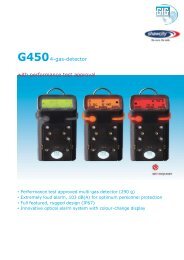
_<strong>SV</strong>AN <strong>106</strong> <strong>User</strong> MANUAL5.6 The results history loggingWhen the Logger function is chosen for the Logging Mode, the Data Logging list enables the user toprogram the history of results recording in the logger file.Depending on the Instrument Mode, theData Logging list consists of two positionsin case of Simple Mode: Logger Setup,Logger Results; or the list consists of fourto five active positions in the case ofAdvanced Mode: Logger Setup,Logger Results, Logger Trigger,Event Recording (which in turn is activewhen Event Recording position in theGeneral Settings list is also active) andMarker Setup.5.6.1 Data logger programming – Logger SetupThe Logger Setup list enables the user to edit the name of the logger file(history of results measurements or wave records) and to set other generalparameters. Depending on what Logging Mode was selected (Logger orWave) in the General Settings window the Logger Setup window hasdifferent view.When Logger mode is selected the user may also define the interval of thedata logging in a file (Logger Step). The Logger Step can be set from 100milliseconds to 1 hour.The Logger Name enables the user toname the logger file. The default name isLOG# for Logger files and &REC# forWave files. The name can be up to eightcharacters long. After pressing the , push-buttons, the special window withtext editor function is opened for editing.The edited name is accepted and saved after pressing . The special warning is displayed in case afile with the edited name already exists in the memory. The instrument waits then for a reaction of the user(any push-button should be pressed except or ).The main measurement results (cf. App. B) are calculated in the period set on in the Meas. Period position.These results can be saved in the result files in the instrument or external memory. If Meas. Period isgreater than 9 seconds, the saving can be done also by means of the Auto Save operation. If theRepetition No. is greater than one, the Auto Save operation will be performed after the period set on in theMeas. Period position. The name of the file with the main results is increased by one after each saving.When Logger Mode is switched on (On), the partial measurement results are calculated in the periodinterval set on in the Logger Step position. Up to 60 results can be logged simultaneously from all channels37
time historysignal amplitudePEAK, MAX, MIN or RMSmain resultsfiles_<strong>SV</strong>AN <strong>106</strong> <strong>User</strong> MANUALand profiles of the instrument (PEAK / P–P/ MAX / RMS / VDV) and two vectors (VEC13 and VEC46) withtime step down to 100 ms. These results are saved in one logger file. The name of the file is set in theLogger Name position. The recording in the logger’s memory is stopped after the period, which is equal toMeas. Period multiplied by Repetition No., or after pressing the push-button or after stoppingthe measurements remotely.Measurements started by push-button, ended by last repetition cycleREP. CYCLEn=1REP. CYCLEn=1REP. CYCLEn=N-1REP. CYCLEn=N0 T 2T (N-2)T(N-1)TNTtimeINTEGR. PERIODTINTEGR. PERIODTINTEGR. PERIODTINTEGR. PERIODTmeasurementsendstartAUTO SAVE AUTO SAVE AUTO SAVE AUTO SAVE@sig1.svn @sig2.svn @sigN-1.svn @sigN.svnmain resultsintegration periodfrom 0 to Tmain resultsintegration periodfrom T to 2Tmain resultsintegration periodfrom (N-2)Tto (N-1)Tmain resultsintegration periodfrom (N-1)Tto NTLOGGER: ON&logger1.svnRMS results loggedwith LOGGER STEP.Number of resultsequal NT / LS0 LS LOGGER STEPNTtimeRelations between Measurement Cycle (Integration Period) and Logger Step5.6.2 Results selection – Logger ResultsThe Logger Results list enables the userto activate the results for all channels andprofiles (Channel x Profile x) and forvectors (Vector) to be recorded in thelogger file as time history.38
_<strong>SV</strong>AN <strong>106</strong> <strong>User</strong> MANUALThe view of the Logger Results listdepends on the settings of theEnabled ChannelsandEnabled 2nd profiles parameters (path: / Measurement / Channels Setup).In Advanced Mode it is possible to definelogger results for each channel and profileindividually.Selection results for channels and profilesDepending on Instrument Mode and the Enable 2nd profiles parameterthe user may activate the results for channels and profiles (PEAK, P-P,MAX, RMS and VDV), which will be recorded to the logger file (columnLog), activate plot (column Plot) and select its colour (column Color) in thewindows with names: Channels x-y / Channels x-y Profile z / Channel x /Channel x Profile y.The VDV history will not be recorded if Wh filer is chosen in this profile.Activation / deactivation can be done by means of the , pushbuttonspressed together with . The position is changing by meansof the , and , push-buttons.The example display of Logger with twoselected results is attached.=>39
_<strong>SV</strong>AN <strong>106</strong> <strong>User</strong> MANUALSelection vectors for loggingThe Vector list enables the user to activatethe vectors (VEC13 and VEC46), which willbe recorded to the logger file, activate plotand select its color.5.6.3 Logger trigger parameters setup – Logger TriggerThe Logger Trigger position appears onlyin the advanced instrument mode (path: / Auxiliary Setup /Instrument Mode: Advanced Mode).The Logger Trigger parameters define theway the measurement results are saved inthe logger. The Logger Trigger switcheson the result logging. The logger triggering of the measurements (Enabled) can be switched onby means of the push-button.In the Logger Trigger sub-list the user may switch off or on (Enabled) thelogger triggering, determine the parameters of the triggering signal(Trigger Parameters), select the number of the results saved in the loggerbefore the fulfilment of the triggering condition (Pre) and the number of theresults saved in the logger after the fulfilment of the triggering condition(Post). If the triggering condition is fulfilled, the logger contains:the measurement results registered directly before the fulfilment of the triggering condition. Time of thisrecording can be calculated by multiplying the value set in the Pre position by the time period takenfrom the Logger Step position (path: Menu / Measurement / Data Logging / Logger Setup);all measurement results up to the moment the triggering condition disappears;the results registered directly after the moment the triggering condition disappears. Time of thisrecording can be calculated by multiplying the value set in the Post position by the time period takenfrom the Logger Step position (path: Menu / Measurement / Data Logging / Logger Setup).Pre and post trigger recordingIn the Pre/Post line the number of theresults recorded in the logger’s filebefore/after the fulfilment of the triggeringcondition can be set. This number is withinthe limit 0..20 for Pre trigger and 0..200 forPost trigger.=>40
_<strong>SV</strong>AN <strong>106</strong> <strong>User</strong> MANUALTrigger parameters settingThe position Trigger Parameters enablesthe user to define the parameters of thetriggering signal. To open this position theuser should select it and press .The Trigger position enables the user toselect the trigger type: Level -, Level +,Slope -, Slope +, Gradient - andGradient +.In each interval of the measurement, defined by Trig. Step, the triggering condition is checked and:if Level + is selected, the triggering condition is fulfilled only when Source has the greater value thandetermined by Level, otherwise the triggering condition is not fulfilled.if Level – is selected, the triggering condition is fulfilled only when Source has the lower value thanthis determined by Level, otherwise the triggering condition is not fulfilled.if Slope + is selected, the triggering condition is fulfilled only when the rising value of Source ispassing the level determined by Level.if Slope – is selected, the triggering condition is fulfilled only when the falling value of Source ispassing the level determined by Level.if Gradient + is selected, the triggering condition is fulfilled only when the signal has the greater levelthan determined by Level and the gradient of the signal is greater than determined by Gradient.Otherwise the triggering condition is not fulfilled.if Gradient - is selected, the triggering condition is fulfilled only when the signal has the lower levelthan this determined by Level and the gradient of the signal is lower than determined by Gradient.Otherwise the triggering condition is not fulfilled.Step for checking the triggeringconditionThe Trig. Step position enables the user toselect time (integration period) for conditionevaluation: equal to Logger step (path: / Measurement / Data Logging /Logger Setup), 100ms, 1.0s, and equal toMeas. Period (path: /Measurements / General Settings). IfMeas. Time is selected the triggeringconditio is checked every second and RMSis averaged from the begining of themeasurement (Meas. Time is displayed inthe right upper corner of the display rightunder the real Time Clock).41
_<strong>SV</strong>AN <strong>106</strong> <strong>User</strong> MANUALSource for triggering condition andchannel of triggering signalThe Source position enables the user toselect the type of source for triggeringcondition calculation: Vector or Profile 1.The Channel position enables the user toselect the channel of triggering source.Depending on value of the Sourceparameter, the value of Channel will bedifferent.Function for triggering condition definition and thresholdThe Result position enables the user to select the result for triggeringcondition: PEAK, P-P, MAX, MIN, RMS or VDV. When Vector is selectedas a Source the only one result is available – RMS.The Level position enables the user to select the value of threshold fortriggering condition. The level of the triggering source can be set in a rangefrom 60 dB to 200 dB or from 1.00 mm/s 2 to 10.0 km/s 2 , depending onwhat scale type was selected in the Scale position (path: / Display/ Results Scale).Speed of the triggering signal changeThis position appears when the Gradient - or Gradient + trigger arechosen. The speed of the triggering signal changes (Gradient) can be setfrom 1 dB to 100 dB range. Speed is defined as dB per Logger Step.5.6.4 Event recording setup – Event RecordingThe Event Recording position appearsonly in Advanced Mode (path: /Auxiliary Setup / Instrument Mode) andbecomes active when Event Recordingparameter in the General Settings list isswitched on.=>42
_<strong>SV</strong>AN <strong>106</strong> <strong>User</strong> MANUALThe Event Recording enables the user to activate recording of events andto set the parameters of event signal recording in the same logger file as forthe regular time results history.The Sampling Rate position displays the sampling frequency of eventrecording – 6000 Hz.When the Trigger position is selected thenevent recording will start by trigger.Trigger condition is set up in the windowopened by pressing on theTrigger Parameters position. This positionappears on the list after activating theTrigger.When Trigger On Marker is switched on then event recording will start byinitiation of one of the markers. Markers for triggering are defined in theMarkers Setup window.When Trigger and Trigger On Marker are chosen then event recording willstart when one of these triggering conditions are fulfilled.When Trigger or Trigger On Marker is chosen then additional positionsappears on the list. These positions enable the user to programmeadditional parameters of event recording.When Pre Trigger is switched on then the signal starts to record before thetriggering condition. This time length interval is defined by the value of thePre parameter of the Logger Trigger window (path: /Measurement / Data Logging).In the Rec. Limit position the user may select time of event signal recordingafter triggering. If the triggering condition appears then the signal will berecorded during the period defined in Rec. Time. The available values ofRec. Limit are: Max Length, Fixed Len. or Off.When Off is chosen then the event signal will be recorded until the memoryis full or while the trigger condition is fulfilled. When Max Length is chosenthen the signal will be recorded for the period defined by Rec. Time, butcan be stopped earlier if trigger condition is not fulfilled. When Fixed Len. ischosen then the signal will be recorded for the period defined by Rec. Time,even when the trigger condition ceases.43
_<strong>SV</strong>AN <strong>106</strong> <strong>User</strong> MANUALIn the Rec. Time position the user mayselect the time of signal recording aftertriggering occurs. If the next triggeringcondition appears then the signal will berecorded for an additional period defined byRec. Time.The Channel x positions allow the user toswitch on or off the channels to be used forevent recording.5.6.5 The marker setup – Marker SetupMarker is used to mark special events during the measurement such as not typical vibration impact and isnothing but an indication of the beginning and end of the block of logger results in which the event occurred.In case of point markers there is no start and end of the marker, but only one record in the logger file.Markers are activated in the result presentation window by pressing the arrow keys.The Marker Setup position appears only inthe advanced instrument mode (path: / Auxiliary Setup /Instrument Mode: Advanced Mode).The Marker Setup enables the user toassign a specific name for each marker anddefine markers for event recording.The specific name can be edited in thewindow that is opened by means of the, push-buttons pressed togetherwith or while the cursor is onthe Name position., и или .44
_<strong>SV</strong>AN <strong>106</strong> <strong>User</strong> MANUAL5.7 Wave recordingAll positions connected with wave recordingin the Data Logging list appear only in theadvanced instrument mode (path: /Auxiliary Setup / Instrument Mode:Advanced Mode).When the Wave function is chosen in theLogging Mode position, the Data Logginglist consists of three active positions:Logger Setup, Wave Channels andWave Trigger.=>Setting-up the Wave recorder functionThe Logger Setup list enables the user to edit the name of the logger file(history of results measurements or wave records) and to set other generalparameters.The Wave Rec. position is not active. It only indicates the fixed type ofwave recording: Continuous.The user may define the format of the wave file header (Format). Format ofthe wave file header may be PCM or Extensible.The Sampling Rate position is inactive. It indicates the fixed sampling rate: 6000Hz.Selecting the channels for WaverecordingThe Wave Channels position appears onlyin the advanced instrument mode (path: / Auxiliary Setup /Instrument Mode: Advanced Mode).The Channel x positions enable the user toselect the channels to be recorded.Wave recorder trigger setupThe Wave Trigger position appears only inthe advanced instrument mode (path: / Auxiliary Setup /Instrument Mode: Advanced Mode).The Wave Trigger enables the user toactivate and programme the wave recordertrigger.45
_<strong>SV</strong>AN <strong>106</strong> <strong>User</strong> MANUALThe Enabled position switches on/off the Wave Trigger.In the Rec. Limit position the user may select time of signal recording aftertriggering. If the triggering condition appears then the signal will be recordedduring the period defined in Rec. Time. The available values of Rec. Limitare: Max Length, Fixed Len. or Off.When Off is chosen then the event signal will be recorded until the memoryis filled or while the trigger condition is fulfilled. When Max Length ischosen then the signal will be recorded for the period defined by Rec. Time,but can be stopped earlier, if trigger condition is not fulfilled any more.When Fixed Len. is chosen then the signal will be recorded for the perioddefined by Rec. Time, even when the trigger condition ceases.In the Rec. Time position the user may select the time of event signalrecording after triggering. If next triggering condition appears then the signalwill be recorded for an additional period defined by Rec. Time.The Trigger Parameters position enablesthe user to define the parameters of thetriggering signal. To open this position andthe user should press .The Trigger Parameters window andmeaning of all positions are identical as forLogger Trigger case described above.5.8 Measure trigger parameters selection – Measure TriggerThe Measure Trigger position appearsonly in the advanced instrument mode(path: / Auxiliary Setup /Instrument Mode: Advanced Mode).The Measure Trigger sub-list enables theuser to set the parameters of measuretrigger.The Measure Trigger is a contexts sub-list in which the triggering can beswitched off or on (Trigger), when on it can be determined the source ofthe triggering signal (Source), the channel of source signal (Channel), itslevel (Level) and sometimes also the speed of changes (Gradient). If RTCis selected as trigger type, start time (RTC Start) and repetition of triggering(Repeat Every) is defined.46
_<strong>SV</strong>AN <strong>106</strong> <strong>User</strong> MANUALSwitching the triggering on and offThe triggering of the measurements (Trigger) can be switched off by means of the push-buttons.The triggering is switched on if one of its six available modes is selected: Slope +, Slope –, Level +, Level –, Grad + or RTC. If the instrument works with the switched on triggering, the appropriate icon appears on thedisplay when the instrument is waiting for triggering (triggering condition is not fulfilled). The triggeringcondition is checked every 5 miliseconds.Switching the triggering by means of measured result - Slope/Level/GradIn case when Slope + is selected, the measurement starts when the arisingresult value (Source) passes above the level determined by the Levelposition value. When Slope – is selected, the measurement starts when thefalling down result value (Source) passes below the level determined bythe Level position value.The measurement is stopped when the conditions set in theGeneral Settings sub-list are fulfilled or after pressing the push-button or after receiving the proper control code remotely.The next sources of the triggering signal are available: RMS(1), VEC46, VEC13 or External. Externalsource means that the triggering will be initiated by the positive or negative slope of the signal on theinput/output socket (I/O).When Level + or Level – is selected the triggering condition is checkedevery 5 millisecond and the measurement is recorded only when the resultvalue (Source) has the greater / lower level than that determined in theLevel position, otherwise the measurement result is skipped.The next sources of the triggering signal are available: RMS(1), VEC46 orVEC13.When the Gradient + is selected, the triggering condition is checked every5 millisecond and the measurement is recorded only when the result value(Source) has a greater level than determined in the Level position and thegradient of the signal is greater than determined in the Gradient position.Otherwise the measurement result is skipped. Only one source of thetriggering signal is available: RMS(1).Checking the triggering conditionThe triggering condition is checked every 5 millisecond. The position Trig. Step indicates this.47
_<strong>SV</strong>AN <strong>106</strong> <strong>User</strong> MANUALSelection of the triggering signalThe user can select several sources for thetrigger signal: vectors (VEC13 and VEC46),RMS of the first profile (RMS(1)) andexternal signal of the I/O socket (External)...Setting the channel of the triggering signalThe Channel parameter denotes the channel of the triggering signal.Setting the level of the triggering signalThe Level position enables the user to select the value of the threshold fortriggering condition. The level of the triggering source can be set in a rangefrom 60 dB to 200 dB or from 1.00 mm/s 2 to 10.0 km/s 2 , depending on thescale type selected in the Scale position (path: / Display /Results Scale).Setting the speed of the triggering signal changesThis position appears when the Gradient - or Gradient + trigger arechosen. The speed of change of the triggering signal (Gradient) can be setfrom 1 dB to 100 dB range. Speed is defined as dB per Logger Step.Switching the triggering by means of RTCWhen the RTC (Real Time Clock) is selected the triggering starts at thetime set up by RTC Start. The user has to press the push-buttonand the measurement will be triggered at the time selected in RTC Start.The measurement is repeated with the step selected in the Repeat Everyposition. The Repeat Every parameter can have values:Measurement Cycle or Period. If Period is selected then additionalposition RTC Period appears.48
_<strong>SV</strong>AN <strong>106</strong> <strong>User</strong> MANUAL5.9 Settings whole body measurements with the use of seat accelerometer – SEATThe SEAT window enables the user toswitch on “SEAT” measurements and toassign channels for the triaxial seataccelerometer (Seat channels) or theaccelerometer for base measurements(Base channels).5.10 The alarm trigger setting– Alarm TriggerThe Alarm Trigger position appears only inAdvanced Mode (path: /Auxiliary Setup / Instrument Mode).The Alarm Trigger position enables theuser to program the trigger, whichgenerates alarm pulse on the I/O socket, ifthe Mode parameter of theMultifunction I/O window is set toDigital Out.The Alarm Trigger window and meaning of all positions is identical as for Logger Trigger case.5.11 Programming the instrument’s internal timer – TimerThe Timer position appears only inAdvanced Mode (path: /Auxiliary Setup / Instrument Mode).The Timer enables the user to programmethe internal real time clock to act as adelayed start and stop timer. Theinstrument can be switched onautomatically up to 1 month in advance atthe pre-selected programmed time andperform the measurement with the samesettings used before the instrument wasswitched off.49
_<strong>SV</strong>AN <strong>106</strong> <strong>User</strong> MANUALSelecting the mode of the timer functionThe timer can be switched off (Off),switched on only once (Single), or switchedon many times regularly (Regular) with theperiod between two consecutivemeasurements set in the Repeat Time lineas 24 hours. It means that the instrumentwill be switched on once a day at the sametime until the user disables the timerfunction.If the instrument is switched on by means of Timer then the “clock” icon appears on the screen.Setting the day for the measurement tostartThe Start Day position determines the datefor the measurement to start. The timer canbe programmed up to one month aheadand during the date setting the current stateof the Real Time Clock is taken intoaccount. The required date can be selectedin the special window, which is opened bymeans of the , push-buttons.Setting the time for the measurement tostartThe Start Time position determines thetime for the measurement to start. Therequired hour and minute can be selectedin a special window, which is opened bymeans of the , push-buttons.5.11.1 Description of an example timer function executionThe Timer function is used to programme the instrument to switch on at thedesired time and perform the measurements with the parameters set in theMeasurement sub-list.Let us assume that the user wants to switch on the instrument on the 1 st ofJanuary, at 20:30, measure the vibration during 10 seconds without usinglogger and save the results in a file named @R1.In order to do this the user has to set the parameters of the Timer function(path: Menu / Measurement / Timer), the measurement parameters (path:Menu / Measurement / General Settings), activate the Auto Save function(path: Menu / File / Save Options), name the file (the File Name window isopened after switching on the Auto Save function) and finally – switch off50
_<strong>SV</strong>AN <strong>106</strong> <strong>User</strong> MANUALthe instrument.The instrument will be switched on the 1 st of January at 20:30 and will bewarmed up for the period of 60 seconds decrementing the counter visibleon the display by one after each second.After warming up the instrument and the pre-set Start Delay time, themeasurements will be performed for a period of ten seconds. Then, theresults will be saved in the previously named file and finally – the instrumentwill switch off.51
_<strong>SV</strong>AN <strong>106</strong> <strong>User</strong> MANUAL6. DATA AVAILABLE ON THE DISPLAY – DisplayThe Display list contains the elements thatenable the independent programming of thedisplay parameters. In order to open theDisplay list the user has to press the push-button, select the Displaytext and press .The Display list is used for setting the various parameters, which are mainly dedicated for the control of thescreen display views. The list consists of:Display ModesLogger ScaleResults ScaleScreenenables the user to select the mode of measurement results presentation;enables the user to change the scale of the history plot;enables the user to change the scale of result’s presentation;enables the user to set the brightness and t switch on/off the display screen saver.6.1 Selection of the modes of measurement results presentation - Display ModesThe Display Modes list enables the user to switch on or off the currentlyavailable modes of displaying the results of measurement. The mode of theresults presentation is related to the selection of the instrument’s function(LM, 1/1 Octave, 1/3 Octave, etc.).When all display modes in the Display Modes list are switch off only themain presentation mode with two results is available. Any attempt to switchto another mode by means of the and , push-buttons givesno results.Two results of main presentation mode=>Logger presentation mode=>52
_<strong>SV</strong>AN <strong>106</strong> <strong>User</strong> MANUAL6 Channels presentation mode=>6 Profiles presentation mode=>When all display modes in the Display Modes list are switched on they all are available and can be selectedby means of the and , push-buttons.6.1.1 Main presentation modeFields description of the two resultsviewThe main presentation mode is alwaysactive and it is not possible to switch itoff.1. Channel and Profile number.2. Function name: RMS, VDV, CRF,OVL, PEAK, P–P, MTVV.14253 63. The name of the implemented filter: Wh, Wk, Wd, Wc, Wj, Wm, Wg, Wb, Wf (for first profiles) and HP,BL Wh, BL Wk, BL Wd, BL Wc, BL Wj, BL Wm, BL Wg, BL Wb, BL Wf (for second profiles); anddetector time constant: 1.0 s.4. Elapsed time shows the current second of the measurement. The value presented there belongs to therange [1, Meas. Period].5. The value of measured function.6. Units of measured value.53
_<strong>SV</strong>AN <strong>106</strong> <strong>User</strong> MANUALChanging the active fieldsJumping between positions is made bymeans of the or push-buttons.Changing the field contentWhen Profile or Function position ischosen, then the profile number orfunction name is changed by means of the and push-buttons.Changing the presentation modeThe presentation mode is changed after pressing the or push-buttons pressed together with.When Auto Save function is active the file name is indicated in the upperscreen field.Presentation mode for all channelsThe six channels measurement result’spresentation mode (6 Channels) showssimultaneously results for six channels. If Allchannels is not enabled in theChannel Activation window (path: /Measurement / Channels Setup) the 6 Channelsmode is not active.124561. Result line for Channel 1.2. Result line for Channel 2.3. Result line for Channel 6.34. Function name: RMS, VDV, CRF, OVL, TIME,PEAK, P–P and MTVV.5. The value of measured function and units of measured value. See Appendix D for definitions.6. Elapsed time shows the current second of the measurement in the range [1, Meas. Period].54
_<strong>SV</strong>AN <strong>106</strong> <strong>User</strong> MANUALChanging the active fieldsJumping between positions is made bymeans of the , or , push-buttons.Changing the field contentWhen Channel or Function position ischosen, then the profile number orfunction name is changed by means ofthe or push-buttons togetherwith .Presentation mode for three resultsThe three profiles measurement result’spresentation mode (3 Profiles) shows results forthree profiles simultaneously.1. Line for the first result.145 62. Line for the second result.3. Line for the third result.24. Function name: RMS, VDV, CRF, OVL,TIME, PEAK, P–P and MTVV.5. File name when the Auto Save function isactive (path: / File / Save Options )36. The value of measured function and units ofmeasured value.7. Elapsed time shows the current second of themeasurement. The value presented therebelongs to the range [1, Integration Period].Changing the active fieldsJumping between positions is made bymeans of the or push-buttons.55
_<strong>SV</strong>AN <strong>106</strong> <strong>User</strong> MANUALChanging the field contentWhen Profile or Function position ischosen, then the profile number orfunction name is changed by means of the and push-buttons.Presentation mode for logger viewThe time history of results saved in the logger canbe presented in the special Logger mode. TheLogger mode can be activated or deactivated inthe Display Modes window.14561. Logger plot2. Result value for the cursor position23. Name and colour of the logged result4. Name of the logger file5. Cursor36. Cursor position.Changing the active fieldsJumping between positions is made bymeans of the or push-buttons.Changing the field contentWhen Profile or Function position ischosen, then the profile number orfunction name is changed by means of the and push-buttons.Changing the cursor positionThe user may change the cursor positionby means of the , push-buttons.The appropriate value is presented in theline below the plot. …56
_<strong>SV</strong>AN <strong>106</strong> <strong>User</strong> MANUALWhen the Logger presentation mode is switched on a combined view of thelogger plot and the result presentation is available.6.2 Setting the logger presentation parameters – Logger ScaleThe Logger Scale sub-list enables the userto change the Y-axis scale of the resulthistory plot and switch on/off the grid.Setting the scale of the loggerpresentationThree options are available for the Scaleposition: Linear, Logarithm and Log-Linear. In case of Linear the graphicalpresentation and the units are linear. Incase of Logarithm the graphicalpresentation is given in the logarithmicscale and the measurement results areexpressed in decibels (the results arerelated to the values set up in theReference Levels sub-list (path: Menu /Auxiliary Setup / Reference Levels). In caseof Log-Linear Y-scale is logarithmic, butresult units are linear.Same spectrum with different Scale is aspresented here.=>=>=>57
_<strong>SV</strong>AN <strong>106</strong> <strong>User</strong> MANUALScaling the vertical axisIf Scale is set to Logarithmic or Log-Linear then the Dynamic position enablesthe user to select the required dynamicrange scaling of the graphical presentationmode. The user can obtain double, fourtimes and eight times expansion of thevertical axis (the default vertical axiscorresponds to 80 dB, after expansion itcorresponds to 40 dB, 20 dB and 10 dB –respectively).Displays with the logger results anddifferent Dynamic ranges (80 and 20 dB)are as presented here.=>=>Switching the grid on/offThe Grid position enables the user toswitch on or off the horizontal grid lines inany graphical presentation modes.=>Switching the automatic Y-scaleadjustment on/offThe Autoscale position switches on or offthe automatic adjustment of the Y axisscale to the full display view. Theadjustment is performed automaticallyevery time the spectrum is displayed.Displays with the autoscale switched offand on are as presented here.6.3 Setting the result presentation scale – Results ScaleThe Results Scale sub-list enables theuser to change the scale in the availablemodes of the measurement resultpresentation.58
_<strong>SV</strong>AN <strong>106</strong> <strong>User</strong> MANUALThere are two options for the Scaleparameter: Linear and Logarithm. In thecase of Linear all the results are shown inlinear units. In case of Logarithm themeasurement results are expressed indecibels (the results are related to thevalues set in the Reference Level window(path: / Auxiliary Setup /Reference Levels)...6.4 Setting the display brightness and power saver- ScreenThe Screen window enables the user to setthe brightness of the display and to switch onthe screen saver.Setting the brightness of the displayThe Brightness enables the user to set theproper brightness of the display by means ofthe , push-buttons. The user canselect 20 different values of this parameter.Notice: The new value of the brightness is confirmed after each press of the or pushbuttons(new value is selected without any confirmation from the push-button).Setting the power saver functionThe saving of the internal source of the instrument’s power can be achievedby means of reducing the brightness of the screen when possible.It is possible to set the Power Saver automatically. The screen may beswitched off (Screen Off) or dimmed (Dim). When either of these options isselected, after number of seconds, defined in the line Power Saver Delay,from pressing any push-button the screen is switched off or dimmed. If ithas been set, the first press of any push-button will cause the switch-on ofthe screen. The Power Saver function may also be deactivated if theDisabled parameter is selected and the screen will stay on all the time.Setting the power saver delayThe Power Saver Delay parameter defines the delay period from last useof any push-button to enter the Power saver mode. This delay period canbe set from 5 s to 60 s.59
_<strong>SV</strong>AN <strong>106</strong> <strong>User</strong> MANUAL7. SAVING THE MEASUREMENT RESULTS – FileThe File list contains the elements that enable the user to manage the datafiles that are created and saved in the internal memory of the instrument orin the external memory (micro SD) card fitted behind the bottom cover ofthe instrument.The recording of the measurement results is an essential task for theefficient use of the instrument. All available measurement results and alsoinstrument's settings are stored as a file in the internal FLASH type memoryof the instrument or on the external micro SD Card memory.Instrument's files contain data: measurement results from Level Meter; measurement results from 1/1 Octave analysis; (available as option) measurement results from 1/3 Octave analysis; (available as option) logger results (measurement time history), wave recording (available as option), setups.Notice: Because of limited internal memory capacity of theinstrument the logger and wave files can be saved on theexternal memory only. So, if there is no SD Card connected tothe instrument there is no any possibility to create any loggerfile. In such cases the Logging position in the Measurementlist is not active. The Logging position became inactive if theinternal memory was set as a working directory (see below).Result files can be saved <strong>manual</strong>ly or automatically, Setup files are saved <strong>manual</strong>ly, Logger and Wave filesare saved automatically.Each file consists of some elements, which are the same for all kind of files: a file header; the unit and software specification; the user’s text stored together with the measurement data; the parameters and global settings; the special settings for profiles; the marker of the end of the file.The File list contains the following items:File ManagerSetup ManagerSave OptionsSetup Optionsenables the user to manage the files saved in theinstrument or on external memory card;enables the user to manage the Setup files;enables the user to set the options for themeasurement result savings;enables the user to set the options for the setupsavings.60
_<strong>SV</strong>AN <strong>106</strong> <strong>User</strong> MANUAL7.1 Saving files in the instrument’s memory or external memoryThere are two options for storing result datain the internal or external memory. Oneoption is to press the push-buttonright after the measurement performance.Another option is to create inthe File Manager window.After pressing the push-button theSave Results window appears.There are two available options for saving files: with the edited name, or with the name automaticallychanged with the name increased by one. These options can be selected in the position Auto Name. IfAuto Name is switched off (Off) the name of the saved file is as selected in the position File Name. This filename can be edited in the special window, which is opened using the push-button. When theAuto Name function is set on Number, then a file is saved with the name as displayed above, but after thelast non-numeric letter of text there will be added digit 0. If there already exists any chain of digits on the endof the file text the number that these digits create will be increased by one.The number can be changed from 0 to N. The only limitation of the N value is the length of the file name,which cannot be longer than eight characters. When such limitation is reached and the instrument cannotautomatically change the file’s name the only possibility is to use a new file name.The default name for a file is displayed when first entering to this position (after power on). The default nameconsists of the day and the month’s abbreviation and cannot exceed 8 characters.The user can skip editing the file’s name and start saving the file by pressing the push-button orreturn to the File list or measurement display by pressing .To start file editing the user has to selectthe File name position and to press or push-button. After that the specialwindow with editing function opens. Theediting process is presented on the Figureto the right.Selection of the character’s position tobe editedSelect the position of the character in theedited text using the , pushbuttons.For the current position thecharacter can be changed, position canbe deleted or inserted.61
_<strong>SV</strong>AN <strong>106</strong> <strong>User</strong> MANUALChanging the edited characterThe available ASCII characters can bechanged using the (or ) pushbutton.The subsequent digits, letters andother characters appear on the display inthe inversely displayed position after eachpress of the above mentioned pushbuttons.Position insertion, deletionThe user can delete or insert the positionin the edited text using the , push-buttons, pressed together with.The edited name is accepted and the instrument returns to theSave Results window after pressing . Pressing the push-button again saves the file in the working directory. The specialwarning is displayed if a file with the same edited name already exists in thememory. The instrument waits then for a reaction from the user (any pushbuttonshould be pressed except or ).Notice: The files can be overwritten (using of the same file name) without any warning if theReplace option is switched on (path: / File / Save Options).Saving is not possible when the instrument is measuring the signal. Themessage “Measurement in progress!” is displayed for about 3 seconds.The message “No Results To Save” is displayed after trying to execute thesave operation in the case when no measurements were performed andthere are no results to be saved. The instrument then waits for the reactionof the user (any push-button should be pressed except or )and after pressing a push-button it returns to the Save Results window.Notice: Direct access to the Save Results window is possible after pressing the and push-buttons simultaneously if the Auto Save option is switched off (path: Menu /File / Save Options). Otherwise (Auto Save option is switched on), the results are savedautomatically, after pressing these push-buttons, in the file with the incremented name.62
_<strong>SV</strong>AN <strong>106</strong> <strong>User</strong> MANUAL7.2 Managing the files saved in the internal and external memory – File ManagerThe File Manager is used for checking thecontents of the memory and performingoperations on result and logger files suchas: open, delete, copy, move, rename,create new files or catalogues anddisplaying file and catalogue information.The list of files, catalogues and memorydevices is presented in the File Managerwindow. Files are stored in catalogues,which are organised hierarchically.Catalogue names are of capital letters andhave no extensions. By pressing the push-button the window with thelist of available operations is opening forthe marked (highlighted) position.When SD Card is selected the first two positions and can be used to create new elements. When Internal memory isselected only the position is available.The list of operations on files saved in theInternal memory differs from SD Card byone position. It is not possible to renamethe files saved in the Internal memory andthus the Rename position in this list is notactive.When the memory disk is selected afterpressing the push-button the listof operations on disk appears.63
_<strong>SV</strong>AN <strong>106</strong> <strong>User</strong> MANUALIf SD Card is not installed its position in theFile Manager window is unavailable.The list of operations on the Internalmemory differs from that one for theSD Card by one position. It is not possibleto rename the Internal memory and thusRename position in this list is not active.The Internal memory can be alsodefragmented and this is performed byoperation Defragmentation.The selected catalogue can be opened intwo ways: after pressing the pushbuttonor after opening the operation list bymeans of the push-button, thenselecting the Open position and pressingthe push-button once again. TheFile Manager window is closed and theinstrument returns to the File list afterpressing .To return to the upper catalogue in thehierarchy the user has to press .The upper (highest) catalogue contains thenames and icons of memories available forfiles: SD Card and Internal. Thedescription of the memory is presentedbelow the memories list: Disk Name, Freememory and Capacity (total memoryspace).In the File Manager window files aredescribed by their file name with an extension(<strong>SV</strong>N or WAV) as well as an additional iconand measurement abbreviation (SLM, S:1/1etc.). The names in which the first character is@ come from the Auto Save function. Thetable with the description of icons is presentedat the right.CatalogueLogger fileWave fileResult fileSetup fileNew file or catalogue64
_<strong>SV</strong>AN <strong>106</strong> <strong>User</strong> MANUAL7.2.1 Setting the directory for saving files – Set Working DirectoryIt is possible to assign the catalogue forautomatic saving logger files and resultfiles. In order to do this the user shouldchoose the required catalogue and pressthe push-button. After openingthe list of operations the user should selectSet Working Directory and press again. The new catalogue namewill appear at the bottom line of the display.Starting from this moment all files will besaved in this catalogue.7.2.2 Creating new catalogue and new fileIt is possible to create a new catalogue inthe file system on SD Card. The usershould enter the catalogue in which thenew one will be created and press the push-button at the position. The suggestednew catalogue name will appear at thebottom line of the display. If a directoryalready exists there with the same namethe warning message will appear.Otherwise this operation will be performed.There is another way of saving results as afile in the internal or external memory thanpressing the push-button. This canbe done in the File Manager window bycreating new file in the file system. Toperform this function the user should enterthe catalogue in which the new file will becreated and press the pushbuttonat the position.There are two available functions: saving asetup file with the name increased by one(Auto Name=Number), and– saving asetup file with the edited name(Auto Name=Off).65
_<strong>SV</strong>AN <strong>106</strong> <strong>User</strong> MANUAL7.2.3 Deleting all files from Internal memory – Delete AllIt is possible to delete all result and/orsetup files from the instrument's memory.To do this the user should select thememory type and press the push-button. After opening the list ofoperations select the Delete All positionwith the , push-buttons and pressthe push-button again.To delete files from the Internal memorythe user has to mark the desired file typethen press the push-button. TheDelete All window with the list of file typeswill be opened. The user will be asked toconfirm the deletion of the selected filetype. Select Yes then press todelete otherwise press to continuewithout deletion.7.2.4 Merging result and setup files memory – DefragmentationThe Defragmentation option is used to make the Internal memory spacecontiguous. All new files are saved starting from the beginning of the freememory space. The memory occupied by the deleted file, assuming that thefile was not the last one, remains unused for the next files saving. After theremoving a file the memory space becomes discontinuous, with unusedparts, which cannot be utilized in the future.The situation changes after the process called defragmentation. During thisprocess the files saved in the files memory are moved in order to obtainminimum continuous occupied space.After pressing the push-button on the active Yes option, theinstrument checks whether the used result and setup files memory iscontinuous or not. If this memory is continuous, the Defragmentationoperation is not executed and the special message is displayed. Theinstrument waits for the reaction of the user (any push-button should bepressed except and ) and after pressing a push-button itreturns to the Defragmentation sub-list.66
_<strong>SV</strong>AN <strong>106</strong> <strong>User</strong> MANUALIf there are conditions to execute the Defragmentation operation thecurrent progress of defragmentation is shown on the display. Aftersuccessful defragmentation, the special message is displayed and theinstrument waits for the reaction of the user. Any push-button should bethen pressed except and . After pressing a push-button, theinstrument returns to the Defragmentation sub-list.7.2.5 Opening file/catalogue – OpenIt is possible to open file or catalogue fromthe file/catalogue list. The user shouldselect the file/catalogue and press the push-button. After opening thelist of operations select the Open positionwith the , push-buttons and press again. The effect of suchoperation for the catalogue is the same asopening the catalogue by means of the push-button.Opening the measurement file means thatthe measurement results saved in this filewill be loaded to the instrument's operationmemory and may be reviewed on thescreen.7.2.6 Deleting file/catalogue – DeleteIt is possible to delete a file or cataloguefrom the file/catalogue list. The user shouldselect the file/catalogue and press the push-button. After opening thelist of operations select the Delete positionand press the push-buttonagain.67
_<strong>SV</strong>AN <strong>106</strong> <strong>User</strong> MANUAL7.2.7 Copying file/catalogue – CopyIt is possible to copy a file or cataloguefrom the file/catalogue list in one memorytype to another or from one catalogue ofexternal memory to another catalogue inthe same memory. It is not possible to copylogger files to the Internal memory sincethis type of memory does not supportcatalogues of files.In order to perform this operation select thefile/catalogue and press the push-button. After opening the list ofoperations select the Copy position andpress the push-button again.The instrument then will propose to choosethe target catalogue for copying. Afterselection of the target catalogue the usershould press the push-button.The window with two options will appear:Copy Here and Rename.7.2.8 Moving file/catalogue – MoveIt is possible to move file or catalogue from the file/catalogue list in onememory type to another or from one catalogue of external memory toanother catalogue in the same memory. It is not possible to move loggerfiles to the Internal memory since this type of memory does not acceptsuch files.In order to perform this operation select the file/catalogue and press the push-button. After opening the list of operations select the Moveposition and press the push-button again. The instrument thenwill propose to choose the target catalogue for copying. After selection ofthe target catalogue press the push-button. The window with twooptions will appear: Move Here and Rename.7.2.9 Renaming file/catalogue – RenameIt is possible to rename a file or catalogue.In order to do this the user should selectthe file/catalogue and press the push-button. After opening the list ofoperations select the Move position andpress the push-button again.The window with text editor function willappear.68
_<strong>SV</strong>AN <strong>106</strong> <strong>User</strong> MANUAL7.2.10 Information about file/catalogue – InfoIt is possible to get information about a fileor catalogue. The user should select thefile/catalogue and press the push-button. After opening the list ofoperations select the Info position andpress the push-button again.The instrument then will display theinformation about the selectedfile/catalogue.7.3 Managing the setup files – Setup ManagerThe Setup Manager is used for checkingthe contents of the memory and operatingon Setup files such as: open, delete, copy,move, rename files, create new files anddisplay file information.In the Setup Manager window only setupfiles are displayed. Setup files haveextension <strong>SV</strong>N and icon attribute .7.3.1 Saving the setup filesThere are two options to open theSetup Manager window. One option is topress push-button when ameasurement is not being performed.Another option is to open theSetup Manager position from the Filemenu.In order to save the setup file the usershould enter the catalogue in which thenew file will be created and press the push-button at the position. Save Setup window is thenopened.69
_<strong>SV</strong>AN <strong>106</strong> <strong>User</strong> MANUALThere are two available functions: saving asetup file with the name increased by one(Auto Name=Number), and– saving asetup file with the edited name(Auto Name=Off).7.3.2 Operations on the setup filesThe Setup Manager enables the user toperform operations on the setup files in thesame way as it was described above for theFile Manager position. To perform any ofthe operations like: Open, Copy, Move,Rename, Info and Delete the user shouldchoose the file for which this operation willbe applied and press the pushbutton.The list of operations then will open.Opening the setup file means that thesettings saved in this file will be loaded tothe instrument's operation memory. So ifthe user presses the pushbuttonthe instrument will start themeasurement with the newly loadedsettings...To get information about the setup file theuser should select the file and press the push-button. After opening thelist of operations select the Info positionand press the push-buttonagain.70
_<strong>SV</strong>AN <strong>106</strong> <strong>User</strong> MANUAL7.4 Controlling data storing in the instrument’s memory - Save OptionsThe Save Options sub-list is used for theselection of the options for storing data inthe instrument's files.It is possible to replace an existing file inthe memory by a new file with the samename (Replace), to save automatically theresults of the measurements (Auto Save),to save the results with the automaticallyincremented name (Direct Save).Replacement of the existing files by the new onesThis option is used in remote mode and for the files created with the use ofAuto Save function. The result of an attempt to save a file with a name,which already exists in the memory, depends on the setting of the Replaceparameter. If the position is active then the old file will be erased and thenew file will be saved with the same name.The message is displayed that such operation is not available in case thisposition is not active – cf. the description of the Save. Otherwise, theexisting file is overwritten.Controlling the measurement results savingsUsing the Auto Save the user can set the self-saving of the measurementresults with automatic name number increment (Number) or without it (Off).This position was established in order not to waste too much memory of theinstrument when the self-saving is not necessary. The Auto Name positionappears after switching on the Auto Save function.Notice: The Auto Save function can be performed only in case when the Meas. Period value(path: Menu / Measurement / General Settings) is not less than 10 seconds. If it is less than10 seconds, the measurement results are not saved and this is indicated with the message!There is only one exception - when the Repetition Cycles number (path: Menu / Measurement/ General Settings) is equal to one, the Auto Save function is executed disregarding of thevalue of the integration period.71
_<strong>SV</strong>AN <strong>106</strong> <strong>User</strong> MANUALWhen the Meas. Period is too short for the Auto Save option or theRepetition No. is not equal to one the following message appears on thedisplay:When the Auto Save option is active, after starting the measurements by pressing the pushbuttonthe results are saved in the file with the selected name.Another measurement is started after pressing the push-button again. The measurement isstopped after the selected Meas. Cycle Time (path: Menu / Measurement / General Settings). The numbersof the next saved named files are automatically incremented by one. The same remarks are valid in thiscase as already stated in the description of the Save Next function.Edition the name of the Auto Save fileThe Auto Name enables the user to editthe name of the Auto Save file. To edit thefile name the user has to press the push-button. The text editing window isopened.Direct access to the Save functionThe Direct Save option enables the user to select the instrument’s nextoperation after simultaneously pressing the and pushbuttonsat the end of a measurement. If this option is not active, afterpressing these push-buttons, the Save window is accessed (if themeasurements are not performed). If the option is active, after pressing the and push-buttons the results are saved in the file with theautomatically incremented name.Press the and push-buttons during the execution of ameasurement causes, disregarding the option set in the Direct Saveposition, the message “Measurement in Progress” to be displayed.7.5 Options for setup files - Setup OptionsThe Setup Options sub-list is used for theselection of the options for storing setupfiles.The Save <strong>User</strong> Filters position is used forsaving the user filters together in the setupfiles.72
_<strong>SV</strong>AN <strong>106</strong> <strong>User</strong> MANUAL8. SETTINGS OF THE INSTRUMENT PARAMETERS – InstrumentThe Instrument list contains different sub-lists and positions, which aredirectly related to the settings of the hardware components of theinstrument. In order to open the Instrument list the user has to press the push-button, select the Instrument position and press .The Instrument list content depends onInstrument Mode selection from theAuxiliary Setup menu: Simple Mode orAdvanced Mode.In the Instrument list is used for setting the various parameters, which are primarily dedicated to control ofthe instrument hardware and contains the following items:KeyboardMultifunction I/OPower SupplyRTCRemote ControlTransducersUnit Labelenables the user to set the operating mode of the and the push-buttons.enables the user to select the available functionality of the I/O port.enables the user to check the power source of the instrument.enables the user to set the Real Time Clock.enables the user to activate or deactivate error confirmation function.enables the user to activate or deactivate the transducer's compensation.enables the user to check the type of the instrument, its serial number andthe current software version installed and the standards the instrumentfulfils.8.1 Selection of keyboard modes – KeyboardThe Keyboard sub-list enables the user toprogramme the operation mode of the, and pushbuttons.73
_<strong>SV</strong>AN <strong>106</strong> <strong>User</strong> MANUAL / push-button modeIn the Shift Mode position the user can choose between 2nd Fun. andDirect. When the Direct option is selected, the and pushbuttonsoperate as in the keyboard of a computer – in order to achieve thedesired result, the second push-button has to be pressed at the same timeas with /. When the 2nd Fun. option is selected the/ push-buttons operate in the sequence with the other one.This enables the user to use only one hand to operate the instrument. push-button working mode selectionIn the Start/Stop position the user can choose between Direct andWith Shift. When the Direct option is selected the instrument reacts oneach of the push-button pressing, starting or stopping themeasurements.When the With Shift option is selected the push-buttonoperates in conjunction or in a sequence with . The measurementsare started or stopped after pressing both push-buttons.8.2 Setting parameters of the I/O port - Multifunction I/OThe Multifunction I/O sub-list enables theuser to select the available functionality ofthe I/O port.Mode selection of the I/O portIn the Mode position it is possible to select the function of the instrument’ssocket named as I/O. This socket can be used as: the output of the analogue signal (Analog Out) transmitted from theinput of the instrument to its output without any digital processing (i.e.frequency filtering); the input of the digital signal used as an external trigger to start themeasurements (Digital In) in the instrument, acting in this case as a socalled “slave instrument”; the digital output (Digital Out) used for triggering another “slaveinstrument” (the instrument is acting in this case as a “masterinstrument”), or as a source of any alarm signal in the case of certaincircumstances occurred during the measurements (i.e. the level of theinput signal was higher than selected one).The more detailed description of the I/O operation is given in App. C.74
_<strong>SV</strong>AN <strong>106</strong> <strong>User</strong> MANUALSelection the channel for analogue outputThe Channel position enables the user to select which channel signal is assigned to the analogue out.Digital output function selection of the I/O socketThe Function position enables the user to set the function of the digitaloutput of the I/O instrument’s socket. The socket can be used as the sourceof the trigger pulse (Trig. Pulse) which starts the measurement in another“slave instrument” linked to the “master instrument” or as an alarm signalwhich appears there after fulfilling certain measurement conditions(Alarm Pulse).Polarisation selection of the digital output signalThe Polarisation position enables the user to select which polarisation ofthe signal (negative or positive) will be applied.Active level selection of the digital output signalThe Active Level position enables the user to select which level of thesignal should be treated as a valid one (“negative” or “positive” logic): Lowor High.Alarm duration selectionThe Hold Time position enables the user to select the minimum duration ofalarm signal.8.3 Checking the powering of the instrument – Power SupplyThe Power Supply position enables theuser to check the power source of theinstrument: internal battery condition,source and voltage of the external powersupply, and also set the battery type forchecking their condition.75
_<strong>SV</strong>AN <strong>106</strong> <strong>User</strong> MANUALThe instrument can be powered from four AA rechargeable or standardalkaline batteries or from the USB interface when its USB Device socket isconnected by means of the cable to a PC or USB power supply such as theSA 54. The view presented on the display for each powering sources isdifferent. The current battery voltage is displayed together with itsapproximate state (in the graphical form).8.4 Programming the instrument’s internal Real Time Clock – RTCThe RTC enables the user to programmethe internal Real Time Clock. This clock isdisplayed in the different places dependingon the selected presentation mode.The window is closed and the instrumentreturns to the Instrument list after pressingthe or push-button.Editing the time is performed in the special window, which is opened afterpressing the push-button. The selection of the correct parameter(hour, minute, second, and also day, month and year) is performed usingthe , push-buttons and the change of its value – using the , push-buttons pressed together with .The required date can be selected in a special window, which is openedafter pressing the , push-buttons when the Start Day text isdisplayed inversely in the Timer sub-list.In order to set data the user has to select its position by means of the , and , push button and then press to set thechosen value.8.5 Activating the remote control error confirmation - Remote ControlThe Remote Control position enables the user to activate or deactivateerror confirmation function. If Remote Control function is Enabled then theinstrument confirms warnings after 5 seconds and the user reaction is notrequired. This function is very useful when the instrument is working asremote controlled. If Remote Control function is Disabled then theinstrument waits for the user reaction. This mode is used in normal mode.76
_<strong>SV</strong>AN <strong>106</strong> <strong>User</strong> MANUAL8.6 Transducer's compensation activation – TransducersThe Transducers position enables the userto activate or deactivate the transducer'selectrical noise compensation.8.7 Checking the specification of the instrument - Unit LabelThe Unit Label enables the user to checkthe model number of the instrument, itsserial number, the current software versioninstalled in it and the relevant standards,which the instrument fulfils.The displayed text is scrolled on the displayafter pressing and .Notice: The contents of the Unit Label window should be always sent to <strong>Svantek</strong> local servicedepartment or official representative in case of any problems faced by the user during theinstrument’s normal operation in the field.77
_<strong>SV</strong>AN <strong>106</strong> <strong>User</strong> MANUAL9. AUXILIARY SETTINGS – Auxiliary SetupThe Auxiliary Setup list contains positionsdirectly related with measurements and notrelated with the hardware components ofthe instrument. In order to open theAuxiliary Setup list the user has to pressthe push-button, select theAuxiliary Setup position and press.In the Auxiliary Setup list the following items are available:Languageenables the user to select the language of the user interface.Factory Settingsenables the user to return to the default, factory settings.Instrument Lockenables the user to lock the menu and to reduce the access to the programfunctions of the instrument (function is under development).Instrument Modeenables the user to define the scope of available instrument functions andadjust accordingly the lists in some menu windows.Reference Levelsenables the user to program the user filters.<strong>User</strong> Filtersenables the user to select the Vibration units in which the results of theVibration Unitsenables the user to select the Vibration units in which the results of themeasurements are to be given.Warningsenables the user to switch the warnings on or off that can be displayedduring the normal operation of the instrument.9.4. Setting the language of the user interface – LanguageThe Language sub-list enables the user toselect the language of the user interface.For activation of the Russian version of theuser interface, a special code has to beentered.9.5. Return to the factory settings – Factory SettingsThe Factory Settings sub-list enables theuser to return to the default setup of theinstrument.The factory setup can be install also bymeans of the four and push-buttons pressed together.78
_<strong>SV</strong>AN <strong>106</strong> <strong>User</strong> MANUALDuring the clearing process the message WAIT... is displayed. Thefollowing message is displayed after return to the default settings and theinstrument waits for the user’s reaction to press any key to continue.9.6. Setting the scope of instrument's functions — Instrument ModeThe Instrument Mode sub-list enables the user to set the scope ofinstrument's available functions. There are two possible modes of theinstrument: Simple Mode and Advanced Mode. Advanced Mode definesthe full scope of available functions, while Simple Mode defines a limitedscope of available functions, excluding functions which are not so commonin use, like trigger, wave and event recording, user filters etc. Thus somemenu lists will have different view/content for different instrument modes.Below are some windows showing the differences between simple and advanced modes.79
_<strong>SV</strong>AN <strong>106</strong> <strong>User</strong> MANUAL9.7. Reference signal in vibration measurements - Reference LevelsThe Reference Levels sub-list enables theuser to set the reference level of thevibration signal. The values, which are sethere, are taken into account during thecalculations of the measurement resultsexpressed in the Logarithmic scale (withthe dB as the units).In the Acceleration position the user can set the reference level of the acceleration signal from 1 µms -2 to100 µms -2 . In the Velocity position the user can set the reference level of the velocity signal. It is possible toset this level from 1 nms -1 to 100 nms -1 .9.8. <strong>User</strong> filter setting – <strong>User</strong> FiltersThe <strong>User</strong> Filters sub-list enables the user to introduce the values of thecoefficients of the user defined frequency filters. This position is active onlyin 1/1 Octave and 1/3 Octave modes. This sub-list is described in Chapter10.80
_<strong>SV</strong>AN <strong>106</strong> <strong>User</strong> MANUAL9.9. Selection of the Vibration units - Vibration UnitsThe Vibration Units sub-list enables theuser to select the units for the Vibrationmeasurements.It is possible to select the Non-Metric units(e.g. g, ips, mil etc.) or Metric units (e.g.m/s 2 , m/s, m etc.).9.10. Warnings selection – WarningsThe Warnings sub-list enables the user toselect the messages, which could bedisplayed during the normal operation ofthe instrument.The measurement results are not saved in a fileWhen the Results Not Saved position is swithed on the special warning isdisplayed after pressing the push-button if the result of theprevious measurement was not saved in a file.The question Continue? appears with the warning message. There arethree options: Yes, No or Save. If Yes is chosen, the instrument returns tothe active mode of result presentation starting the new measurementprocess. If No is chosen, the instrument returns to the active mode ofmeasurement result’s presentation without starting the new measurementprocess. If Save option is chosen, then the measurement results are saved.The vector settings warningWhen the Vector Settings position is swithed on the special warning isdisplayed if the Mode parameter, selected in the Vector 1-3 or Vector 4-6windows, do not conformed to the standard.Confirmation of the instrument switch offWhen the Power Off position swithed on the warning message appearsafter pressing the push-button to switch off the instrument.81
_<strong>SV</strong>AN <strong>106</strong> <strong>User</strong> MANUAL10. 1/1 AND 1/3 OCTAVE ANALYSERThe instrument operates as the 1/1 Octave or 1/3 Octave analyser in a very similar way to the Level Metermode and, in addition, 1/1-octave or 1/3-octave analysis is performed in parallel with the Level Meteroperations. All 1/1-octaves (with the centre frequencies from 2 kHz down to 0.5 Hz; in base two system) and1/3-octaves (with the centre frequencies from 2.50 kHz down to 0.40 Hz; in base two system) digital passbandfilters work in real-time with the HP weighting filter (type 1 according to the IEC 61672-1 standard; thefilter characteristics are given in Appendix D) and the linear RMS detector.The results of 1/1 Octave and 1/3 Octaveanalysis (also called spectrum analysis)can be examined by the user on a displayin the Spectrum presentation mode. Theavailability of this mode can be switched onor off by the user (path: / Display /Display Modes)...1/1 Octave and 1/3 Octave spectrum for all centre frequencies of pass-band filters together with threeTotal Values measured with weighting filters selected by the user are presented in the Spectrum mode.10.1. Selection of 1/1 Octave or 1/3 Octave analysis modeIn order to select the 1/1 Octave or1/3 Octave analysis mode the user has toenter the Function list by pressing the push-button, then select theMeasurement Function text and press.Notice: It is not possible to change the current function while a measurement is taking place.In this case the instrument displays for about 2 seconds the text ”Measurement in Progress”.In order to change the current measurement function the instrument must be stopped!10.2. Setting the parameters of 1/1 Octave and 1/3 Octave analysis -The execution of 1/1 Octave or 1/3 Octave analysis depends on settings of the General Settings list:Measure Period and Repetition No.. Other parameters are set up by default: weighing filter (HP),frequency range (from 0.5 Hz up to 2 kHz for 1/1-octave analysis and from 0.40 Hz up to 2.50 kHz for 1/3-octave analysis) and measurement range (126 m/s 2 ). In every 1/1 octave or 1/3 octave pass band the RMSresult is measured.Additionally to the pass band RMS results three Total values are measured during 1/1 and 1/3 octaveanalysis. Total values parameters (weighting filter, type of integration filer for acceleration, velocity ordisplacement results and additional calibration factor) are setting up in the Total Values window (path: / Display / Spectrum Display Setup).82
_<strong>SV</strong>AN <strong>106</strong> <strong>User</strong> MANUALThe output of a selected 1/1 Octave or 1/3 Octave filter can be also used as a triggering signal for differenttrigger applications: triggering the logger, triggering the event recording, triggering the wave recording andalarms.10.3. Saving of 1/1 Octave and 1/3 Octave analysis results in the logger’s file -Logger ResultsThe RMS results from 1/1 Octave or1/3 Octave analysis can be saved in thelogger file. Spectrum saving in the loggerfile can be activated for each channel in theappropriate window (path: /Measurement / Data logging /Logger Results / 1/1 Octave or 1/3 Octave).If the None value is selected in the Channel x position then spectrum datawill not be saved in the logger file. If RMS value is selected, then RMSspectrum will be saved in the logger file for this channel.10.4. Selection of 1/1 Octave and 1/3 Octave bandpass results as triggeringsourceFor the 1/1 Octave or 1/3 Octave functions it is possible to define triggercondition for logger, event, wave and alarm triggers, based on the selectedspectrum band levels.The trigger conditions for the above applications can be programmed in thewindows: Logger Trigger, Event Recording Trigger, Wave Trigger andAlarm Trigger. In these sub-lists the user should select Spectrum in theSource position and select required central frequency of the bandpass inthe Result position.The trigger condition can be defined for the selected RMS result in theResult position calculated for 1/1 Octave filters (0.50 Hz, 1.00 Hz, 2.00 Hz,4.00 Hz, 8.00 Hz, 16.0 Hz, 31.5 Hz, 63.0 Hz, 125 Hz, 250 Hz, 500 Hz,1.00 kHz and 2.00 kHz), or 1/3 Octave filters (0.40 Hz, 0.50 Hz, 0.63 Hz,0.80 Hz, 1.00 Hz, 1.25 Hz, 1.60 Hz, 2.00 Hz, 2.50 Hz, 3.15 Hz, 4.00 Hz,5.00 Hz, 6.30 Hz, 8.00 Hz, 10.0 Hz, 12.5 Hz, 16.0 Hz, 20.0 Hz, 25.0 Hz,31.5 Hz, 40.0 Hz, 50.0 Hz, 63.0 Hz, 80.0 Hz, 100 Hz, 125 Hz, 160 Hz,200 Hz, 250 Hz, 315 Hz, 400 Hz, 500 Hz, 630 Hz, 800 Hz, 1.00 kHz,1.25 kHz, 1.60 kHz, 2.00 kHz, and 2.50 kHz), and also Total Level resultswith appropriate filters: Total 1 (HP), Total 2 (Wd), Total 3 (Bl Wd).83
_<strong>SV</strong>AN <strong>106</strong> <strong>User</strong> MANUAL10.5. Display options in 1/1 Octave and 1/3 Octave analysis modeThe Display list is used for setting thevarious parameters which are mainlydedicated for the control of the spectrumview. The following windows contain theelements that influence the presentation ofthe results of 1/1 Octave and 1/3 Octaveanalysis:Display ModesSpectrum Display SetupSpectrum ScaleSpectrum ViewMultichannel ViewTotal Valuesenables the user to switch on the spectrum presentation mode;enables the user to select options for spectrum presentation:to change the scale of the vertical axis of the graphical presentation, switchon or off the grid, switch on or off auto scale;to choose the type of the spectrum to be presented;to select how many channels will be displayed simultaneously,to select parameters for Total Values presentation.10.6. Presentation of 1/1 Octave and 1/3 Octave analysis resultsThe Single Spectrum andMultiple spectrum positions of theDisplay Modes list are accessible only for1/1 Octave and 1/3 Octave functions.When Single Spectrum mode is switchedon the measurement screen in Spectrumvisualisation mode is as shown here.=>Field description of the Spectrum view1. Channel number2. Cursor position3. Value for the cursor position4. Used averaging5. Spectrum plot6. Used weighting filter7. Type of spectrum8. Total values9. Central frequency for the cursor position4 5 61 7238984
_<strong>SV</strong>AN <strong>106</strong> <strong>User</strong> MANUALThe user may shift the Y-axis during thespectrum presentation by means of the and (or the and) push-buttons.The user may change the cursor positionby means of the , push-buttons.The frequency and appropriate value arepresented in the line below the plot....When the Multiple spectrum mode isswitched on the measurement screen in theSpectrum visualisation mode is as shownhere.=>10.7. Setting the scale of the spectrum results presentation – Spectrum ScaleThe Spectrum Scale sub-list enables theuser to change the Y-axis scale in thespectrum presentation mode and switchon/off the grid.Setting the scale of the measurementresults presentationThree options are available for the Scaleposition: Linear, Logarithm and Log-Linear. In case of Linear the graphicalpresentation and the units are linear. Incase of Logarithm the graphicalpresentation is given in the logarithmicscale and the measurement results areexpressed in decibels (the results arerelated to the values set up in the=>85
_<strong>SV</strong>AN <strong>106</strong> <strong>User</strong> MANUALReference Level sub-list (path: /Auxiliary Setup / Reference Levels). In caseof Log-Linear Y-scale is logarithmic, butresult units are linear.Same spectrum with different Scale is aspresented here.=>=>Scaling the vertical axisIf Scale is set to Logarithmic or Log-Linear then the Dynamic position enablesthe user to select the required dynamicrange scaling of the graphical presentationmode. The user can obtain double, four andeight times expansion of the vertical axis(the default vertical axis corresponds to80 dB, after expansion it corresponds to40 dB, 20 dB and 10 dB – respectively).Displays with the 1/1 Octave results anddifferent Dynamic ranges (80 and 40 dB)are as presented here.=>=>Switching the grid on/offThe Grid position enables the user toswitch on or off the horizontal grid lines forspectrum presentation.=>Switching the automatic Y-scaleadjustment on/offThe Autoscale position switches on or offthe automatic adjustment of the Y axisscale to the full display view. Theadjustment is performed automaticallyevery time the spectrum is displayed.Displays with the autoscale switched off86
_<strong>SV</strong>AN <strong>106</strong> <strong>User</strong> MANUALand on are as presented here.10.8. Setting parameters of the spectrum presentation - Spectrum ViewIn the Spectrum View window the user canprogram the screen view in theSingle spectrum and Multi spectrumpresentation modes and to set: spectrumtype to view (View), minimum andmaximum spectrum (Minimum andMaximum).In the View position the user can select thedifferent type of spectrum such as:Averaged, Instantaneous, Max or Min.=>When the Averaged or Instantaneousspectrum is selected the user canadditionally switch on the presentation ofthe Max and/or Min spectrum.=>10.9. Selection of channels for presentation – Multichannel ViewThe Multichannel View window enablesthe user to select for which channelsspectra will be viewed during multispectrum display mode and to assign aspecial color for the spectrum bars.87
_<strong>SV</strong>AN <strong>106</strong> <strong>User</strong> MANUAL10.10. Setting parameters for total values – Total ValuesThe Total Values position enables the userto program parameters for the calculation oftotal values. There are three total valuescalculated for each channel and for all threetotal values it is possible to define weightingfilter, type of signal measurement(acceleration, velocity or displacement) aswell as calibration factor. By default HP filter is denote for the first Total value. Second and thirdTotals have same filters as were set up for profiles (Prof. 1 and Prof. 2) inthe Channels window (path: / Measurement / Channels).It is also possible to select three user filters: FUSR1, FUSR2 and FUSR3.When user filter is selected, two additional positions appear: Type andCal. Factor.In the position Type the user can define the type of integration to presentthe measured signal as acceleration (ACC), velocity (VEL) or displacement(DIL).In the Cal. Factor position the user can define any additional calibrationfactor which will be applied to the calculation of Total value.The same settings can be performed for Total 2 and Total 3 values.10.11. Setting user filter coefficients for 1/1 Octave and 1/3 Octave analysis –<strong>User</strong> FiltersThe <strong>User</strong> Filters position (path: / Auxiliary Settings / <strong>User</strong> Filters)enables the user to introduce the values of the user frequency filterscoefficients. This position is active only in 1/1 Octave and 1/3 Octavemodes. The <strong>User</strong> Filters position opens the window in which the user canclear (Clear Vibration Filters) or edit (Edit Filter) the filter coefficients forselected user filter FUSR1, FUSR2 and FUSR3.88
_<strong>SV</strong>AN <strong>106</strong> <strong>User</strong> MANUALThe Clear Vibration Filters position opensthe window with a warning before deletingthe user filter coefficients. In case of apositive answer, all coefficients of theselected filter will be zeroed.The Edit Filter position opens the windowwith the table of filter coefficients. Allpositions in this table can be edited by theuser.The opened window contains the centre frequencies of the filters and their coefficients: 0.40 Hz: available values for 0.4 Hz centre frequency filter: -100.0dB ... 100.0dB 0.50 Hz: available values for 0.5 Hz centre frequency filter: -100.0dB ... 100.0dB 0.63 Hz: available values for 0.63 Hz centre frequency filter: -100.0dB ... 100.0dB 0.80 Hz: available values for 0.8 Hz centre frequency filter: -100.0dB ... 100.0dB 1.00 Hz: available values for 1Hz centre frequency filter: -100.0dB ... 100.0dB ... 2.50kHz: available values for 2.50 kHz centre frequency filter: -100.0dB ... 100.0dB89
_<strong>SV</strong>AN <strong>106</strong> <strong>User</strong> MANUAL11. DOSIMETER FUNCTIONActivation of the dose meter functionThe Dosimeter position activates ordeactivates the dose meter function. If theDosimeter function is switched on, then allchannels will be assigned for whole-body(WBV) or hand-arm (HAV) dosemeasurement.Dosimeter parameters can be setup in the HAV/WBV Dosimeter window, opened from the Measurementlist. If the Dosimeter function is switched on, then the HAV/WBV Dosimeter position in the Measurementlist will became active and DLM, D1/1 or D1/3 function abbreviations appear in the upper line.11.1. Setting parameters for dose measurements – HAV/WBV DosimeterThe HAV/WBV Dosimeter list is opened from the Measurement menu.This list enables the user to set up the parameters for human vibration dosemeasurements, like: exposure period, type of measurement (whole body orhand arm), performed in channels 1-3 and 4-6, action limits used for somestandards (U.K., Italy, Poland, France and Germany), as well as limits,defined by the user (<strong>User</strong>).Setting the measurement type for channels 1-3 and 4-6Positions 1-3 Dosimeter and 4-6 Dosimeter enable the user to set thedesired type of the measurement, performed with the use of channels 1,2,3and 4,5,6 – hand-arm (HAV) or whole-body (WBV) vibration.Setting the exposure timeThe Exposure Time position enables the user to set the desired value ofthe exposure time that is used for the calculation of the HAV/WBV Doseresults. The Exposure Time values are within the range [00h01, 24h00].90
_<strong>SV</strong>AN <strong>106</strong> <strong>User</strong> MANUALSetting the standard for dose measurementsThe Standard position enables the user to set the standards for themeasurements of the HAV/WBV Dosimeter. The available values of thisposition are U.K., Italy, Poland, France, Germany and <strong>User</strong>.Depending on the settings in the position Standard it is possible to view(U.K., Italy, Poland, French and Germany) or edit (<strong>User</strong>) limits for dosecalculation.View or edition of the limits for dosecalculationThe View Standard Limits position opensthe window with the values for the selectedstandard.When <strong>User</strong> is selected in the Standardposition then the Edit <strong>User</strong> Limits positionappears on the screen and the user can setup the required specific values.11.2. Setting parameters for channels – Channel xThe Channel x positions enable the user to set up or display parameters forthe individual channel, like input type and filters for profiles.If Dosimeter function is active the first profile filter is set by default and itcannot be changed. When second profile is switched off the filter for secondprofile doesn’t appear as a parameter in the list.When Dosimeter function is active the filters for first profiles are predefined and depend on the type ofdosimeter measurements for the channels – WBV or HAV.If WBV measurements are performed in channels 1-3 or 4-6 the filters defined for channels are as follows:Channel 1 or 4: Wd, Channel 2 or 5: Wd, Channel 3 or 6: Wk.If HAV measurements are performed in channels 1-3 or 4-6 the filters defined for channels are as follows:Channel 1 or 4: Wh, Channel 2 or 5: Wh, Channel 3 or 6: Wh.If second profile is active during Dosimeter measurements, the filter can be HP or one of BL Wd, BL Wk orBL Wh depending on what filter was predefined for the first profile of the chosen channel, according to therule described above.91
_<strong>SV</strong>AN <strong>106</strong> <strong>User</strong> MANUAL11.3. Dosimeter presentation modeThe dosimeter presentation mode isalways active when Dosimeter isswitched on.Fields description of the dosimeterview1. Channels used for dose calculation.2. Function name: Daily Exposure,AEQ,MAX(RMS),EAV Total Time, EAV Time Left,ELV Total Time, ELV Time Left.14253 63. Second field for dose results measurement.4. Elapsed time shows the current second of the measurement. The value presented there belongs to therange [1, Meas. Period].5. The value of measured function.6. The value of measured function in the second field.11.4. Calculation of hand-arm and whole-body daily results – CalculatorThe Calculator position is used to calculatethe various parameters, which arededicated to the dosimeter measurements.This position opens theVibr. Dose Calculator menu, which basedon selected files with partial(Selected Files) HA and WB daily results.The Selected Files position is used to loaddata from the files with dosimeter results. Itis possible to select up to 10 files for thecalculations. The files are marked andloaded after pressing the pushbutton.The name of this file appears in alist as it is presented here.92
_<strong>SV</strong>AN <strong>106</strong> <strong>User</strong> MANUALThe Invalid File Content message isdisplayed when the selected file does notcontain dosimeter data. The instrumentwaits for the reaction of the user bypressing any push-button except and . After that, it returns to theSelected Files list.In the Selected Files window the user canchange the content of the table.Change the fileAfter pressing the , push-buttonstogether with , the Result File list isopened. This allows the user to performsome operation with the file. Select Different FileTo select a different file the user shouldpress the push-button on thisposition, select new file and press again.Remove File/ Clear All FilesTo remove file/all files the user shouldpress the push-button on thisposition. Selected file and all files from thetable will be deleted.Add Additional FilesTo add additional files the user shouldpress the push-button on thisposition, select the new files and press again.93
_<strong>SV</strong>AN <strong>106</strong> <strong>User</strong> MANUALReplace All FilesTo replace all files the user should pressthe push-button on this position,select new files and press again.Exposure TimeThe Exp Time (Exposure Time) defines theperiod during which the measurementresults are extrapolated. The required valuecan be set in the special window, which isopened by means of the , pushbuttonspressed together with . TheExposure Time can be set from 00h00m to24h00m. The user can set the ExposureTime for each file separately.Selection of dose resultsDose results calculated with the use ofchannels 1,2,3 or 4,5,6 can be assigned forthe calculation of Dose 1 or Dose 2 results.Dose 1 or Dose 2 results will be calculatedfor HA and WB measurements based onset of appropriate selections (files).Hand-Arm daily dose resultsThe HA Daily Results position is used todisplay daily HA dose calculations for allselected files..Whole-Body daily dose resultsThe HA Daily Results position is used todisplay daily WB dose calculations for allselected files..94
_<strong>SV</strong>AN <strong>106</strong> <strong>User</strong> MANUALHand-Arm partial resultsThe HA Partial Results position is used todisplay daily HA dose results for allselected files..Whole-body partial resultsThe WB Partial Results position is used todisplay daily WB dose results for allselected files..When Simple Mode function is selected in the Instrument Mode sub-list,then Vibr. Dose Calculator list consists of the first three positions only.95