und Betriebsanleitung Automatische Brandmelder Serie 9100 Ex
und Betriebsanleitung Automatische Brandmelder Serie 9100 Ex
und Betriebsanleitung Automatische Brandmelder Serie 9100 Ex
- No tags were found...

You also want an ePaper? Increase the reach of your titles
YUMPU automatically turns print PDFs into web optimized ePapers that Google loves.
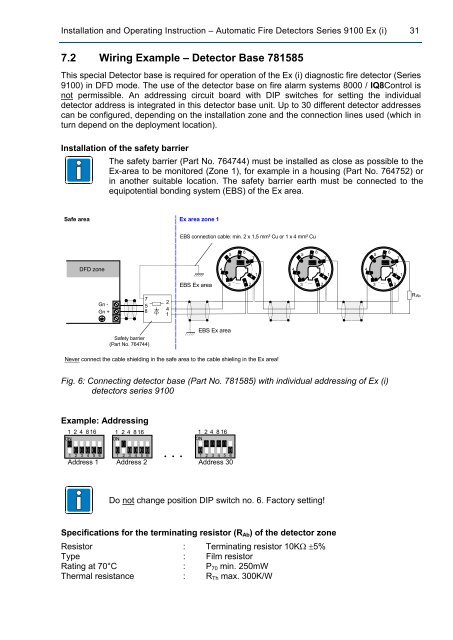
ON12 3 4 5 6ON1 2 3 4 5 6ON12 3 4 5 6Installation and Operating Instruction – Automatic Fire Detectors <strong>Serie</strong>s <strong>9100</strong> <strong>Ex</strong> (i) 317.2 Wiring <strong>Ex</strong>ample – Detector Base 781585This special Detector base is required for operation of the <strong>Ex</strong> (i) diagnostic fire detector (<strong>Serie</strong>s<strong>9100</strong>) in DFD mode. The use of the detector base on fire alarm systems 8000 / IQ8Control isnot permissible. An addressing circuit board with DIP switches for setting the individualdetector address is integrated in this detector base unit. Up to 30 different detector addressescan be configured, depending on the installation zone and the connection lines used (which inturn depend on the deployment location).Installation of the safety barrierThe safety barrier (Part No. 764744) must be installed as close as possible to the<strong>Ex</strong>-area to be monitored (Zone 1), for example in a housing (Part No. 764752) orin another suitable location. The safety barrier earth must be connected to theequipotential bonding system (EBS) of the <strong>Ex</strong> area.Safe area<strong>Ex</strong> area zone 1EBS connection cable: min. 2 x 1,5 mm² Cu or 1 x 4 mm² Cu567567567DFD zone414141EBS <strong>Ex</strong> area3 23 23 2Gn -Gn +758241RAbSafety barrier(Part No. 764744)EBS <strong>Ex</strong> areaNever connect the cable shielding in the safe area to the cable shieling in the <strong>Ex</strong> area!Fig. 6: Connecting detector base (Part No. 781585) with individual addressing of <strong>Ex</strong> (i)detectors series <strong>9100</strong><strong>Ex</strong>ample: Addressing1 2 4 816ON1 2 3 4 5 61 2 4 816ON1 2 3 4 5 6. . .1 2 4 816ON1 2 3 4 5 6Address 1 Address 2 Address 30Do not change position DIP switch no. 6. Factory setting!Specifications for the terminating resistor (R Ab ) of the detector zoneResistor : Terminating resistor 10KΩ ±5%Type : Film resistorRating at 70°C : P 70 min. 250mWThermal resistance : R Th max. 300K/W