ELECRAFT K2 - TR External Relay Driver using the 8R Line ... - N0SS
ELECRAFT K2 - TR External Relay Driver using the 8R Line ... - N0SS
ELECRAFT K2 - TR External Relay Driver using the 8R Line ... - N0SS

You also want an ePaper? Increase the reach of your titles
YUMPU automatically turns print PDFs into web optimized ePapers that Google loves.
IMPORTANT BUILDERS'S NOTICE<br />
MARCH 27, 2011<br />
This notice effects only <strong>K2</strong> <strong>External</strong> T-R <strong>Driver</strong> kits sold after 26<br />
March, 2011.<br />
Due to a change in <strong>the</strong> minimum quantity (1,000 ) I must order of <strong>the</strong> 2-pin<br />
ho<strong>using</strong>s (J2) for this kit, I have been forced to use a different connector<br />
for J2. Instead of <strong>the</strong> 2-pin ho<strong>using</strong> shown in <strong>the</strong> illustrations, you will<br />
now find a 2-pin header receptacle which has been pre-wired for your<br />
convenience.<br />
The wires used on <strong>the</strong> new J2 connector are LIGHT and DARK and<br />
should be easily identified as to <strong>the</strong>ir difference. The LIGHT wire will be<br />
ei<strong>the</strong>r white or yellow, while <strong>the</strong> dark wire will be ei<strong>the</strong>r black or green.<br />
For <strong>the</strong> sake of building this kit, always use <strong>the</strong> LIGHT-colored wire for <strong>the</strong><br />
+T-R KEYLINE and <strong>the</strong> DARK-colored wire for <strong>the</strong> GROUND.<br />
When you attach J2 to <strong>the</strong> PC board <strong>the</strong> LIGHT-colored wire will <strong>the</strong><br />
inner-most wire of <strong>the</strong> two when plugged into P2 on <strong>the</strong> PC board.<br />
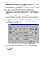
J2 - Pre-wired.<br />
Plug contact &<br />
lighter colored<br />
wire are +<strong>TR</strong>.<br />
P1<br />
J2<br />
P2<br />
R1 10k<br />
IRF610B<br />
IRF620<br />
G D S<br />
If you happen to reverse this connector, <strong>the</strong> only thing that will happen is<br />
that your amplifier will key continuously (once power has been applied to<br />
it), until you reverse <strong>the</strong> plug on P2. So no harm should come to ei<strong>the</strong>r<br />
your <strong>K2</strong> or to your amplifier.<br />
I apologize for this change in <strong>the</strong> components, but I cannot afford to order<br />
1,000 connectors in order to assemble my remaining 40 kits.<br />
Q2<br />
Q2 (alt.)<br />
Q1<br />
R3 100k
1<br />
<strong>ELECRAFT</strong> <strong>K2</strong> - T-R <strong>External</strong> <strong>Relay</strong> <strong>Driver</strong><br />
<strong>using</strong> <strong>the</strong> <strong>8R</strong> <strong>Line</strong> and J13<br />
Tom Hammond NØSS v2.4 14 MAR 2011<br />
V1.8 1/4w NØSS<br />
24SEP06<br />
P2<br />
P1<br />
<strong>K2</strong> Ext T-R Rly Drvr<br />
Bend<br />
Here<br />
<strong>8R</strong><br />
(P1-1)<br />
FIGURE 3<br />
IRF610B<br />
R2<br />
100k<br />
P1 mates with J13<br />
on <strong>K2</strong> RF board<br />
FIGURE 1 - PC BOARD<br />
As viewed from <strong>the</strong><br />
BOTTOM of <strong>the</strong> board<br />
Q2 - IRF610B or equiv.<br />
0.175-0.20 in.<br />
(4.4-5.0mm)<br />
Q1<br />
2N7000<br />
0.175-0.20 in.<br />
(4.4-5.0mm)<br />
Bend<br />
Down<br />
90°<br />
P1<br />
J2<br />
P2<br />
R1 10k<br />
FIGURE 5 - Q2 Lead Bending Detail<br />
G<br />
P1 preparation.<br />
Slide plastic<br />
carrier down<br />
on pins.<br />
3/32" (2.4mm)<br />
+6VDC<br />
(P1-8)<br />
D<br />
S<br />
GND<br />
(P1-2&4)<br />
R1<br />
10k<br />
J2 - Pre-wired.<br />
Plug contact &<br />
lighter colored<br />
wire are +<strong>TR</strong>.<br />
SCHEMATIC<br />
R3<br />
100k<br />
Q2<br />
IRF620<br />
or equiv.<br />
G<br />
D<br />
S<br />
GND<br />
(P1-2&4)<br />
Q2<br />
IRF610B<br />
IRF620<br />
G D S<br />
Q2 (alt.)<br />
P2-1<br />
P2-2<br />
Q1<br />
R3 100k<br />
FIGURE 2 - PARTS LAYOUT<br />
As viewed from <strong>the</strong> TOP<br />
of <strong>the</strong> PC board<br />
Foil side of<br />
PC board<br />
J2<br />
Open Drain Output<br />
(pulled to GND on TX)<br />
NOTE: If you do not need to<br />
be able to key voltages more<br />
than +50VDC or currents<br />
over 150mA, you may replace<br />
Q2 with Q2 (alt.) (2N7000) at<br />
<strong>the</strong> location shown below. Q2<br />
(alt.) is NOT included in this kit.<br />
Q1<br />
Q2 (alt.)<br />
2N<br />
7000<br />
S G D<br />
P1 P2<br />
FIGURE 4 P1 & P2<br />
Installation<br />
Light(er) colored wire<br />
+T-R<br />
GND<br />
FIGURE 6 - J2 Wiring<br />
Q2<br />
IRF610B<br />
IRF620<br />
G D S
RCA jack<br />
for <strong>K2</strong> T-R<br />
output<br />
BNC jack<br />
for K160RX<br />
(if installed)<br />
<strong>K2</strong> T-R <strong>Relay</strong> <strong>Driver</strong> PC board installed in a <strong>K2</strong>.<br />
<strong>K2</strong> <strong>8R</strong>-<strong>Line</strong> <strong>External</strong> Amp. T-R Control Adapter<br />
PARTS LIST<br />
Part ID Description Mouser #<br />
Q1 2N7000 MOSFET 512-2N7000<br />
Q2 IRF620 MOSFET (200VDC, 6A max.) or 511-IRF620<br />
IRF610B MOSFET (200VDC, 3,3A max.) or 512-IRF610B<br />
2N7000 MOSFET (60VDC, 200mA max.) 512-2N7000<br />
R1 10k 1/4w carbon film resistor (Brn-Blk-Org) 660-CF1/4C103J<br />
R2,R3 100k 1/4w carbon film resistor (Brn-Blk-Yel) 660-CF1/4C104J<br />
P1 8-pin header, "long post" male header 517-834-03-36<br />
J13 8-pin single-row recept., installs in <strong>K2</strong> RF-J13 517-974-01-36<br />
P2 2-pin rt-angle header 538-22-28-8020<br />
J2 2-pin ho<strong>using</strong> 538-22-01-2027<br />
Misc Crimp Terminals for 2-pin ho<strong>using</strong> (2 req.) 538-08-50-0114<br />
Misc Phono jack, panel-mount 161-1002