Magnetic and technological properties - Waasner
Magnetic and technological properties - Waasner
Magnetic and technological properties - Waasner

You also want an ePaper? Increase the reach of your titles
YUMPU automatically turns print PDFs into web optimized ePapers that Google loves.
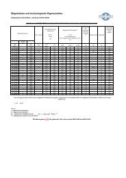
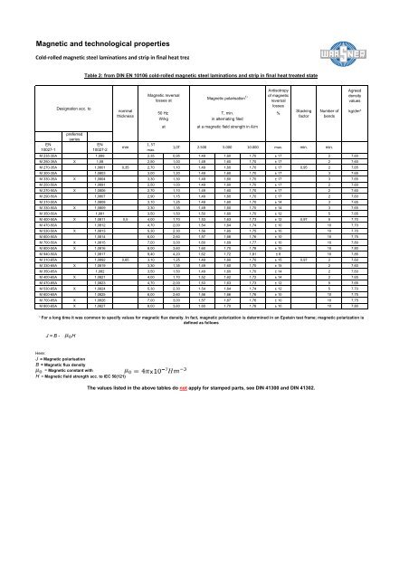
<strong>Magnetic</strong> <strong>and</strong> <strong>technological</strong> <strong>properties</strong><br />
Cold‐rolled magnetic steel laminations <strong>and</strong> strip in final heat trea<br />
Designation acc. to<br />
J = B - H<br />
nominal<br />
thickness<br />
Here:<br />
J = <strong>Magnetic</strong> polarisation<br />
B = <strong>Magnetic</strong> flux density<br />
= <strong>Magnetic</strong> constant with<br />
H = <strong>Magnetic</strong> field strength acc. to IEC 50(121)<br />
Table 2: from DIN EN 10106 cold-rolled magnetic steel laminations <strong>and</strong> strip in final heat treated state<br />
<strong>Magnetic</strong> reversal<br />
losses at<br />
50 Hz<br />
W/kg<br />
at<br />
<strong>Magnetic</strong> polarisation 1)<br />
T, min.<br />
in alternating filed<br />
at a magnetic field strength in A/m<br />
Antisotropy<br />
of magnetic<br />
reversal<br />
losses<br />
%<br />
1) For a long time it was common to specify values for magnetic flux density. In fact, magnetic polarization is determined in an Epstein test frame; magnetic polarization is<br />
defined as follows<br />
Stacking<br />
factor<br />
The values listed in the above tables do not apply for stamped parts, see DIN 41300 <strong>and</strong> DIN 41302.<br />
Number of<br />
bends<br />
preferred<br />
series<br />
EN<br />
10027-1<br />
EN<br />
10027-2<br />
mm<br />
1, 5T<br />
max.<br />
1,0T 2.500 5.000 10.000 max. min. min.<br />
M 235-35A 1,089 2,35 0,95 1,49 1,60 1,70 ± 17 2 7,60<br />
M 250-35A X 1,08 2,50 1,00 1,49 1,60 1,70 ± 17 2 7,60<br />
M 270-35A 1,0801 0,35 2,70 1,10 1,49 1,60 1,70 ± 17 0,95 2 7,65<br />
M 300-35A 1,0803 3,00 1,20 1,49 1,60 1,70 ± 17 3 7,65<br />
M 330-35A X 1,0804 3,30 1,30 1,49 1,60 1,70 ± 17 3 7,65<br />
M 250-50A 1,0891 2,50 1,00 1,49 1,60 1,70 ± 17 2 7,60<br />
M 270-50A X 1,0806 2,70 1,10 1,49 1,60 1,70 ± 17 2 7,60<br />
M 290-50A 1,0807 2,90 1,15 1,49 1,60 1,70 ± 17 2 7,60<br />
M 310-50A 1,0808 3,10 1,25 1,49 1,60 1,70 ± 14 3 7,65<br />
M 330-50A X 1,0809 3,30 1,35 1,49 1,60 1,70 ± 14 3 7,65<br />
M 350-50A 1,081 3,50 1,50 1,50 1,60 1,70 ± 12 5 7,65<br />
M 400-50A X 1,0811 0,5 4,00 1,70 1,53 1,63 1,73 ± 12 0,97 5 7,70<br />
M 470-50A 1,0812 4,70 2,00 1,54 1,64 1,74 ± 10 10 7,70<br />
M 530-50A X 1,0813 5,30 2,30 1,56 1,65 1,75 ± 10 10 7,70<br />
M 600-50A 1,0814 6,00 2,60 1,57 1,66 1,76 ± 10 10 7,75<br />
M 700-50A X 1,0815 7,00 3,00 1,60 1,69 1,77 ± 10 10 7,80<br />
M 800-50A X 1,0816 8,00 3,60 1,60 1,70 1,78 ± 10 10 7,80<br />
M 940-50A 1,0817 9,40 4,20 1,62 1,72 1,81 ± 8 10 7,85<br />
M 310-65A 1,0892 0,65 3,10 1,25 1,49 1,60 1,70 ± 15 0,97 2 7,60<br />
M 330-65A X 1,0819 3,30 1,35 1,49 1,60 1,70 ± 15 2 7,60<br />
M 350-65A 1,082 3,50 1,50 1,49 1,60 1,70 ± 14 2 7,60<br />
M 400-65A X 1,0821 4,00 1,70 1,52 1,62 1,72 ± 14 2 7,65<br />
M 470-65A 1,0823 4,70 2,00 1,53 1,63 1,73 ± 12 5 7,65<br />
M 530-65A X 1,0824 5,30 2,30 1,54 1,64 1,74 ± 12 5 7,70<br />
M 600-65A 1,0825 6,00 2,60 1,56 1,66 1,76 ± 10 10 7,75<br />
M 700-65A X 1,0826 7,00 3,00 1,57 1,67 1,76 ± 10 10 7,75<br />
M 800-65A X 1,0827 8,00 3,60 1,60 1,70 1,78 ± 10 10 7,80<br />
x<br />
Agreed<br />
density<br />
values<br />
kg/dm³
<strong>Magnetic</strong> <strong>and</strong> <strong>technological</strong> <strong>properties</strong><br />
Grain‐oriented magnetic steel laminations <strong>and</strong> strip in final heat treated<br />
Table 2 from DIN EN 10107 Grain-oriented magnetic steel laminations <strong>and</strong> strip in final heat treated state<br />
Designation acc. to<br />
J = B - H<br />
preferred<br />
series<br />
Here<br />
J = <strong>Magnetic</strong> polarisation<br />
B = <strong>Magnetic</strong> flux density<br />
= <strong>Magnetic</strong> constant with<br />
H = <strong>Magnetic</strong> field strength acc. to IEC 50(121)<br />
nominal<br />
thickness<br />
magnetic reversal losses at<br />
50Hz W/kg at<br />
magnetic<br />
polarisation 1) T,<br />
min. in alternating<br />
field at a magnetic<br />
field strength in<br />
A/m<br />
stacking factor<br />
EN<br />
10027-1<br />
EN<br />
10027-2<br />
mm<br />
1,5 T<br />
max.<br />
1,7 T<br />
max.<br />
800 min.<br />
M 127-23 S 1,0860 0,23 0,80 1,27 1,75 0,95<br />
M 140-27 S 1,0865 0,27 0,89 1,40 1,75 0,95<br />
M 150-30 S 1,0861 0,30 0,97 1,50 1,75 0,96<br />
M 165-35 S X 1,0856 0,35 1,11 1,65 1,75 0,96<br />
1) For a long time it was common to specify values for magnetic flux density. In fact, magnetic polarization is determined in an<br />
Epstein test frame; magnetic polarization is defined as follows:<br />
x<br />
The values listed in the above tables do not apply for stamped parts, see DIN 41300 <strong>and</strong> DIN 41302.
<strong>Magnetic</strong> <strong>and</strong> <strong>technological</strong> <strong>properties</strong><br />
Types of insulation for magnetic laminations<br />
The type of insulation has a great influence on the processing of magnetic laminations to form stacks, <strong>and</strong> on<br />
their behavior in a stack, here in particular during welding. As a rule, M 165-35S grain-oriented magnetic<br />
laminations has so-called Carlite insulation, while non-grain-oriented magnetic laminations may have different<br />
forms of insulation, <strong>and</strong> these can vary from manufacturer to manufacturer.<br />
Surface oxidised<br />
weldable<br />
painted<br />
thick paint<br />
Carlite<br />
(M 165-35S)<br />
Coating Seiten: 2 2 2<br />
nominal coating<br />
thickness:<br />
1,0 6 6<br />
Insulation resistance<br />
of surface:<br />
cm<br />
10<br />
Heat resistance<br />
under inerst gas<br />
o<br />
C 800 800 800<br />
Weldability sehr gut gut schlecht bedingt<br />
2 /Lamelle<br />
5 50<br />
The values specified are intended as a guide.<br />
As a rule, magnetic laminations with the above-mentioned surfaces are oil <strong>and</strong> also freon-resistant.
<strong>Magnetic</strong> <strong>and</strong> <strong>technological</strong> <strong>properties</strong><br />
Comparison of types of steel<br />
Type<br />
in EN 10106<br />
Type<br />
in DIN 46400 Part 1<br />
( issue 02.96 )<br />
( issue 04.83 )<br />
( issue 03.73 )<br />
EN 10027-1 EN 10027-2 Brief name Material no. EN 10027-1 EN 10027-2<br />
M 250-35A 1,0800 V 250-35A 1,0800<br />
M 270-35A 1,0801 V 270-35A 1,0801 V 110-35A 1,0899<br />
M 300-35A 1,0803 V 300-35A 1,0803<br />
M 330-35A 1,0804 V 330-35A 1,0804 V 130-35A 1,0898<br />
M 270-50A 1,0806 V 270-50A 1,0806<br />
M 290-50A 1,0807 V 290-50A 1,0807<br />
M 310-50A 1,0808 V 310-50A 1,0808<br />
M 330-50A 1,0809 V 330-50A 1,0809 V 135-50A 1,0897<br />
M 350-50A 1,0810 V 350-50A 1,0810 V 150-50A 1,0896<br />
M 400-50A 1,0811 V 400-50A 1,0811 V 170-50A 1,0895<br />
M 470-50A 1,0812 V 470-50A 1,0812 V 200-50A 1,0894<br />
M 530-50A 1,0813 V 530-50A 1,0813 V 230-50A 1,0893<br />
M 600-50A 1,0814 V 600-50A 1,0814 V 260-50A 1,0892<br />
M 700-50A 1,0815 V 700-50A 1,0815 V 300-50A 1,0891<br />
M 800-50A 1,0816 V 800-50A 1,0816 V 360-50A 1,0890<br />
Type<br />
in DIN 46400 Part 1
<strong>Magnetic</strong> <strong>and</strong> <strong>technological</strong> <strong>properties</strong><br />
Wire diameter<br />
The average wire diameter belonging to the selected ACu can be seen from the following tables. (For the same current density (in the primary <strong>and</strong> secondary windings) the primary<br />
wire diameter is higher than the secondary because of the higher relative primary current.)<br />
M type series<br />
42 55 65 74 85 102<br />
average wire diameter<br />
mm 0,075 0,15 0,236 0,335 0,4 0,56<br />
for selected ACuNc 2<br />
cm<br />
0,4 0,85 1,35 1,95 2,1 3,3<br />
approximate<br />
fluctuations<br />
2<br />
ACu max cm<br />
2<br />
ACu min cm<br />
0,84 1,4 2 2,7 2,8 4,2<br />
0,3 0,5 0,7 0,95 1,1 1,5<br />
EI type series, low waste<br />
92 106 130 150 170 195 231<br />
average wire diameter<br />
mm 0,45 0,6 0,9 1,12 1,7 2,24 3<br />
for selected ACuNc 2<br />
cm<br />
3,7 4,5 7,6 9,8 14 20,5 29<br />
approximate<br />
fluctuations<br />
2<br />
ACu max cm<br />
2<br />
ACu min cm<br />
4,5 5,5 11 15 19 28 39<br />
2 2,5 4 5,5 7 10 14<br />
EI type series, waste-free<br />
42 48 54 60 66 78 84 96 120 150N<br />
average wire diameter<br />
mm 0,05 0,07 0,1 0,13 0,16 0,25 0,3 0,43 0,65 1<br />
for selected ACuNc 2<br />
cm<br />
0,2 0,32 0,46 0,62 0,8 1,35 1,67 2,4 3,9 5,9<br />
approximate<br />
fluctuations<br />
2<br />
ACu max cm<br />
2<br />
ACu min cm<br />
0,42 0,59 0,84 1,06 1,3 2 2,3 3,4 4,8 7,3<br />
0,15 0,21 0,3 0,38 0,46 0,7 0,82 1,2 1,7 2,6<br />
UI, 3 UI type series<br />
30 39 48 60 75 90 102 114 132 150 168 180 210 240<br />
average wire diameter<br />
mm 0,06 0,12 0,16 0,2 0,34 0,5 0,65 0,85 1,15 1,5 1,9 2,2 3 4<br />
for selected ACuNc 2<br />
cm<br />
0,4 0,85 1,5 3 5,3 8,3 11 15 21 26 35 39 56 75<br />
approximate<br />
fluctuations<br />
2<br />
ACu max cm<br />
2<br />
ACu min cm<br />
0,84 1,9 2,55 4,5 7,8 12 16 22 31 38 49 55 76 100<br />
0,3 0,67 1 1 1,9 3 4 5,4 7,6 9,4 12,6 14 20 27