

Shop Tested Tablesaw Jigs - Tennessee Valley Woodworkers
Shop Tested Tablesaw Jigs - Tennessee Valley Woodworkers
Shop Tested Tablesaw Jigs - Tennessee Valley Woodworkers

You also want an ePaper? Increase the reach of your titles
YUMPU automatically turns print PDFs into web optimized ePapers that Google loves.
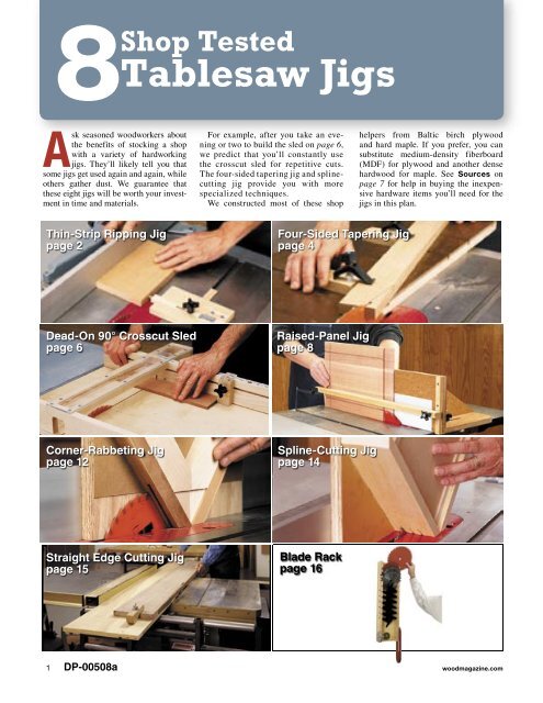
8<br />
<strong>Shop</strong> <strong>Tested</strong><br />
<strong>Tablesaw</strong> <strong>Jigs</strong><br />
Ask seasoned woodworkers about<br />
the benefits of stocking a shop<br />
with a variety of hardworking<br />
jigs. They’ll likely tell you that<br />
some jigs get used again and again, while<br />
others gather dust. We guarantee that<br />
these eight jigs will be worth your investment<br />
in time and materials.<br />
Thin-Strip Ripping Jig<br />
page 2<br />
Dead-On 90° Crosscut Sled<br />
page 6<br />
Corner-Rabbeting Jig<br />
page 12<br />
Straight Edge Cutting Jig<br />
page 15<br />
For example, after you take an evening<br />
or two to build the sled on page 6,<br />
we predict that you’ll constantly use<br />
the crosscut sled for repetitive cuts.<br />
The four-sided tapering jig and splinecutting<br />
jig provide you with more<br />
specialized techniques.<br />
We constructed most of these shop<br />
Four-Sided Tapering Jig<br />
page 4<br />
Raised-Panel Jig<br />
page 8<br />
Spline-Cutting Jig<br />
page 14<br />
Blade Rack<br />
page 16<br />
helpers from Baltic birch plywood<br />
and hard maple. If you prefer, you can<br />
substitute medium-density fiberboard<br />
(MDF) for plywood and another dense<br />
hardwood for maple. See Sources on<br />
page 7 for help in buying the inexpensive<br />
hardware items you’ll need for the<br />
jigs in this plan.<br />
1 DP-00508a<br />
woodmagazine.com
tablesaw jigs<br />
Thin-<br />
Strip<br />
Ripping<br />
Jig<br />
Here’s a safetyminded<br />
jig that will<br />
make you feel more<br />
comfortable ripping<br />
tiny pieces.<br />
Sometimes you need to rip several thin<br />
strips of wood to equal thickness to<br />
serve as edging, veneer, or bending<br />
stock. Slicing off thin stock on the<br />
fence side of the blade, however, could prove<br />
unsafe. That’s because it becomes awkward to<br />
use your blade guard and pushstick when you<br />
cut close to the fence. The solution: Run the<br />
wide portion of your workpiece between the<br />
fence and blade, cutting the strips on the side of<br />
the blade opposite the fence. You could accomplish<br />
this by measuring for each cut, but that’s<br />
tedious and inaccurate. This thin-strip ripping<br />
jig does the job safely, accurately, and quickly.<br />
A<br />
To make a cursor, scribe a line across<br />
the acrylic indicator with a sharp knife<br />
and a square. Color the scribed line with<br />
a permanent marker. Wipe off the excess<br />
ink with a cloth, leaving a fine line.<br />
Refer to Sources on page 7 for hardware<br />
for this project.<br />
First, build the jig<br />
1Cut a piece of ‡" plywood to the<br />
dimensions shown for the base on<br />
page 3. Cut a dado on the bottom side of<br />
the base for the guide bar, where shown.<br />
Now, cut the ‡" dado on the top side of<br />
the base for the sliding bar.<br />
2Cut two pieces of maple to size for<br />
the miter-slot guide bar (adjust the<br />
dimensions shown if necessary to fit<br />
your tablesaw’s slots) and the sliding<br />
B C<br />
Size your thin-strip ripping jig to suit your<br />
tablesaw, so that a 1" screw in the guide<br />
bar can contact the blade. Install a zeroclearance<br />
throat plate to prevent the<br />
sawn strip from falling into the saw.<br />
bar. Center the miter-slot guide bar in<br />
the bottom dado, and glue it in place.<br />
Drill a pair of ˇ" holes in the sliding<br />
bar, where shown, scrollsaw the material<br />
between them, and smooth the inside<br />
of the slot with a file.<br />
3Set the jig in your tablesaw’s left<br />
miter-gauge slot. Place the sliding bar<br />
in the dado with its left end flush with the<br />
base. Slide the jig forward, and mark the<br />
point where a left-leaning sawblade tooth<br />
touches the bar. Make a second mark fi"<br />
closer to the base. Remove the bar, and<br />
crosscut it at the second mark.<br />
Remove the jig before making the cut so<br />
the workpiece doesn’t bind between the<br />
rip fence and the screw head. Replace the<br />
jig in the slot without making any adjustments<br />
to set up the next cut.<br />
2 8 <strong>Shop</strong> <strong>Tested</strong> <strong>Tablesaw</strong> <strong>Jigs</strong> 2006
EXPLODED VIEW<br />
BASE<br />
4 Drill a 7 ⁄64" pilot hole in the sliding<br />
bar, centered on the end you just<br />
cut. Drive a brass screw halfway into<br />
the wood. (We used brass to avoid any<br />
chance of damaging a tablesaw blade.)<br />
You’ll turn this screw in or out to finetune<br />
your jig’s basic “zero” setting, or to<br />
adjust it for a blade of different thick-<br />
FILENAME:151<strong>Tablesaw</strong>Jig1.eps<br />
ness or Date: with 6-03 a different tooth set.<br />
From Lorna the J. bottom side of the assembly,<br />
5 drill and countersink a ‹" hole through<br />
the miter-slot guide bar and base for<br />
the machine screw that holds the plastic<br />
knob. Sand all of the wood parts to<br />
180 grit, and apply three coats of clear<br />
finish.<br />
Make a mark 1" from the left end of<br />
6 the sliding bar. Cut the first 1fi" from<br />
an inexpensive steel rule, align its left end<br />
with the mark, and attach it with epoxy.<br />
woodmagazine.com<br />
#8 x ‡" F.H. wood screw<br />
INDICATOR<br />
2"<br />
Cursor line<br />
‹ x 1fi x 2" clear acrylic<br />
6‡"<br />
4"<br />
4fi"<br />
‹" hole, countersunk<br />
on bottom side<br />
‹-20 x 1fi" F.H. machine screw<br />
Four-arm knob with ‹" insert<br />
‡" dado<br />
17⁄32" deep<br />
‹" flat washer<br />
¸" shank hole,<br />
countersunk<br />
on top<br />
‡"<br />
3"<br />
7⁄64" pilot hole<br />
fi" deep<br />
2"<br />
fi"<br />
1"<br />
‡"<br />
Œ"<br />
1fi"<br />
‡"<br />
‡" dado ¤" deep<br />
fi x ‡ x 9"<br />
#8 x 1" brass F.H. wood screw<br />
1fi"<br />
MITER-SLOT GUIDE BAR<br />
Cut a piece of ‹" acrylic to the<br />
7 dimensions shown for the indicator.<br />
Drill and countersink the two mounting<br />
holes, and scribe and mark a cursor<br />
line, as shown in Photo A. Attach<br />
the indicator to the base, and add<br />
the knob.<br />
Now, cut some strips<br />
To cut a thin strip with the jig, place<br />
its guide bar in the left-hand miter<br />
gauge slot on your tablesaw. Loosen<br />
the knob, set the cursor to zero (the<br />
bottom end of the rule), and retighten<br />
the knob. Slide the jig so that the brass<br />
screw head is beside the saw blade.<br />
Turn the screw in or out with a screwdriver<br />
until the head lightly contacts a<br />
left-leaning tooth. Pull the jig toward<br />
you, loosen the knob, set the cursor<br />
ˇ" slot<br />
9"<br />
1fi" section of steel rule<br />
SLIDING BAR<br />
for the desired strip thickness, and retighten<br />
the knob.<br />
Position your workpiece against the rip<br />
fence, and move the fence to bring the left<br />
edge of the workpiece against the screw<br />
head, as shown in Photo B. Lock the<br />
fence, set the jig out of the way, and you’re<br />
ready to cut a strip, as shown in Photo C.<br />
After completing the cut, clean up the<br />
workpiece on the jointer. Replace the jig<br />
in the slot. Then unlock the rip fence,<br />
move it to bring the jointed edge against<br />
the screw head, lock the rip fence, remove<br />
the jig, and saw another strip. Repeat<br />
the process as many times as necessary<br />
to produce all of the strips that you<br />
need for your project. ¿<br />
Written by Jim Pollock with Jeff Mertz<br />
and Kevin Boyle<br />
Illustrations: Roxanne LeMoine; Lorna Johnson<br />
3
You can taper one side of a table leg<br />
without much head-scratching,<br />
but tapering all four sides equally<br />
presents more of a challenge. With<br />
this jig, however, you can cut all four tapers<br />
without changing your setup. You simply<br />
rotate your workpiece between cuts.<br />
Locate the hold-downs to suit the length<br />
of your workpiece. (The pivot block can<br />
sit at either end of the jig.) If your tablesaw<br />
has a 10" blade, you can handle workpieces<br />
up to 2" thick.<br />
Refer to Sources on page 7 for hardware<br />
for this project.<br />
Build the jig<br />
tablesaw jigs<br />
Four-Sided<br />
Tapering Jig<br />
Here’s a slick way to taper<br />
four sides of a table leg—all<br />
with one simple jig.<br />
1For the base, cut a piece of ‡" plywood<br />
to the size shown on Drawing<br />
1, then cut a piece of ‹" hardboard to the<br />
same dimensions.<br />
2Cut fl " dadoes ‰" deep in one face<br />
of the plywood, where dimensioned.<br />
Glue the hardboard to the dadoed face<br />
with yellow glue. Now, clamp the assembly<br />
between two scraps of plywood<br />
to ensure even pressure. After the glue<br />
dries, remove the clamps, set your dado<br />
blade for a ‹"-wide cut, put an auxiliary<br />
fence on your miter gauge, and cut a slot<br />
through the hardboard, centered over each<br />
plywood dado, as shown in Photo A.<br />
3Cut a piece of maple to ‹×›×12",<br />
then cut two 3" pieces and one 3fi "<br />
piece from this blank for the guide bars.<br />
For the hold-down bases, cut a piece of<br />
‡" plywood to 1fi ×12". Cut a ‹" groove<br />
down the center of one face of this plywood,<br />
where dimensioned on the drawing.<br />
Drill two ‹" holes near opposite ends of<br />
the groove, with each hole centered in the<br />
groove and fi " from the end. Cut a 3" piece<br />
from each end to make two hold-down<br />
bases. Next, glue one guide bar piece in<br />
the groove on each hold-down base. After<br />
the glue dries, drill a ‹" hole through each<br />
assembly, using the previously drilled<br />
holes as guides.<br />
4Cut a maple blank to ‡×2×12" to<br />
make the pivot block. (We begin with<br />
an oversized piece to assure safety during<br />
the cutting process.) Cut a rabbet on one<br />
end of the blank, where shown on Drawing<br />
1a. Now, drill two holes to form the<br />
ends of the adjustment slot, remove the<br />
material between the holes with a coping<br />
saw or scrollsaw, and clean up the slot<br />
with a file. Cut a ‹" groove centered on the<br />
A B<br />
After cutting dadoes in the plywood base,<br />
glue the hardboard to the dadoed face.<br />
Mount the two outside blades of a dado<br />
set in your tablesaw, and cut slots through<br />
the hardboard centered over each dado.<br />
bottom edge of the blank. Next, drill a ‹"<br />
hole centered in the groove 2fi " from the<br />
rabbeted end. Glue in the 3fi " guide bar<br />
piece, making it flush with the rabbeted<br />
end. After the glue dries, drill a ‹" hole<br />
through the blank, using the previously<br />
drilled hole as a guide. Trim the blank to<br />
3fi " in length. Sand and finish the assembly.<br />
5Assemble the hold-downs as shown.<br />
For the pivot block, file or grind one<br />
edge of the washer flat, as shown on<br />
Drawing 1a, and then assemble the nut,<br />
screw, and washer as shown. Adjustable<br />
up or down in the slot, this screw serves<br />
as an indexing pin. Once set for a particular<br />
workpiece, it guarantees that every<br />
cut in the sequence is an equal distance<br />
from the center of the workpiece.<br />
Diagonal lines on the end of the workpiece<br />
locate the hole that fits onto the indexing<br />
pin. Draw the cutline for the final shape,<br />
and extend the lines to the edges to help<br />
you position the workpiece on the jig.<br />
4 8 <strong>Shop</strong> <strong>Tested</strong> <strong>Tablesaw</strong> <strong>Jigs</strong> 2006
1 EXPLODED VIEW<br />
1" plastic knob<br />
1" plastic knob<br />
‹" flat washer<br />
Four-arm knob<br />
with ‹" insert<br />
HOLD-DOWN<br />
fi"<br />
‹" groove<br />
‰" deep,<br />
centered<br />
‹ x 3"<br />
panhead<br />
machine screw<br />
‹" flat washer<br />
Clamp<br />
‹" nylon nut<br />
‡ x 1fi x 3" plywood<br />
‹ x › x 3"<br />
guide bar<br />
‹" holes ‹"<br />
Œ"<br />
7›"<br />
12"<br />
11›"<br />
20›"<br />
HOLD-DOWN<br />
Clamp ‹" flat washer<br />
‹" nylon nut<br />
fi"<br />
‹ x 1" brass roundhead<br />
PIVOT BLOCK<br />
machine screw,<br />
‡ x 1fi x 3" plywood nut, and washer<br />
‹" groove<br />
Ç" slot<br />
‹ x › x 3"<br />
‰" deep,<br />
guide bar<br />
centered<br />
‹" groove<br />
‹ x 3"<br />
‹" holes ‹"<br />
‰" deep, centered Œ"<br />
‹ x › x 3fi" 11›"<br />
panhead<br />
34›"<br />
7›"<br />
machine screw<br />
GUIDE BAR<br />
12"<br />
‹" slots<br />
‹" deep,<br />
centered over<br />
fl" fl" dadoes<br />
‡"<br />
woodmagazine.com<br />
fl"<br />
7‰"<br />
A<br />
11‰"<br />
B<br />
C<br />
D<br />
E<br />
N<br />
O<br />
P<br />
Q<br />
R<br />
20‰"<br />
fl"<br />
34Ø"<br />
‡"<br />
fl" dadoes<br />
‰" deep<br />
7‰"<br />
BASE<br />
11‰"<br />
‹ x 3" panhead<br />
machine screw<br />
‹ x 12 x 20‰" 36" hardboard<br />
‡ x 12 x 36" plywood<br />
F<br />
S<br />
1a PIVOT BLOCK<br />
G T<br />
3fi"<br />
H U<br />
Tap into tapering<br />
3fi" V<br />
To taper a leg, cut your workpiece I<br />
¨" rabbet to its ˇ" deep turn clockwise (as viewed from the pivot-<br />
finished length, then rip it to the square J W ing end), ¨" reclamp, and cut.<br />
dimensions that you want for the unta- ‹" This jig also serves another purpose, as<br />
X<br />
pered section at the upper end. Draw Ka<br />
line shown in Photo D. When you need to cut a<br />
on all four faces to mark where the taper Y2fi"<br />
single taper, fl" mark its start and stop points<br />
L<br />
will begin. Drill a ‹" centering hole ‹" ›" Z<br />
hole on the end and edge of your workpiece.<br />
deep at the center of the 2" bottom end, M and Remove the ‡" indexing pin from the end<br />
add cut lines to show the final dimen- block, and nest the end of the workpiece in<br />
2"<br />
¨" rabbet ˇ" deep<br />
‹"<br />
2fi"<br />
‹" hole<br />
¨"<br />
fl"<br />
‡"<br />
Ç" slot<br />
sions of that end, as shown in Photo B. the notch. Ç" Align slot the marks with the edge<br />
Draw cut lines on the face connecting of the jig, and clamp. Place your hold-downs<br />
the leg-bottom marks ‹" washer,<br />
‰" with the taper- against the workpiece. Tighten the pivot<br />
‹" groove filed to allow<br />
start marks. This helps ‹ you x › visualize x 3fi" ‰" the deep, block nut in to place, engage and make the cut. ¿<br />
final shape, and serves as GUIDE a safety BAR reminder centered the rabbet<br />
as you push the jig across the saw.<br />
Mount the leg-centering hole on the<br />
indexing pin. Slide the pivot block until<br />
the planned outside face of the leg aligns<br />
with the edge of the jig. Turn the knob to<br />
lock the pivot block in place. Now, near<br />
the upper end of the leg, align the taper-<br />
‰"<br />
‹ x › x 3fi"<br />
GUIDE BAR<br />
‹" groove<br />
‰" deep,<br />
centered<br />
‹" washer,<br />
filed to allow<br />
nut to engage<br />
the rabbet<br />
start cutline with the edge of the jig. Slide<br />
3a PIVOT BLOCK<br />
the hold-down blocks against the leg, and<br />
tighten the nylon nut on each one to set the<br />
block’s FILENAME:151<strong>Tablesaw</strong>Jig2.eps<br />
position. Tighten the top knob on<br />
each Date: hold-down 6-03 to clamp the leg in place.<br />
Lorna J.<br />
Raise the saw blade ‹" above the leg.<br />
Butt the jig to the fence, move the fence<br />
until the saw blade just clears the left<br />
FILENAME:151<strong>Tablesaw</strong>Jig2.eps<br />
Date: 6-03<br />
Lorna J.<br />
side of the jig, and then make the cut, as C D<br />
shown in Photo C. To make each of the Hold the taper jig tightly against the<br />
The width and adjustability of the taper<br />
three remaining cuts, loosen the holddown<br />
knobs, rotate the leg one-quarter<br />
tablesaw rip fence as you cut. Before<br />
starting each pass, make certain that<br />
your left hand is well away from the line.<br />
jig allow you to handle a wide range of<br />
angle cuts. Here, with the jig flipped endfor-end,<br />
we’re shaping a simple leg.<br />
5<br />
20›"<br />
fl"<br />
34Ø
tablesaw jigs<br />
Dead-On 90°<br />
Crosscut Sled<br />
When you build this sled, your<br />
accuracy and efficiency at the<br />
tablesaw will soar.<br />
A<br />
reliable tablesaw miter gauge<br />
handles a lot of crosscutting<br />
tasks, but not all. It rides in just<br />
one slot, and supports the workpiece<br />
on just one side of the blade, allowing<br />
for slop. This problem disappears,<br />
however, with an accurate crosscut sled.<br />
Our design is both inexpensive and simple<br />
to build. Plus, it includes reliable,<br />
adjustable stops for repeatable cuts. From<br />
the moment you put this jig to use at your<br />
tablesaw, you’ll discover that making<br />
right-angle cuts is easier and safer.<br />
Build a real workhorse<br />
1Select a flat piece of ‡" plywood, and<br />
cut the platform to the dimensions<br />
shown on Drawing 1.<br />
2Cut two fi×3×30" maple pieces for the<br />
fence, and cut a fl " groove ‰" deep<br />
in the face of one piece, where shown<br />
on Drawing 1a. Glue the two blanks<br />
together, keeping the edges flush and the<br />
Two pennies shim the miter-slot guide<br />
bars slightly above the tablesaw surface.<br />
Place a couple of these stacks in each<br />
miter-gauge slot, and set the bars on top.<br />
groove on the interior of the lamination. of the blade, and lower the blade below<br />
After the glue dries, cut a ‹" groove cen- the table’s surface. (Note: Make sure your<br />
tered on the fl" groove. Then, cut a rabbet fence is parallel to the miter gauge slot<br />
along the front of the bottom edge and a before proceeding.) Apply double-faced<br />
fi " groove centered along the top edge.<br />
3From ‡" maple, cut the blade guard<br />
sides and end. Glue and screw the end<br />
tape to the top of each guide bar, and attach<br />
the bars to the platform, as shown in<br />
Photos A and B. Remove the assembly<br />
to the sides. Now, screw the blade guard from the saw, and permanently attach the<br />
to the fence, where shown on Drawing 1.<br />
4Cut the front rail from ‡" maple. Use<br />
a jigsaw to cut a notch, where shown,<br />
bars with screws.<br />
7Cut a piece for the stopblock, and cut<br />
a dado in the back, where shown. Cut<br />
for the blade to pass through. Attach the a guide bar, and glue it into the dado.<br />
front rail and the fence to the platform Drill a shank hole through the block and<br />
with screws.<br />
5Cut, sand, and finish two top blade<br />
guard supports. Using a fine-toothed<br />
bar, where shown. Now, cut a piece of ‹"<br />
acrylic plastic to size for the stopblock indicator.<br />
See Drawing 1b. Drill, saw, and<br />
tablesaw blade, cut a piece of ‹" clear file smooth the slot, where shown. Make<br />
acrylic to size for the blade guard cover.<br />
Attach the cover to the supports and the<br />
front rail.<br />
6From ‡" maple stock, cut two strips<br />
to serve as miter-slot guide bars. Set<br />
a cursor line, as shown.<br />
8Remove the top blade guard, sand the<br />
jig, and apply three coats of finish.<br />
Reattach the blade guard, assemble and install<br />
the stopblock, place the crosscut sled<br />
your tablesaw rip fence 8¤" to the right on your tablesaw, and make a cut from<br />
A B C<br />
6<br />
Keeping the right end of the platform against<br />
the rip fence, set the sled assembly on<br />
the guides. Press down firmly to stick the<br />
bars to the platform.<br />
Hold the workpiece firmly against the<br />
fence as you make a cut. Keep your hands<br />
outside the blade guard, and don’t cut<br />
through its end.<br />
8 <strong>Shop</strong> <strong>Tested</strong> <strong>Tablesaw</strong> <strong>Jigs</strong> 2006
N<br />
O<br />
P<br />
Q<br />
R<br />
S<br />
T<br />
U<br />
V<br />
W<br />
X<br />
Y<br />
Z<br />
A<br />
B<br />
C<br />
D<br />
E<br />
F<br />
G<br />
H<br />
I<br />
J<br />
K<br />
L<br />
M<br />
N<br />
O<br />
P<br />
Q<br />
R<br />
S<br />
T<br />
U<br />
V<br />
W<br />
X<br />
Y<br />
Z<br />
1 EXPLODED VIEW<br />
woodmagazine.com<br />
#8 x ‡" F.H.<br />
wood screw<br />
#8 x ‡" F.H.<br />
wood screw<br />
#8 x ‡"<br />
TOP<br />
F.H.<br />
BLADE GUARD<br />
wood screw<br />
TOP BLADE GUARD<br />
¤" shank hole,<br />
countersunk<br />
TOP BLADE GUARD<br />
¤" shank hole,<br />
countersunk<br />
¤" shank hole,<br />
countersunk<br />
7 ⁄64" pilot hole<br />
‡"<br />
7⁄64" pilot hole<br />
‡"<br />
6¨"<br />
‹ x 3‹ x<br />
30"<br />
‡ x ‡ x 16‹" clear ac<br />
supports<br />
7 6¨"<br />
‹ x 3‹ x 22‡"<br />
‡"<br />
30"<br />
⁄64" pilot hole<br />
‡ x ‡ x 16‹" clear acrylic<br />
2" supports<br />
FRONT RAIL<br />
6¨"<br />
‹ x 3‹ x 22‡"<br />
2" 30"<br />
‡ x ‡ x 16‹" clear acrylic<br />
FRONT RAIL<br />
7›" ‡ x 18 x 30"<br />
supports<br />
2"<br />
plywood<br />
1fl"<br />
6¨"<br />
FRONT RAIL<br />
7›" ‡ x 18 x 30"<br />
#8 x 1fi" F.H.<br />
plywood<br />
wood screw<br />
1fl"<br />
6¨"<br />
‹ x 1 x 1‡" 7›" #8 x 1fi"<br />
8¤" ‡<br />
F.H.<br />
x 18 x 30"<br />
clear acrylic wood screw<br />
‹ x 1 x 1‡"<br />
plywood<br />
1fl"<br />
6¨"<br />
8¤"<br />
#8 x 1fi" F.H. BLADE GUARD ‡"<br />
clear 3" acrylic<br />
wood screw ‡"<br />
#8 x 1fi" F.H.<br />
3"<br />
#6 x 1" roundhead ‹ x 1 x 1‡" 8¤"<br />
BLADE<br />
wood screw<br />
wood clear screwacrylic<br />
ˇ" holes<br />
#6 x 1" roundhead<br />
‡"<br />
wood screw<br />
3"<br />
ˇ" holes<br />
‹" hexhead bolt<br />
#6 x 1" roundhead<br />
1fi" long<br />
‹" hexhead bolt<br />
wood screw 1fi" long ˇ" holes<br />
3‡"<br />
‹" hexhead bolt<br />
3"<br />
3‡"<br />
Four-arm knob<br />
3‡"<br />
1fi" long<br />
with ‹" insert<br />
3"<br />
Self-adhesive<br />
Four-arm knob<br />
Fence<br />
measuring rule<br />
3‡"<br />
STOPBLOCK<br />
3‡"<br />
with ‹" insert<br />
Self-adhesive<br />
Four-arm knob<br />
Fence<br />
measuring rule 3"<br />
STOPBLOCK<br />
Self-adhesive 4‡"<br />
with ‹" insert<br />
1 x 3 x 30"<br />
PLATFORM<br />
Fence<br />
measuring ruleˇ<br />
x 3‹" ‡ x 18"<br />
STOPBLOCK<br />
1 x 3 x 30"<br />
miter-slot guide bars 4‡"<br />
PLATFORM<br />
ˇ x ‡ x 18"<br />
‡ x 1‹ x 2Í"<br />
miter-slot guide bars<br />
stopblock<br />
‡ x 1‹ x 2Í"<br />
‹ x fi x 1‹" 1 x 3 x 30"<br />
PLATFORM<br />
ˇ x ‡ x 18"<br />
stopblock<br />
guide bar<br />
‹ x fi x 1‹"<br />
miter-slot guide bars<br />
guide ‡ bar x 1‹ x 2Í"<br />
#8 x 1fi" stopblock F.H.<br />
‹" dado ‹" deep<br />
wood screw<br />
‹ x Œ" fi from x 1‹" top edge<br />
#8 x 1fi" F.H.<br />
‹" dado ‹" deep<br />
guide bar<br />
#8 x fi" F.H. wood screw<br />
wood screw<br />
Œ" from top edge<br />
#8 x fi" F.H. wood screw<br />
#8 x 1fi" F.H.<br />
‹" dado ‹" deep<br />
wood screw<br />
Œ" from top edge<br />
the front edge through the fence. Use a<br />
#8 x fi" F.H. wood screw<br />
rule to set the stopblock 4" from the kerf.<br />
Mark the center of the stopblock on its top<br />
end, align the 4" line on the self-adhesive 1a FENCE SECTION VIEW 1b INDICATOR DETAIL 1‡"<br />
measuring tape with that mark, and attach<br />
1‡"<br />
the tape in the fence groove. Use tin snips<br />
fi" groove „" deep<br />
Á" ¤ x fi" slot<br />
(to fit measuring rule)<br />
to cut off the portion of the 1‡"<br />
fi" groove tape extend- „" deep<br />
Á" ¤ x fi" slot<br />
fi"<br />
1"<br />
ing beyond the left end of (to the fit fence. measuring Place rule)<br />
fi" groove „" deep fi"<br />
1"<br />
the indicator on the stopblock, align the<br />
¤ x fi" slot<br />
(to fit measuring Œ" rule) Ø"<br />
Á"<br />
cursor with the tape’s 4" line, and attach<br />
fl"<br />
fi" ›"<br />
1"<br />
Œ" Ø"<br />
the indicator to the block with a screw.<br />
‹"<br />
Score a line on the acrylic with a knife,<br />
fl"<br />
›"<br />
‹"<br />
‹" Œ" groove Ø"<br />
and color it with a permanent marker.<br />
Score a line on the acrylic with a knife,<br />
ˇ" deep fl" fl" groove<br />
›"<br />
Now, let’s go sledding<br />
‹" groove<br />
and color it with a permanent marker.<br />
ˇ" deep<br />
‹"<br />
‰" deep<br />
If a workpiece fits between the fence fl" groove<br />
Score a line on the acrylic with a knife,<br />
¤" rabbet<br />
‰" deep ‹" groove<br />
and color it with a permanent marker.<br />
and the front rail, you can cut it on your<br />
¤" deep<br />
¤" rabbet<br />
ˇ" deep<br />
fl" groove fi"<br />
crosscut sled, as shown ¤" in deep Photo C. Use<br />
‰" deep<br />
the stopblock to cut multiple pieces fi" to ¤" rabbet<br />
the same length, provided that length falls ¤" deep<br />
Sources fi"<br />
within the stopblock’s range. Remove the For the jigs on pages 2–8, we used these Sources:<br />
stopblock when cutting pieces that extend Stainless steel rule no. 06K20.06, 1¼" four-arm plastic<br />
beyond that range. When you install a knob no. 00M55.30. Call Lee <strong>Valley</strong> at 800/871-8158, or<br />
FILENAME:151<strong>Tablesaw</strong>Jig3.eps<br />
blade of a different thickness Date: or 6-03 with go to leevalley.com.<br />
FILENAME:151<strong>Tablesaw</strong>Jig3.eps<br />
a different tooth set than the one Lorna used J. to<br />
Date: 6-03<br />
Hold-down no. 142398 (bolt and knob); self-<br />
Lorna calibrate J. your stopblock, FILENAME:151<strong>Tablesaw</strong>Jig3.eps<br />
check the set- adhesive rule, no. 08Y42. Call Woodcraft at 800/225ting<br />
with a rule, and adjust Date: the 6-03 cursor. ¿ 1153, or go to woodcraft.com.<br />
Lorna J.<br />
7
tablesaw jigs<br />
Raised-<br />
Panel Jig<br />
With this one jig,<br />
you can build three<br />
popular styles of<br />
door panels for your<br />
next cabinet project.<br />
Raised panels have long been a sign<br />
of fine craftsmanship—perhaps<br />
because they appear difficult to<br />
make. But as you’ll see here, that<br />
need not be the case. On page 10, we’ll<br />
show you a simple method for using this<br />
jig to cut panels with a tablesaw.<br />
Combine scrap material with a few<br />
hardware items and you’ll have a jig destined<br />
for a lifetime of service. See page<br />
7, for a hardware source for the knobs.<br />
Start with the basics<br />
1Cut two pieces of ‡" MDF to the<br />
dimensions in the Materials List<br />
to make the upright (A) and base (B).<br />
Scrollsaw or bandsaw the 1fi" radii on<br />
the two corners of (B), cutting outside the<br />
line. Then sand to the line.<br />
2Using your dado blade, cut two ‡"<br />
dadoes ‹" deep in the top of the base,<br />
where shown on Drawing 1.<br />
3After adding an auxiliary fence to your<br />
saw tablesaw rip fence, cut a rabbet<br />
‡" wide and ‹" deep along the bottom<br />
edge of the upright (A), where shown on<br />
Drawing 1.<br />
4Next, drill ˇ" holes in the upright<br />
(A) and at the ends of the slot locations<br />
in the base. Lay out the sides of the<br />
slots, and scrollsaw them to shape with a<br />
#12 blade. Cut two braces (C), as dimensioned<br />
on Drawing 2.<br />
5Drill ¸" pilot holes, and then glue<br />
and screw the jig together using<br />
#8×1fi" brass screws, where shown.<br />
Tip: Use brass screws anytime your jig’s<br />
screw holes are close to the saw blade.<br />
8 8 <strong>Shop</strong> <strong>Tested</strong> <strong>Tablesaw</strong> <strong>Jigs</strong> 2006
nel 2.eps<br />
Now, add the extras<br />
1 A<br />
Cut the guide strip (D) to fit your<br />
miter-gauge N slot in depth and width.<br />
Trim the piece to 28" long, and drill coun-<br />
B O<br />
tersunk ‹" holes centered on the strip 3"<br />
from C Peach<br />
end. Attach 2 SLED the PARTS guide strip VIEW to<br />
the D base Q using the hardware shown.<br />
Cut the upright stops (E) to size, and<br />
2 E drill R the hole and counterbore 1›" hole,<br />
where S shown on Drawing 2. Secure the<br />
F F CLAMPING BAR<br />
stops 1" to the ends of upright (A).<br />
G T<br />
29"<br />
H U<br />
1 PARTS VIEW<br />
V<br />
I<br />
J W 1"<br />
F CLAMPING BAR<br />
X<br />
K<br />
Y<br />
L R=1fi"<br />
Z<br />
M<br />
ˇ" slot<br />
5"<br />
R=1fi"<br />
1¤"<br />
2 SLED PARTS VIEW<br />
29"<br />
1›"<br />
28"<br />
B<br />
BASE<br />
‡" dadoes<br />
‹" deep<br />
28"<br />
R=1fi"<br />
Cut the clamping bar (F) to size, and<br />
3 drill ˇ" holes, where ˇ" slotshown.<br />
Lay<br />
out and shape the clamping bar curve, as<br />
28"<br />
Remove the hardware and the clamp-<br />
5 ing bar Band<br />
guide strip, and sand all<br />
parts to 150 BASEgrit.<br />
Now apply two coats of<br />
shown on Drawing 1, using a bandsaw.<br />
Sand smooth.<br />
5"<br />
Next, attach the 1¤" clamping bar to<br />
4 the jig using the hardware shown.<br />
3"<br />
Tip: If you have trouble finding extra-long<br />
4fi"<br />
ˇ" machine hole screws, cut two pieces of allthread.<br />
Then secure the four-arm knobs<br />
1‹"<br />
to the screws using 5-minute epoxy.<br />
finish, sanding between coats 11fi" with 180-<br />
‡" dadoes<br />
grit ‹" abrasive. deep<br />
Cut a piece of adhesive-backed<br />
6 120-grit sandpaper, and apply it to<br />
3"<br />
the jig face, as shown on Drawing 1.<br />
4fi"<br />
Then, reassemble the jig. ¿<br />
1"<br />
ˇ" hole<br />
1‹"<br />
fi"<br />
ˇ"<br />
4fi" ‡" dadoes<br />
‹" deep<br />
Location of part<br />
on front face<br />
E 4fi" ¤"<br />
1"<br />
hole<br />
A<br />
3 PANEL CUTTING SLED<br />
EXPLODED VIEW 3"<br />
UPRIGHT<br />
(Back face shown)<br />
8"<br />
11fi"<br />
ˇ" slot 3"<br />
4fi"<br />
B<br />
BASE<br />
3"<br />
4fi"<br />
5"<br />
2 EXPLODED 1¤" VIEW<br />
‡" dadoes<br />
‹" deep<br />
11fi"<br />
3"<br />
3" 1‹"<br />
4fi" 4fi"<br />
fi" 4fi" ‡" dadoesCurve<br />
Location on this of edge part E 4fi" ¤"<br />
‹-20 x 4fi" F.H. ‹" deep on front face<br />
1›"<br />
machine<br />
ˇ"<br />
screw<br />
‡"<br />
hole<br />
Four-arm ˇ" Ahole<br />
knob UPRIGHT<br />
29" 8"<br />
(Back face Fshown)<br />
3"<br />
fi" 4fi" ‡" dadoes Location FILENAME:164 of part<br />
#8 x<br />
E<br />
1" brass<br />
Panel 4fi" 2.eps ¤"<br />
‡" rabbet‹"<br />
deepLocation<br />
on Date: front of 4 4-05 x face<br />
F.H. wood screw<br />
24" adhesive-<br />
‹" flat ˇ" washer ‹" deep backed Lorna 120-grit J.<br />
Compression<br />
sandpaper<br />
hole 1"<br />
A<br />
on front face<br />
28" spring<br />
UPRIGHT‹"<br />
flat washer 8" E<br />
1"<br />
4 x 24" adhesivebacked<br />
120-grit<br />
sandpaper<br />
1"<br />
3"<br />
3"<br />
(Back face shown)<br />
fl" counterbore ‹" deep with a<br />
ˇ" hole centered inside<br />
‡"<br />
‡" rabbet Location of 4 x 24" adhesive-<br />
Materials ‹" List deep backed 120-grit sandpaper ‹-20 knife thread insert<br />
FINISHED SIZE<br />
on front face<br />
Part T W L 28" Matl. Qty.<br />
‡" rabbet ‹" deep<br />
ˇ"<br />
slot<br />
A upright ‡" 8" 28" MDF 1<br />
B base ‡" 11fi" 28" MDF 1<br />
C braces ‡" 7fi" 11‹" MDF 2<br />
D guide strip ›" ‡" 28" M 1<br />
E upright stops ›" ‡" 8" M 2<br />
F clamping bar ‡" 1›" 29" M 1<br />
Materials key: MDF–medium-density fiberboard,<br />
M–maple.<br />
Supplies: #8×1½", #8×1" brass flathead wood screws;<br />
‹-20×2" (2), ‹-20×4fi" flathead machine screws (2);<br />
‹-20 four-arm knobs (4); ‹" flat washers (8); 1fi×›"<br />
compression springs (2); ‹-20 knife thread insert (2);<br />
4" adhesive-backed 120-grit sandpaper.<br />
‡" rabbet<br />
‹" deep<br />
Four-arm<br />
knob<br />
Location of 4 x 24" adhesivebacked<br />
120-grit sandpaper<br />
on front face<br />
28"<br />
A<br />
UPRIGHT<br />
woodmagazine.com 9<br />
anel 2.eps<br />
‡"<br />
‹-20 x 2" F.H. machine screw<br />
3"<br />
C<br />
‡"<br />
7fi"<br />
#8 x 1fi" brass<br />
F.H. wood screw<br />
D<br />
E<br />
fi"<br />
B<br />
BASE<br />
28"<br />
C<br />
BRACE<br />
11‹"<br />
fi"<br />
¸"<br />
pilot hole<br />
‡" dado<br />
‹" deep<br />
¸"<br />
pilot hole<br />
‹" holes, countersunk<br />
on bottom face
A<br />
B<br />
C<br />
D<br />
E<br />
F<br />
G<br />
H<br />
I<br />
J<br />
K<br />
L<br />
M<br />
N<br />
O<br />
P<br />
Q<br />
R<br />
S<br />
T<br />
U<br />
V<br />
W<br />
X<br />
Y<br />
Z<br />
How to Cut<br />
Custom Raised Panels<br />
1 PANEL STYLES<br />
Cut raised panels<br />
with a tablesaw<br />
For the woodworker who doesn’t have a<br />
router table or the budget for expensive<br />
raised-panel bits, cutting raised panels<br />
on the tablesaw is an effective alternative.<br />
This method does have one drawback:<br />
You’ll need to invest time and elbow grease<br />
into finish-sanding the panel bevels.<br />
To solve the challenge of supporting<br />
panels safely while cutting bevels, build<br />
the panel-cutting jig shown on page 8.<br />
Prepare the panels<br />
Before cutting the door panels to size,<br />
match the wood tones and arrange the grain<br />
patterns for best appearance. For example,<br />
center the cathedral (inverse V) pattern on<br />
narrow, single-board panels. When gluing<br />
up wider panels, use pieces cut from the<br />
same board for consistent grain and color.<br />
Next, decide which style of panel you<br />
want. The drawing at right shows three<br />
popular styles: a plain-bevel panel, one<br />
that’s flush with the frame (called a backcut<br />
panel), or a proud panel (with the<br />
panel raised above the frame). All will give<br />
panels a custom look. Glue up the stock<br />
needed to make your panel blanks. Then,<br />
cut your panels to finished size.<br />
Note: To minimize wood movement, we<br />
suggest using boards no wider than 5"<br />
when gluing up your panels.<br />
Mark the bevels<br />
Looking at the end of the panel blank, lay<br />
out the desired bevel using a sliding bevel<br />
square. Also, if your panel needs a tongue<br />
and rabbet lay them out, at this time.<br />
To cut a raised panel with shoulders (the<br />
square lip on the face of the panel), first<br />
adjust the tablesaw’s fence 1‡" from the<br />
blade. Cut a saw kerf ¤" deep (‰" deep<br />
if making proud panels) and 1‡" from all<br />
four edges and ends of the panel’s face, as<br />
shown in Drawing 3. This kerf will deter-<br />
THREE POPULAR PANEL STYLES<br />
PLAIN-BEVEL<br />
PANEL<br />
‡"<br />
frame<br />
›" rabbets<br />
‹" deep<br />
Á"<br />
PROS<br />
• contemporary look<br />
• easy-to-sand bevels<br />
CONS<br />
• no panel detail to<br />
catch the eye<br />
BACK-CUT<br />
PANEL<br />
‡"<br />
frame<br />
¤"<br />
PROS<br />
• shoulder detail<br />
catches the eye<br />
›" rabbet<br />
‹" deep<br />
Shoulder<br />
1‡"<br />
CONS<br />
• bevels are a bit more<br />
difficult to sand<br />
The following set-up procedure assumes<br />
that your miter-gauge slot aligns<br />
parallel with your saw blade. If not, make<br />
that adjustment.<br />
With a steel rule, measure the distance<br />
from the saw blade to the jig’s upright.<br />
Move the jig side to side as needed so<br />
the distance between the saw blade and<br />
the jig is the same as the panel’s tongue<br />
(and rabbet) thickness. When the upright<br />
mine the shoulder location.<br />
is the correct distance from the blade, and<br />
FILENAME:164 Panel1.eps<br />
Date: 4-05 parallel to the blade, tighten down the knobs<br />
Set up the jig for Lorna J. in the guide strip. Now, adjust the blade<br />
bevel, as shown in the photo page 11, at top.<br />
smooth, accurate cuts<br />
For your jig to function well, it must slide<br />
parallel to the saw blade with its upright<br />
at a right angle to the saw’s tabletop. With<br />
either blade or upright out of alignment,<br />
scoring and burning will occur.<br />
Let’s cut a raised panel<br />
Clamp your panel into the jig, exterior<br />
face out, and cut the bevels. Panels can be<br />
cut in four passes through the saw. First,<br />
‡" raised panels<br />
1‡"<br />
PROUD<br />
PANEL<br />
‡"<br />
frame<br />
Shoulder<br />
‰"<br />
PROS<br />
• can decorate shoulder<br />
with profile router bits<br />
CONS<br />
• bevels are a bit more<br />
difficult to sand<br />
cut across the end grain to reduce chip-out.<br />
Then cut the bevels on the panel edges.<br />
Move through the blade at a consistent<br />
speed, slowing down only if the saw strains.<br />
Note: If your saw bogs down in the cut,<br />
you may need to use a thin-kerf blade or<br />
make the cut in successively deeper passes.<br />
Sand the panel bevels<br />
Remove any saw marks with 100-grit<br />
sandpaper and a hardwood block. Then<br />
finish-sand the bevels with 150- and 220grit<br />
sandpaper. Take care when sanding<br />
not to remove the ridge at the intersection<br />
of the bevels. Stain the panels before you<br />
assemble the door. ¿<br />
Written by Pat Lowry<br />
Illustrations: Roxanne LeMoine; Lorna Johnson<br />
10 8 <strong>Shop</strong> <strong>Tested</strong> <strong>Tablesaw</strong> <strong>Jigs</strong> 2006
5 SHOULDER PANEL<br />
3 PANEL KERFS<br />
DEFINE SHOULDERS<br />
Waste<br />
4 DETAILING A PANEL<br />
4 DETAILING A PANEL<br />
Add detail to your raised panels<br />
After raising the panel on your tablesaw, use a ¼" round-nose<br />
bit in your router table to detail the square shoulder on the face<br />
of the panel. Set the bit 1fl" from the fence, as shown below.<br />
Then rout the detail, starting with the end grain first, followed<br />
by the edge grain.<br />
›" rabbet ‹" deep<br />
1fl"<br />
¤" saw kerfs<br />
¤" deep<br />
Waste<br />
›" rabbet ‹" deep<br />
1fl"<br />
PANEL<br />
FACE<br />
1‡"<br />
1‡"<br />
‹" round-nose<br />
router bit set to<br />
cut ¤" deep<br />
‹" round-nose<br />
router bit set to<br />
cut ¤" deep<br />
FINISHED CONTOUR<br />
FINISHED CONTOUR<br />
Adjust the saw blade<br />
angle to match the<br />
desired panel angle.<br />
To adjust the blade to match your bevel, place the panel into the jig with the exterior face<br />
out. To adjust the angle and height of the saw blade, sight down the blade, and align it with<br />
the layout marks, as shown above. Clamp a test piece into the jig and run it through.<br />
Readjust the settings until the angle and bevel thickness are accurate.<br />
¼" round-nose detail<br />
A ¼" round-nose bit creates a distinct panel.<br />
woodmagazine.com 11
11"<br />
tablesaw jigs<br />
Corner-<br />
Rabbeting<br />
Jig<br />
Dress up mitered picture frames with<br />
face keys, and you’ll open up a world of<br />
creative possibilities.<br />
Once you master the precision needed to make tight miter joints,<br />
you’re ready to explore ways to embellish them with face keys of<br />
contrasting woods that break up the predictable appearance of a<br />
standard frame.<br />
This sophisticated look is simple to create. For starters, you can make<br />
both the key stock and corner rabbets on the tablesaw where you cut the<br />
miters. For an easy-to-make jig that steadies a mitered frame at the correct<br />
angle for cutting corner rabbets on both faces, see the drawing below. The<br />
sample frame corners, shown at right, use readily available ‡" stock cut<br />
2" wide.<br />
EXPLODED VIEW<br />
16"<br />
Backing<br />
¸" shank hole,<br />
countersunk<br />
Place lower screws above maximum<br />
height of tablesaw blade.<br />
11‹"<br />
90°<br />
1"<br />
45° support<br />
bevels<br />
#8 x 2" brass F.H. wood screw<br />
Assemble the corner rabbeting jig so the support bevels and the bottom<br />
edge of the backing rest flat on your tablesaw. Place the lower pair<br />
of screws at least 3½" above the lower edge of the backing and base to<br />
avoid accidental contact with the tablesaw blade.<br />
Variations on a Theme<br />
Experiment with different combinations of<br />
species for frames, keys, and decorative pins,<br />
or try some of the looks shown below.<br />
Potential key combinations include:<br />
1 Walnut and mahogany<br />
keys on mahogany<br />
2 Walnut keys and<br />
cherry pins on cherry<br />
3 Oak keys and<br />
cherry pins on cherry<br />
4 Cherry keys and<br />
maple pins on maple<br />
5 Mahogany keys<br />
on maple<br />
12 8 <strong>Shop</strong> <strong>Tested</strong> <strong>Tablesaw</strong> <strong>Jigs</strong> 2006
Let’s make a face-<br />
keyed miter joint<br />
In preparation, build a corner rabbeting<br />
jig using ‡×1" supports and a piece of<br />
MDF overlay plywood, ‡" Baltic birch<br />
plywood, or MDF. You’ll also need assembled<br />
frames plus scrapwood frame<br />
corners for practice.<br />
To make key stock that works with the<br />
2"-wide frame parts shown, resaw a piece of<br />
‡" stock that’s 4fi" wide by roughly 8" long<br />
to create two 2"-wide pieces of key stock.<br />
The blank can be a single piece of wood or<br />
an edge-glued combination of woods. Raise<br />
your saw blade to 2" and set your fence to<br />
Pushstick<br />
To cut the key stock, leave a bridge about<br />
½" wide between the saw kerfs. Later,<br />
you can remove the bridge with a bandsaw<br />
or handsaw.<br />
How to further<br />
decorate this joint<br />
Face keys alone offer you dozens of<br />
wood combinations, but your imagination<br />
needn’t stop there. Adding dowels or<br />
plugs to the keys, as shown at right, gives<br />
them even more character.<br />
Begin by marking the locations of the<br />
plugs on the keys, as shown in Photo D. We<br />
placed these ›" plugs fi" from the long<br />
edge of the key, spacing them 1" apart<br />
and equal distances from the shorter<br />
edges of the keys. For your plugs, use<br />
either the frame wood species or introduce<br />
a third species to the joints.<br />
These plugs extend through the key<br />
and into the frame without emerging<br />
through the face on the other side.<br />
Orient the grain of the plugs with<br />
that of the keys to allow for wood<br />
cut a slot the distance from the face of the<br />
blank slightly thicker than your saw kerf<br />
will cut in your frames. Use a feather board<br />
and pushstick for added control. Flip the<br />
piece end for end and cut a second slot, as<br />
shown in Photo A, leaving a fi" bridge in<br />
the middle to connect the key stock to the<br />
blank. Then, by hand or on a bandsaw, cut<br />
the key stock free from the blank.<br />
Cut the corner rabbets<br />
Set your tablesaw blade height to 2" for<br />
corners on 2"-wide stock. Make test cuts<br />
in scrap miters to fine-tune your cutting<br />
depth and position. Secure the mitered<br />
frame in the jig, and set the fence so the<br />
blade will cut a kerf-deep rabbet into the<br />
Bridge<br />
Feather<br />
board<br />
A B C<br />
Before gluing and clamping, plane the<br />
face keys to about Î" thicker than the<br />
depth of the key rabbets in the frame<br />
stock. Then, glue and clamp.<br />
movement. Glue and seat the plugs,<br />
leaving about ¤" above the surface.<br />
Remove the excess with a flush-cutting<br />
saw, as shown in Photo E. Finish<br />
D E<br />
Space the plugs an equal distance from<br />
the miter joint line. Plug locations can be<br />
adjusted to suit your key and frame sizes.<br />
workpiece corner, as shown page 12, at<br />
top. By cutting the rabbet on the frame<br />
face pressed tight against the jig, you’ll<br />
minimize tear-out. For keys on both sides<br />
of the frame, rotate the workpiece and<br />
make a second cut.<br />
Attach the keys<br />
If necessary after sawing the keys, plane<br />
them to just thicker than the depth of your<br />
rabbet. Glue and clamp the key stock to<br />
the corners on the front, back, or both<br />
faces of the frame, as shown in Photo B.<br />
Bandsaw the excess key stock from the<br />
edges of the frame, as shown in Photo C.<br />
Flush-sand the edges and faces of the keys<br />
with the edges and faces of the frame.<br />
To saw keys flush with the frame, remove<br />
excess key stock with a bandsaw. Then,<br />
sand the face and edges flush using a<br />
random-orbit sander.<br />
by sanding the plugs flush with the<br />
frame’s face. ¿<br />
Written by Bob Wilson<br />
When using a flush-cutting saw to remove<br />
plug stock above the key, cut parallel to<br />
the direction of the key grain.<br />
woodmagazine.com 13
tablesaw jigs<br />
Spline-<br />
Cutting Jig<br />
A slight tilt of a saw blade<br />
gives your corner splines<br />
a whole new look.<br />
#8 x 2" F.H. wood screws<br />
It doesn’t take much work to put a new<br />
spin on traditional splined miter joints.<br />
Just install the splines at an angle, as we<br />
did above on a maple-and-walnut letter<br />
tray, and you get eye-catching results.<br />
First, make the simple spline-cutting jig<br />
for your tablesaw shown above. Then,<br />
mark three evenly spaced spline locations<br />
on a piece of scrap the same width as the<br />
tray side.<br />
Install a blade in your tablesaw that<br />
produces the flattest possible kerf bottom.<br />
(We used an outside blade from our dado<br />
set.) Tilt the blade to 15°, and raise it so<br />
it extends about halfway into the mitered<br />
corner. Set your jig against the tablesaw<br />
rip fence, place your marked scrap in the<br />
jig, and adjust the fence to cut a test slot.<br />
Now make the other slots, readjusting the<br />
fence between cuts.<br />
When you’re satisfied with the design,<br />
place clear packing tape around the workpiece<br />
corners to reduce chip-out. Hold<br />
the workpiece firmly in the jig, and cut<br />
as shown in Photo A. Cut the top slot in<br />
each corner, adjust the fence, cut all four<br />
middle slots, adjust again, and cut the<br />
bottom slots. Remove the tape.<br />
9"<br />
16"<br />
¸" shank hole, countersunk<br />
on back face<br />
Rip spline stock from the edge of a board<br />
of contrasting stock, as shown in Photo B.<br />
Match its thickness to the kerf—usually<br />
¤". Then, cut individual splines from the<br />
strips, making them slightly longer than<br />
the slots. Spread yellow glue on the splines,<br />
slip them into place, and let the glue dry.<br />
Trim them off at the surface with a flush-<br />
Double-check the orientation of your workpiece<br />
before cutting. Here we’re holding<br />
the bottom of the tray to the left, so the<br />
slots will point downward.<br />
EXPLODED VIEW<br />
11‹"<br />
A B<br />
90°<br />
4"<br />
45° bevels<br />
cutting saw, or use a dovetail saw followed<br />
by a chisel. Sand flush.<br />
By varying the number and placement<br />
of the corner splines, you can come up<br />
with other designs. You might try different<br />
saw blade angles, too. ¿<br />
Photographs: Hetherington Photography<br />
Illustration: Roxanne LeMoine; Lorna Johnson<br />
To cut spline stock, use the thin-strip<br />
ripping jig (see the how-to details, beginning<br />
on page 2) to cut spline stock. Reposition<br />
the fence between cuts.<br />
14 8 <strong>Shop</strong> <strong>Tested</strong> <strong>Tablesaw</strong> <strong>Jigs</strong> 2006
tablesaw jigs<br />
Straight<br />
Edge<br />
Cutting Jig<br />
Here’s a reliable way to<br />
rip straight edges onto<br />
ragged-edge boards.<br />
Attempting to rip a straight edge<br />
along a board with irregular<br />
edges can be dangerous or<br />
downright impossible. One<br />
solution is to tack a straight board to<br />
the irregular board with finishing nails.<br />
But unfortunately, this method leaves<br />
small nail marks in the top surface of<br />
the workpiece.<br />
So try this method: Construct a carrier<br />
board from ‡" plywood to a width and<br />
length to accommodate most of your<br />
boards (14"×7' works fine in most cases).<br />
As shown at right, you can quickly clamp<br />
the workpiece to this carrier board, then<br />
rip one edge. Remove the workpiece from<br />
the carrier board, place the jig aside, and<br />
position the just-ripped edge along the<br />
fence to straighten the other edge. ¿<br />
Project Design: Thomas Bruzan, Des Plaines, Ill.<br />
Illustrations: Lorna Johnson<br />
Bowed edge<br />
Fence<br />
HOMEMADE<br />
HOLD-DOWN<br />
Stock<br />
Fence<br />
HOMEMADE<br />
HOLD-DOWN<br />
Stock<br />
Plywood carrier<br />
Stock<br />
Stock<br />
hold-down<br />
Plywood carrier<br />
Hold-down<br />
Wing nut<br />
Groove cut for bolt heads<br />
Plywood<br />
carrier<br />
Hold-down<br />
SECTION VIEW<br />
Holes for<br />
hold-down<br />
adjustment<br />
Bowed edge<br />
Wing nut<br />
woodmagazine.com<br />
Stock<br />
Plywood<br />
carrier<br />
15<br />
SECTION VI
tablesaw jigs<br />
Protect-and Serve<br />
Blade Rack<br />
Keep your blades sharp, safe, and ready for<br />
action with this wall-mounted system.<br />
This accommodating holder keeps saw blades easily accessible, separated, and protected<br />
from damage. In addition to storage slots for standard blades, it also makes<br />
room for a complete 8" stacked-dado set. Dowel pins provide a place for dado<br />
shims, a blade stabilizer, wrenches, and throat plates. The rack handles blades from<br />
7‹" to 10" in diameter.<br />
Start by cutting the ‡×7fi×29fi" back to size. (If you want to store more blades, add 2"<br />
to the length for each additional slot.) Now drill the screw and dowel holes.<br />
Next, cut the ‡×3×29fi" sides. Using double-faced tape, temporarily join them together<br />
face-to-face. This lets you lay out and machine both pieces identically.<br />
Drill a fi" hole through both sides to hold the dowels you’ll add later. Lay out and cut the<br />
radiused corners. Mark the locations of the ‹" starter holes for the slots, and then mark<br />
the slot locations. Drill the starter holes, and cut the slots using a bandsaw or jigsaw. Cut<br />
just inside the lines, and<br />
then sand the slots smooth<br />
using a piece of ¤" hardboard<br />
wrapped in 100-grit<br />
sandpaper. Also sand off<br />
the sharp points on each<br />
slot, where shown.<br />
To complete the rack,<br />
screw the sides to the back,<br />
and glue in the dowels.<br />
Add a coat of clear finish,<br />
and mount the holder<br />
to the wall by driving 3"<br />
screws into a stud.¿<br />
29fi"<br />
1"<br />
9"<br />
9"<br />
1"<br />
7fi"<br />
BACK<br />
2"<br />
3‡"<br />
#8 x 1fi" F.H. wood screw<br />
SIDE<br />
¸" shank hole,<br />
countersunk<br />
Sand off<br />
sharp<br />
points.<br />
fi" hole<br />
fi" dowel<br />
2‡" long<br />
fi" dowel<br />
1‡" long<br />
fi" dowel 2‡" long<br />
#8 x 3" F.H. wood screw,<br />
centered over a wall stud<br />
¸" shank hole,<br />
countersunk<br />
on back face,<br />
›" from edge,<br />
with a mating<br />
Ï" pilot hole<br />
in side<br />
3"<br />
2"<br />
2"<br />
29fi"<br />
3"<br />
1Œ"<br />
SIDE<br />
‡"<br />
R=fi"<br />
‹" hole<br />
1fi"<br />
fi" hole<br />
3‹"<br />
60°<br />
Note: Back and Sides are made<br />
from ‡" birch plywood.<br />
©Copyright Meredith Corporation 2006<br />
16 8 <strong>Shop</strong> <strong>Tested</strong> <strong>Tablesaw</strong> <strong>Jigs</strong> 2006
