

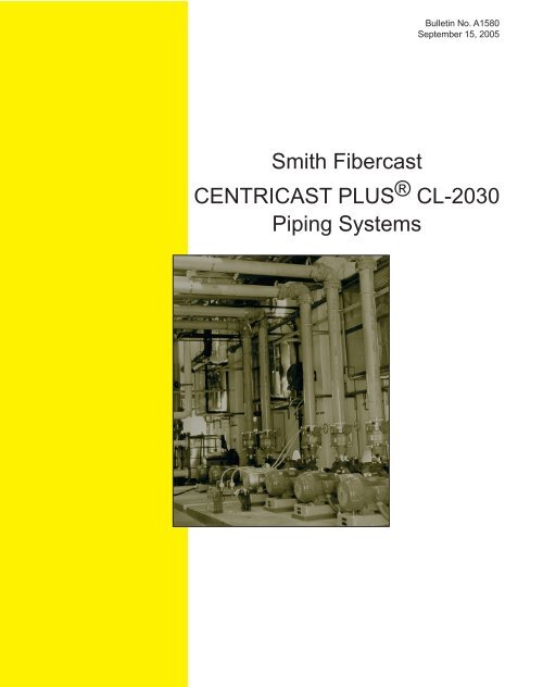
Smith Fibercast CENTRICAST PLUS®CL-2030 Piping Systems
Smith Fibercast CENTRICAST PLUS®CL-2030 Piping Systems
Smith Fibercast CENTRICAST PLUS®CL-2030 Piping Systems

You also want an ePaper? Increase the reach of your titles
YUMPU automatically turns print PDFs into web optimized ePapers that Google loves.
<strong>Smith</strong> <strong>Fibercast</strong><br />
Bulletin No. A1580<br />
September 15, 2005<br />
<strong>CENTRICAST</strong> PLUS ® CL-<strong>2030</strong><br />
<strong>Piping</strong> <strong>Systems</strong>
<strong>CENTRICAST</strong> PLUS ® CL-<strong>2030</strong> Pipe<br />
PRODUCT<br />
<strong>CENTRICAST</strong> PLUS CL-<strong>2030</strong> pipe is<br />
manufactured with high strength glass<br />
fabrics and a highly resilient formulation<br />
of corrosion resistant vinyl ester resin. A<br />
100 mil integral corrosion barrier of pure<br />
resin provides excellent corrosion resistance.<br />
It is recommended for most highly<br />
chlorinated or acidic mixtures up to<br />
175ºF and many other chemical up to<br />
200ºF. Centricast Plus CL-<strong>2030</strong> proprietary<br />
resin formulation also provides<br />
toughness for many corrosive types of slurries.<br />
Pipe and fittings are available in 1”-<br />
14” with static pressure ratings up to 150<br />
psig, with higher pressure ratings in smaller<br />
sizes. <strong>CENTRICAST</strong> PLUS CL-<strong>2030</strong><br />
comes in 20’ nominal or exact lengths.<br />
EXTERNAL BARRIER<br />
A 10 mil resin-rich reinforced external<br />
corrosion barrier provides excellent<br />
corrosion resistance and protection<br />
from ultraviolet (UV) radiation. CL-<br />
<strong>2030</strong> also contains a UV inhibitor for protection<br />
against “fiber blooming” caused<br />
by UV radiation. <strong>Smith</strong> <strong>Fibercast</strong> warrants<br />
<strong>CENTRICAST</strong> PLUS CL-<strong>2030</strong><br />
pipe and fittings against UV degradation<br />
of physical properties and chemical<br />
resistance for 15 years.<br />
FITTINGS<br />
Compatible vinyl ester fittings are manufactured<br />
with the same chemical resistance,<br />
temperature rating and performance capabilities<br />
as the pipe. The fabrication process<br />
is dependent on the fitting type and size.<br />
Fittings are manufactured by compression<br />
molding, contact molding or filament<br />
winding.<br />
JOINING METHODS<br />
An adhesive bonded socket connection<br />
with positive stops in the fittings is standard<br />
design. The use of positive stops<br />
simplifies close tolerance piping<br />
installation. This joining<br />
system is easy to install and<br />
no special tools are required<br />
for field assembly. The joint<br />
is prepared for bonding by<br />
lightly sanding the pipe O.D.<br />
and the mating fitting’s socket.<br />
A high strength adhesive<br />
with the same chemical<br />
resistance and temperature<br />
capabilities is used to bind the<br />
pipe and fittings. See Manual<br />
No. F6080 “Pipe Installation<br />
Handbook” for detailed installation<br />
instructions and fabrication<br />
techniques.<br />
RECOMMENDED SER-<br />
VICES<br />
<strong>CENTRICAST</strong> PLUS CL-<br />
<strong>2030</strong> vinyl ester resin pipe is<br />
excellent for many chemical<br />
and slurry applications including<br />
strong acids, chlorine<br />
2<br />
and oxidizing agents that corrode traditional<br />
metal pipe. Refer to Manual No. E5615<br />
“Chemical Resistance Guide” for proper<br />
application.<br />
BENEFITS<br />
The excellent chemical resistance of<br />
CL-<strong>2030</strong> piping system provides longer<br />
service life than traditional piping materials.<br />
CL-<strong>2030</strong>’s performance conveying<br />
chemical mixtures and strong acids<br />
is particularly exceptional resulting in a<br />
reduction in maintenance and replacement<br />
costs.<br />
CL-<strong>2030</strong> piping systems are light<br />
weight and easily installed. Reductions<br />
in labor costs and heavy handling equipment<br />
due to the ease of installation<br />
result in lower total installed costs.<br />
CL-<strong>2030</strong> pipe typically weighs less<br />
than ¼ that of comparable Schedule 40<br />
Stainless Steel. A 20’ length of 4” CL-<br />
<strong>2030</strong> weighs 58 lbs. while the same<br />
length of stainless steel weighs 216<br />
lbs.<br />
DISTRIBUTION<br />
FGS <strong>Smith</strong> <strong>Fibercast</strong> has a network<br />
of stocking distributors throughout the<br />
United States as well as representatives<br />
and distributors throughout the world.<br />
These distributors are supported by a<br />
staff of experienced application engineers<br />
and highly trained field service technicians<br />
strategically located around the<br />
world.
General Specifications and Dimensional Data*<br />
<strong>CENTRICAST</strong> PLUS ® CL-<strong>2030</strong> Pipe<br />
PIPE PROPERTIES<br />
Nominal Nominal<br />
Pipe Nominal Nominal Wall Reinforcement Nominal<br />
Size I.D. O.D. Thickness Thickness Weight Capacity<br />
(In.) (In.) (mm) (In.) (mm) (In.) (mm) (In.) (mm) (Lbs./Ft.) (kg/m) (Gal./Ft.) (Cu. Ft./Ft.)<br />
1 0.94 23.7 1.32 33.4 0.19 4.8 0.095 2.4 0.45 0.68 0.04 0.005<br />
1 1 /2 1.42 36.1 1.90 48.3 0.24 6.1 0.140 3.6 0.84 1.26 0.08 0.011<br />
2 1.86 47.1 2.38 60.3 0.26 6.6 0.150 3.8 1.16 1.74 0.14 0.019<br />
3 2.92 74.2 3.50 88.9 0.29 7.4 0.180 4.6 1.97 2.94 0.35 0.047<br />
4 3.84 97.5 4.50 114.3 0.33 8.4 0.220 5.6 2.91 4.35 0.60 0.080<br />
6 5.97 152.0 6.63 168.4 0.33 8.4 0.220 5.6 4.39 6.57 1.45 0.194<br />
8 7.97 202.0 8.63 219.2 0.33 8.4 0.220 5.6 5.78 8.65 2.59 0.348<br />
10 10.10 256.0 10.75 273.1 0.33 8.4 0.220 5.6 7.26 10.90 4.15 0.555<br />
12 12.10 307.0 12.75 323.9 0.33 8.4 0.220 5.6 8.65 13.00 5.96 0.797<br />
14 13.30 339.0 14.00 355.6 0.33 8.4 0.220 5.6 9.52 14.30 7.26 0.971<br />
* All values are nominal. Tolerances or maximum/minimum limits can be obtained from <strong>Smith</strong> <strong>Fibercast</strong>.<br />
ASTM D2997 Designation Codes †:<br />
1 - 11 /2” RTRP-22BS-3446<br />
2” - 6” RTRP-22BS-4446<br />
8” RTRP-22BS-4445<br />
10” - 12” RTRP-22BS-4444<br />
14” RTRP-22BS-4443<br />
† Mechanical properties cell<br />
classifications shown are minimum.<br />
Actual classifications<br />
may be higher for some sizes.<br />
Pressure Ratings for Uninsulated <strong>Piping</strong> <strong>Systems</strong> (1)(2)<br />
(1) Static pressure ratings, typically created with use of a gear pump, turbine<br />
pump, centrifugal pump, or multiplex pump having 4 or more pistons, or<br />
elevation head.<br />
(2) Specially fabricated higher pressure fittings are available on request. For<br />
insulated and/or heat traced piping systems, reduce pressure rating by<br />
30% for 175° to 200°F operating temperatures. For compressible gasses,<br />
consult the factory for pressure ratings. <strong>CENTRICAST</strong> CL-<strong>2030</strong> pipe and<br />
vinyl ester fittings can be used in insulated drainage and vent systems up<br />
to 200°F operating temperatures. Heat cured adhesive joints are highly<br />
recommended for all piping systems carrying fluids at temperatures above<br />
120°F.<br />
3<br />
Pipe Lengths Available<br />
Size<br />
(In.) Length (Ft.)<br />
1 - 14 20*<br />
Nominal Max. Internal Pressure @ 175°F (psig) Maximum External Pressure (6)<br />
Pipe Socket Flanged Other<br />
Size Pressure Pressure Pressure<br />
(In.) Fittings (3) Fittings (4) Fittings (5) @ 75°F @150°F @ 175°F<br />
1 300 300 NA 1975 1679 1383<br />
1 1 /2 300 300 NA 1034 878 775<br />
2 275 200 125 1013 861 759<br />
3 200 150 125 467 397 350<br />
4 150 150 100 425 361 319<br />
6 150 150 100 218 185 163<br />
8 150 150 100 69 59 52<br />
10 150 150 75 34 29 26<br />
12 150 150 75 43 36 32<br />
14 125 150 75 16 14 12<br />
* Pipe is offered in random or<br />
exact lengths. Random lengths<br />
are from 18.0 to 20.4 feet long.<br />
(3) Socket elbows, tees, reducers, couplings, flanges and nipples joined with<br />
WELDFAST CL-200 adhesive.<br />
(4) Flanged elbows, tees, reducers, couplings and nipples assembled at factory.<br />
(5) Laterals, crosses, saddles and grooved nipples.<br />
(6) Ratings shown are 50% of ultimate. 14.7 psi external pressure is equal to<br />
full vacuum.<br />
NA = Not available at time of printing.
<strong>CENTRICAST</strong> PLUS ® CL-<strong>2030</strong> Pipe<br />
Average Physical Properties (1)<br />
Size Size Size<br />
Property @ 75° F/ @ 24° C @ 150° F/ @ 66° C @ 175° F/ @ 80° C<br />
1” - 1 1 /2” 2” - 14” 1” - 1 1 /2” 2” - 14” 1” - 1 1 /2” 2” - 14”<br />
psi MPa psi MPa psi MPa psi MPa psi MPa psi MPa<br />
Axial Tensile – ASTM D2105<br />
Ultimate Stress 22,000 150 22,000 150 19,000 130 19,000 130 18,000 120 18,000 120<br />
Design Stress 5,500 38 5,500 38 4,750 33 4,750 33 4,500 31 4,500 31<br />
Modulus of Elasticity 2.1E+06 14500 2.1E+06 14500 1.8E+06 12400 1.8E+06 12400 1.8E+06 12400 1.8E+06 12400<br />
Poisson’s Ratio<br />
0.15 0.15 0.15<br />
Axial Compression – ASTM D695<br />
Ultimate Stress 26,000 180 32,000 220 24,000 170 30,000 210 18,000 120 22,000 150<br />
Design Stress 6,500 45 8,000 55 6,000 41 7,500 52 4,500 31 5,500 38<br />
Modulus of Elasticity 3.3E+06 22800 2.6E+06 17900 2.9E+06 20000 2.3E+06 15900 2.8E+06 19300 2.2E+06 15100<br />
Beam Bending – ASTM D2925<br />
Ultimate Stress 22,000 150 40,000 280 19,000 130 35,000 240 18,000 120 33,000 230<br />
Design Stress 2,750 19 5,000 34 2,375 16 4,375 30 2,250 16 4,125 28<br />
Modulus of Elasticity (long term) 3.3E+06 22800 3.3E+06 22800 2.9E+06 20000 2.9E+06 20000 2.8E+06 19300 2.8E+06 19300<br />
Hydrostatic Burst – ASTM D1599<br />
Ultimate Hoop Tensile Stress 25,000 170 30,000 210 21,000 140 26,000 180 20,000 140 25,000 170<br />
Hoop Tensile Modulus of Elasticity 3.0E+06 20700 3.2E+06 22100 2.6E+06 17900 2.8E+06 19300 2.5E+06 17200 2.7E+06 18600<br />
Hydrostatic Design – ASTM D2992,<br />
Procedure B – Hoop Tensile Stress (1)<br />
Static 50 Year @ 175°F – – – – – – – – 8,600 60 8,600 60<br />
Coefficient of Linear Thermal Expansion 8.9 x 10 -6 in./in./°F (Non-Insulated Pipe) • 16.1x10 -6 mm/mm°C (Non-Insulated Pipe)<br />
– ASTM D696 10.0 x 10 -6 in./in./°F (Insulated Pipe) • 18.1x10 -6 mm/mm°C (Insulated Pipe)<br />
Thermal Conductivity 0.07 BTU/(ft)(hr)(°F) • 0.04 W/(m)(°C)<br />
Specific Gravity (Density) 1.56 (0.056 Lb/in. 3) • (1.56 g/cm 3)<br />
Hazen-Williams Flow Factor C-150<br />
Surface Roughness 1.7 x 10 -5 Feet<br />
Manning’s “n” 0.009<br />
(1) Stress and modulus values can be interpolated between temperatures shown. Consult the factory for Modulus of Elasticity values between 175°F and 225°F.<br />
Properties of Pipe Sections Based on<br />
Minimum Reinforced Walls<br />
Size Reinforcement Reinforcement Reinforcement Total Wall<br />
(In.) End Area (In. 2 ) Moment of Inertia (In. 4 ) Section Modulus (In. 3 ) End Area (In. 2 )<br />
1 0.36 0.07 0.10 0.67<br />
1 1 /2 0.77 0.30 0.32 1.25<br />
2 1.05 0.65 0.55 1.73<br />
3 1.88 2.59 1.48 2.92<br />
4 2.96 6.79 3.02 4.32<br />
6 4.43 22.70 6.86 6.53<br />
8 5.81 51.30 11.90 8.60<br />
10 7.28 100.00 18.80 10.80<br />
12 8.66 170.00 26.70 12.90<br />
14 9.52 226.00 32.30 14.20<br />
4
Recommended Operating Ratings<br />
<strong>CENTRICAST</strong> PLUS ® CL-<strong>2030</strong> Pipe<br />
Axial Bending Torque Parallel Plate Loading (3)<br />
Axial<br />
Compressive Loads<br />
Tensile Loads Radius Max. @ 5% Deflection & 75°F<br />
Max. (Lbs.) Max. (Lbs.) Min. (Ft.) (Ft.•Lbs.) ASTM D2412<br />
Size Entire Entire Stiffness Pipe Hoop<br />
(In.) @ @ @ @ Temp. Temp. Factor Stiffness Modulus<br />
75° F 175°F (1) 75° F 175°F (1)(2) Range Range In. 3 •Lbs./In. 2 (psi) x 10 6 (psi)<br />
1 2000 1600 2400 1600 66 43 143 4225 2.0<br />
11 /2 4300 3500 5000 3500 95 132 457 4504 2.0<br />
2 5800 4700 8400 5800 65 229 563 2742 2.0<br />
3 10300 8400 15000 10300 96 618 1215 1783 2.5<br />
4 16300 13300 23700 16300 124 1260 2218 1519 2.5<br />
6 24300 19900 35400 24300 182 2860 2218 453 2.5<br />
8 32000 26100 46500 32000 237 4960 2662 241 3.0<br />
10 40000 32800 58200 40000 296 7820 2662 122 3.0<br />
12 47600 39000 69300 47600 351 11100 2662 73 3.0<br />
14 52400 42900 76200 52400 385 13500 2662 55 3.0<br />
(1) Consult the factory for design recommendations above 175°F.<br />
(2) Compressive loads are for short columns only. Buckling loads<br />
must be calculated when applicable.<br />
The following engineering analysis must be performed to<br />
determine the maximum support spacing for the piping system.<br />
Proper pipe support spacing depends on the temperature and<br />
weight of the fluid carried in the pipe. The support spacing is<br />
calculated using continuous beam equations and the pipe bending<br />
modulus derived from long-term beam bending tests. The<br />
following tables were developed to ensure a design that limits<br />
beam mid-span deflection to 1 /2 inch and bending stresses to<br />
less than or equal to 1 /8 of the ultimate bending stress. Any additional<br />
weight on the piping system such as insulation or heat<br />
tracing requires further consideration. Restrained (anchored)<br />
piping systems operating at elevated temperatures often result<br />
in guide spacing requirements that are more stringent than simple<br />
unrestrained piping systems. In this case, the maximum<br />
guide spacing will dictate the support/guide spacing requirements<br />
for the system. Pipe support spans at changes in direction<br />
require special attention. Supported and unsupported fittings<br />
at changes in direction are considered in the following<br />
tables and must be followed to properly design the piping system.<br />
There are seven basic rules to follow when designing piping<br />
system supports, anchors, and guides:<br />
1 Do not exceed the recommended support span.<br />
2 Support valves and heavy in-line equipment independently .<br />
This applies to both vertical and horizontal piping.<br />
3 Protect pipe from external abrasion.<br />
4 Avoid point contact loads.<br />
(3) Burial calculations should be based on 5% deflection as shown in<br />
table above.<br />
SUPPORTS<br />
5<br />
5 Avoid excessive bending. This applies to handling, transporting,<br />
initial layout, and final installed position.<br />
6. Avoid excessive vertical run loading. Vertical loads should<br />
be supported sufficiently to minimize bending stresses at<br />
outlets or changes in direction.<br />
7. Provide adequate axial and lateral restraint to ensure line<br />
stability during rapid changes in flow.<br />
Maximum Support Spacing<br />
for Uninsulated Pipe*<br />
Continuous Spans of Pipe (Ft.)<br />
Specific Gravity=1.0, Deflection= 1 /2”<br />
Nom. Temperature<br />
Pipe Size<br />
(In.) 75°F 150°F 175°F<br />
1 13.5 13.1 13.0<br />
1 1 /2 16.4 15.9 15.8<br />
2 17.9 17.3 17.2<br />
3 21.0 20.4 20.2<br />
4 23.7 22.9 22.7<br />
6 26.7 25.8 25.6<br />
8 28.8 27.9 27.7<br />
10 30.7 29.7 29.4<br />
12 32.2 31.1 30.9<br />
14 33.0 31.9 31.7<br />
* Consult factory for insulated pipe support spacing and operating<br />
temperatures between 175°F and 200°F.
<strong>CENTRICAST</strong> PLUS ® CL-<strong>2030</strong> Pipe<br />
Support Spacing vs. Specific Gravity<br />
Specific<br />
Gravity 3.00 2.00 1.50 1.25 1.00 0.75 Gas/Air<br />
Multiplier 0.76 0.84 0.90 0.95 1.00 1.07 1.40<br />
Example: 6” pipe @ 150°F with 1.5 specific gravity fluid, maximum support spacing = 23.8 x 0.9 = 21.4 ft.<br />
<strong>Piping</strong> Span Adjustment Factors With<br />
Unsupported Fitting at<br />
Change in Direction<br />
Span Type Factor<br />
a Continuous interior or fixed end spans 1.00<br />
b Second span from simple supported 0.80<br />
end or unsupported fitting<br />
c + d Sum of unsupported spans at fitting < 0.75*<br />
e Simple supported end span 0.67<br />
a a a b c<br />
d b a b<br />
*For example: If continuous support span is 10 ft., c + d must not<br />
exceed 7.5 ft. (c = 3 ft. and d = 4.5 ft. would satisfy this condition).<br />
The effects of thermal gradients on piping systems may be significant<br />
and should be considered in every piping system stress<br />
analysis. Pipe line movements due to thermal expansion or contraction<br />
may cause high stresses or even buckle a pipe line if<br />
improperly restrained. Several piping system designs are used to<br />
manage thermal expansion and contraction in above ground piping<br />
systems. They are listed below according to economic preference:<br />
1. Use of inherent flexibilities in directional changes<br />
2. Restraining axial movements and guiding to prevent<br />
buckling<br />
3. Use expansion loops to absorb thermal movements<br />
4. Use mechanical expansion joints to absorb thermal<br />
movements<br />
e<br />
<strong>Piping</strong> Span Adjustment Factors With<br />
Supported Fitting at Change in<br />
Direction<br />
Type of Span Adjustment Factor<br />
a Continuous interior or fixed end spans 1.00<br />
b Span at supported fitting or span adjacent 0.80<br />
to a simple supported end<br />
e Simple supported end span 0.67<br />
a a a a b<br />
THERMAL EXPANSION<br />
6<br />
b a a b<br />
To perform a thermal analysis the following information is<br />
required:<br />
1. Isometric layout of piping system<br />
2. Physical and material properties of pipe<br />
3. Design temperatures<br />
4. Installation temperature (Final tie in temperature)<br />
5. Terminal equipment load limits<br />
6. Support movements<br />
A comprehensive review of temperature effects on fiberglass<br />
pipe may be found in <strong>Smith</strong> <strong>Fibercast</strong>’s “Engineering and<br />
<strong>Piping</strong> Design Guide”, Manual No. E5000, Section 3.<br />
e
Unrestrained<br />
Thermal Expansion<br />
Uninsulated Pipe (1)<br />
Change in Pipe Change<br />
Temperature in Length<br />
(°F) (In./100 Ft.)<br />
25 0.27<br />
50 0.53<br />
75 0.80<br />
100 1.07<br />
125 1.34<br />
150 1.60<br />
175 1.87<br />
200 2.14<br />
(1) Consult the factory for thermal expansion and compressive<br />
end loads of insulated pipe.<br />
<strong>CENTRICAST</strong> PLUS ® CL-<strong>2030</strong> Pipe<br />
Restrained Thermal Expansion<br />
Pipe Compressive End Loads<br />
Uninsulated Pipe (1)<br />
Nominal End Nominal End<br />
Pipe Size Loads Pipe Size Loads<br />
(in) (Lbs./°F) (in) (Lbs./°F)<br />
1 10.69 6 102.44<br />
11 /2 22.73 8 134.42<br />
2 30.79 10 168.41<br />
3 43.44 12 200.40<br />
4 68.45 14 220.39<br />
Maximum Guide Spacing for Restrained Thermal End Loads (Feet)<br />
Nominal<br />
Pipe Size Temperature Change °F*<br />
(In.) 25 50 75 100 125 150 175 200<br />
1 7.0 4.9 4.0 3.5 3.1 2.9 2.6 2.5<br />
11 /2 10.1 7.1 5.8 5.0 4.5 4.1 3.8 3.6<br />
2 14.4 10.2 8.3 7.2 6.4 5.9 5.4 5.1<br />
3 21.4 15.1 12.4 10.7 9.6 8.7 8.1 7.6<br />
4 27.6 19.5 15.9 13.8 12.3 11.3 10.4 9.8<br />
6 41.3 29.2 23.8 20.6 18.5 16.8 15.6 14.6<br />
8 54.1 38.3 31.3 27.1 24.2 22.1 20.5 19.1<br />
10 67.8 48.0 39.2 33.9 30.3 27.7 25.6 24.0<br />
12 80.7 57.1 46.6 40.3 36.1 32.9 30.5 28.5<br />
14 88.7 62.8 51.2 44.4 39.7 36.2 33.5 31.4<br />
*Note: Temperature Change = Maximum Fluid Temperature - Installation Temperature.<br />
Expansion Loop Minimum Leg Length (Feet)*<br />
Total Deflection to be Absorbed (inches)<br />
Size (In.) 1/2 1 2 3 4 5 6 7 8 9 10<br />
1 2.9 4.1 5.8 7.2 8.3 9.2 10.1 10.9 11.7 12.4 13.1<br />
11 /2 3.5 5.0 7.0 8.6 9.9 11.1 12.2 13.1 14.0 14.9 15.7<br />
2 2.9 4.1 5.8 7.1 8.2 9.2 10.0 10.8 11.6 12.3 13.0<br />
3 4.0 5.6 7.9 9.7 11.2 12.5 13.7 14.8 15.8 16.8 17.7<br />
4 5.5 7.7 10.9 13.4 15.5 17.3 19.0 20.5 21.9 23.2 24.5<br />
6 6.3 8.9 12.6 15.4 17.8 19.9 21.8 23.5 25.1 26.7 28.1<br />
8 7.2 10.2 14.4 17.6 20.3 22.7 24.9 26.9 28.7 30.5 32.1<br />
10 8.0 11.3 16.0 19.6 22.7 25.3 27.8 30.0 32.1 34.0 35.8<br />
12 8.7 12.2 17.3 21.2 24.5 27.4 30.0 32.4 34.6 36.7 38.7<br />
14 8.0 11.4 16.1 19.7 22.8 25.5 27.9 30.1 32.2 34.1 36.0<br />
*Note: Multiply expansion loop minimum leg length by 1.414 for directional change contilever leg length.<br />
7<br />
Allowable<br />
Bending Moment<br />
90° Elbow<br />
Nominal Allowable Nominal Allowable<br />
Pipe Size Moment Pipe Size Moment<br />
(in) (Ft•Lbs.) (in) (Ft•Lbs.)<br />
1 100 6 1,650<br />
11 /2 150 8 2,850<br />
2 225 10 4,500<br />
3 475 12 6,500<br />
4 650 14 10,000
<strong>CENTRICAST</strong> PLUS ® CL-<strong>2030</strong> Pipe<br />
See Section 3 of <strong>Smith</strong> <strong>Fibercast</strong> Manual No. F6080, Pipe<br />
Installation Handbook: Hydrostatic Testing and System Start<br />
Up.<br />
When possible, <strong>Smith</strong> <strong>Fibercast</strong> piping systems should be<br />
hydrostatically tested prior to being put into service. Care<br />
should be taken when testing, as in actual installation, to avoid<br />
Water (Fluid) Hammer<br />
A high pressure surge may be created that interrupts flow in<br />
the event of a pump startup or a quick closing valve. This surge<br />
can be significantly reduced by controlling pump startup and<br />
valve closure rates.<br />
The maximum pressure surge in psig caused by water hammer<br />
can be calculated by multiplying the fluid velocity in ft./sec. times the<br />
constant listed in this table. The instantaneous peak pressure for<br />
the system will equal the water hammer surge plus the pressure in<br />
the system at the time the water hammer occurred.<br />
® Trademarks of Varco I/P, Inc.<br />
© 2005, National Oilwell Varco<br />
TESTING<br />
water hammer. All anchors, guides and supports must be in<br />
place prior to testing the line.<br />
Test pressure should not be more than 1 1 ¼2 times the working<br />
pressure of the piping system and never exceed 1 1 ¼2 times<br />
the rated operating pressure of the lowest rated component in<br />
the system.<br />
OTHER CONSIDERATIONS<br />
P.O. Box 968 • 25 South Main • Sand Springs, OK 74063<br />
(918) 245-6651 • Fax: (918) 245-7566 or Fax: (800) 365-7473<br />
2700 West 65th Street • Little Rock, AR 72209<br />
(501) 568-4010 • Fax: (501) 568-4465<br />
http://www.smithfibercast.com<br />
Water (Fluid) Hammer Constants (1)<br />
Nominal Nominal<br />
Pipe Size Pipe Size<br />
(in) Constants (in) Constants<br />
1 45.1 6 33.8<br />
11 /2 44.8 8 30.3<br />
2 43.2 10 27.6<br />
3 40.0 12 25.6<br />
4 39.1 14 24.6<br />
(1) Constants<br />
are valid for<br />
water at 75°F.<br />
It is the policy of Fiber Glass <strong>Systems</strong> to improve its products continually. In accordance with that policy, the right is<br />
reserved to make changes in specifications, descriptions, and illustrative material contained in this bulletin as conditions<br />
warrant. Always cross-reference the bulletin date with the most current version listed at<br />
www.smithfibercast.com. The information contained herein is general in nature and is not intended to express any<br />
warranty of any type whatsoever, nor shall any be implied.<br />
PRINTED IN USA, 5M0905