Series II AVT-44⢠Data Sheet - Sound Control Technologies Inc
Series II AVT-44⢠Data Sheet - Sound Control Technologies Inc
Series II AVT-44⢠Data Sheet - Sound Control Technologies Inc

You also want an ePaper? Increase the reach of your titles
YUMPU automatically turns print PDFs into web optimized ePapers that Google loves.
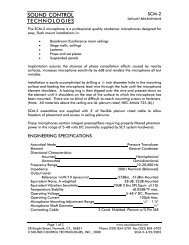
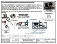
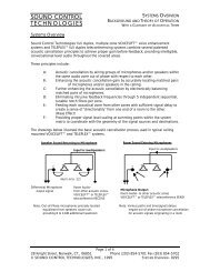
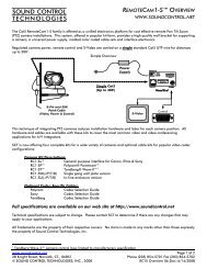
SOUND CONTROLTECHNOLOGIES<strong>Series</strong> <strong>II</strong> <strong>AVT</strong>-44 INSTALLATION MANUALAUDIO/VIDEO TELECONFERENCING INTERFACEBIOS 3.06/ HOST 3.16/ DSP 0.35PLEASE READ CAREFULLY PRIOR TO INSTALLING <strong>AVT</strong>-44Index Of Topics:I. Wiring The <strong>AVT</strong>-44Audio Levels<strong>II</strong>. On-site Set-upA. 4 Wire Set-upB. 2 Wire Set-up<strong>II</strong>I. <strong>Control</strong>ling The <strong>AVT</strong>-44I. Wiring The <strong>AVT</strong>-44The <strong>AVT</strong>-44 provides for both microphone inputs and line level inputs into the system. Up to fourcondenser type microphones can be connected directly to the <strong>AVT</strong>-44’s rear XLR type connectors.PUSH PUSH PUSH PUSHMIC A MIC B MIC C MIC DRear view of the <strong>AVT</strong>-44 XLR connectors.All line level audio connections to the <strong>AVT</strong>-44 are made to the rear of the unit via “RCA” typeconnectors and are clearly marked.RECORD4W SNDLINE OUTOUTAUX4W RCVLINE ININRear view of the <strong>AVT</strong>-44 “RCA” connectors.Using the <strong>AVT</strong>-44 in the 2-wire mode requires a standard analog telephone line or voice qualityanalog extension from an "in-house" telephone system. The main telephone line connects to the RJ-11 modular connector labeled "Line". For dialing and ringing of incoming calls, a telephone may beconnected to the RJ-11 modular connector labeled "Phone", or these functions may be accommodatedvia the RS-232 ports.www.soundcontrol.net Page 1 of 1228 Knight Street, Norwalk, CT., 06851 Phone (203) 854-5701 Fax (203) 854-5702© SOUND CONTROL TECHNOLOGIES, INC., 2004 44_MAN2A.DOC -2/27/2004
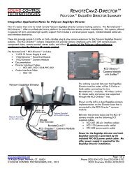
SOUND CONTROLTECHNOLOGIES<strong>Series</strong> <strong>II</strong> <strong>AVT</strong>-44 INSTALLATION MANUALAUDIO/VIDEO TELECONFERENCING INTERFACEBIOS 3.06/ HOST 3.16/ DSP 0.35PHONELINEANALOG TELEPHONE INTERFACERear view of the <strong>AVT</strong>-44 RJ-11 telephone connections.When used in conjunction with SCT Systems, all set up,( including room notching procedures forVOICELIFT Systems) wiring check-out and microphone balancing procedures must be thoroughlycompleted prior to <strong>AVT</strong>-44 start up.MADEINUSASOUND CONTROLTECHNOLOGIES28 Knight Street, Norwalk, CT 06851REAR VIEW <strong>AVT</strong>-44 (Fig. 1)COM 1COM 2PHONELINERECORD4W SNDLINE OUTOUTPUSH PUSH PUSH PUSH100-135VAC200-270VAC50-100 Hz1.2A MAXLOUDSPEAKERANALOG TELEPHONE INTERFACEAUX4W RCVINLINE INMIC A MIC B MIC C MIC DAudio LevelsAll line level audio inputs to the <strong>AVT</strong>-44, (“LINE IN”, “4-WIRE RCV. IN” and “AUX IN”) are designed for anominal -6.8 dBm (1V peak to peak) signal.FOR AUDIOLINK and AUDIOLINK PLUS SYSTEMS:REAR VIEW AUDIOLINK (Fig 2)REAR VIEW AUDIOLINK PLUS (Fig 3)95-135VAC50/60Hz1A MAX.SOUND CONTROL TECHNOLOGIESLOUDSPEAKERSD C+ - + -B A+ - + -MICROPHONEACTIVITYINCPVCY+ -28 Knight StreetNorwalk, CT 06851XPND IN SNDOUT+ - s +Interfacing the AUDIOLINK and/or AUDIOLINK PLUS for additional microphone and loudspeakersupport is done through "Room Rcv. Out " and "Room Send In" on the <strong>AVT</strong>-44."LINE Out" on the <strong>AVT</strong>-44 connects to "RCV IN" on the AUDIOLINK or AUDIOLINK PLUS forthe distant party's signal to reach the loudspeakers.The microphone signal from the AUDIOLINK or AUDIOLINK PLUS is "SND OUT". This connectsto "LINE In" on the <strong>AVT</strong>-44www.soundcontrol.net Page 2 of 1228 Knight Street, Norwalk, CT., 06851 Phone (203) 854-5701 Fax (203) 854-5702© SOUND CONTROL TECHNOLOGIES, INC., 2004 44_MAN2A.DOC -2/27/2004
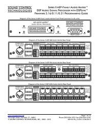
SOUND CONTROLTECHNOLOGIES<strong>Series</strong> <strong>II</strong> <strong>AVT</strong>-44 INSTALLATION MANUALAUDIO/VIDEO TELECONFERENCING INTERFACEBIOS 3.06/ HOST 3.16/ DSP 0.35Pin-out instructions for customized MATRIX Systems are included in the SCT System DocumentationManual for that system.<strong>II</strong>.On-site Set-up:FUNCTIONDOWNUPMICMODEINTEGRATEDTELECONFERENCE INTERFACEOFFONSuccessive pushes of the MODE button will scroll through the following options on the LCD display:Step Line 1 Line 2 Options1 Mode: 2-WIRE = OFF ON / OFF2 Mode: 2-WIRE PVC = OFF ON / OFF3 Mode: 4-WIRE = OFF ON / OFF4 Mode: 4-WIRE PVC = OFF ON / OFF5 Mode: PUSH ON TO TRAIN TRAIN SYSTEM (3 SEC)6 Mode: PUSH ON TO SAVE SAVE SYSTEM SETTINGS7 Mode: 4W->2W PVC = OFF ON / OFF8 Mode: 2W->4W PVC = OFF ON / OFF9 Mode: OFF FOR DEFAULTS FACTORY DEFAULTS10 Mode: MIC SETUP = OFF Mic Level Mode11 Mode: PWR ON = 4W OFF POWER ON 4W ON/OFF12 Mode: RS FILTR = 120Hz 120/250/500/75013 Mode: 4WSND MUTE = OFF ON / OFF14 Mode: LEC BYPASS = OFF TEMPORARY LEC BYPASS15 Mode: AEC BYPASS = OFF TEMPORARY AEC BYPASS16 Mode: AEC SIZE = LONG SHORT / LONG17 Mode: AUTO-DISC = OFF ON / OFF18 Mode: TEST = OFF Enables Pink NoiseSuccessive pushes of the FUNCTION button will scroll through the following:Step Line 1 Line 2 Options1 FUNCTION: 2W RCV : 0.0 dB ±6 dB in 1.5 dB Steps2 FUNCTION: 2W SND : 0.0 dB +12/-6 dB in 1.5 dB Steps3 FUNCTION: 2W A/D : 0.0 dB ±6 dB in 1.5 dB Steps4 FUNCTION: 4W RCV : 0.0 dB ±6 dB in 1.5 dB Steps5 FUNCTION: 4W SND : 0.0 dB ±6 dB in 1.5 dB Steps6 FUNCTION: 4W A/D : 0.0 dB ±6 dB in 1.5 dB Steps7 FUNCTION: RM SND : 0.0 dB ±6 dB in 1.5 dB Steps8 FUNCTION: AUX-IN : 0.0 dB ±6 dB in 1.5 dB Steps9 FUNCTION: AUX>SND: 0.0 dB ±6 dB in 1.5 dB Steps10 FUNCTION: AUX>RM : 0.0 dB ±6 dB in 1.5 dB Steps11 FUNCTION: AUX>REC: 0.0 dB ±6 dB in 1.5 dB Steps12 FUNCTION: 4>2 BRG: 0.0 dB ±6 dB in 1.5 dB Steps13 FUNCTION: 2>4 BRG: 0.0 dB ±6 dB in 1.5 dB Steps14 FUNCTION: 2W D/A : 0.0 dB ±6 dB in 1.5 dB Stepswww.soundcontrol.net Page 3 of 1228 Knight Street, Norwalk, CT., 06851 Phone (203) 854-5701 Fax (203) 854-5702© SOUND CONTROL TECHNOLOGIES, INC., 2004 44_MAN2A.DOC -2/27/2004
SOUND CONTROLTECHNOLOGIES<strong>Series</strong> <strong>II</strong> <strong>AVT</strong>-44 INSTALLATION MANUALAUDIO/VIDEO TELECONFERENCING INTERFACEBIOS 3.06/ HOST 3.16/ DSP 0.3515 FUNCTION: 4W D/A : 0.0 dB ±6 dB in 1.5 dB Steps16 FUNCTION: RM RCV : 0.0 dB ±6 dB in 1.5 dB Steps17 FUNCTION: RECORD : 0.0 dB ±6 dB in 1.5 dB StepsSuccessive pushes of the MIC button will scroll through the following:Step Line 1 Line 2 Options1 FUNCTION: MIC A : 16 MUTE, 1 – 32 1 dB Steps2 FUNCTION: MIC B : 16 MUTE, 1 – 32 1 dB Steps3 FUNCTION: MIC C : 16 MUTE, 1 – 32 1 dB Steps4 FUNCTION: MIC D : 16 MUTE, 1 – 32 1 dB Steps5 FUNCTION: LINE IN : 16 MUTE, 1 – 32 1 dB Steps6 FUNCTION: MIC MASTER : 26 MUTE, 1 – 32 3 dB Steps7 FUNCTION: SPEAKER : 16 MUTE, 1 – 32 1 dB StepsOn "power up" there will be a 3 second sign-on message:SOUND CONTROL<strong>AVT</strong>-44 BIOS 3.06followed by a 3 second "External <strong>Control</strong>s" message:SOUND CONTROL<strong>AVT</strong>-44 VER 3.16then the "standby" display appearsMODE: STANDBYSTATUS: OK v0.35The SCT <strong>AVT</strong>-44 seriesof DSP signal processorsare serial port firmwareupgradeable.The VER(sion) numberreflects the firmware levelof the unit.To upgrade systemfirmware contact yoursystem installer or SCT.SET UP SEQUENCEInitializing and TrainingNote: The <strong>AVT</strong>-44 echo cancellers are fully adaptive. "Initialization" and "Training" brings thesystem to optimization for the installed environment, accelerating the routine adaptive process. Oncethese coefficients have been initialized and saved, the system will then continuously adapt to changesin room occupancy, movement or similar transient situations.A. 4 WIRE INITIALIZATION:FUNCTIONDOWNUPMICMODEINTEGRATEDTELECONFERENCE INTERFACEOFFONSTEPACTION1. With the MODE button:Scroll toMODE: 4W ON/OFFwww.soundcontrol.net Page 4 of 1228 Knight Street, Norwalk, CT., 06851 Phone (203) 854-5701 Fax (203) 854-5702© SOUND CONTROL TECHNOLOGIES, INC., 2004 44_MAN2A.DOC -2/27/2004
SOUND CONTROLTECHNOLOGIES<strong>Series</strong> <strong>II</strong> <strong>AVT</strong>-44 INSTALLATION MANUALAUDIO/VIDEO TELECONFERENCING INTERFACEBIOS 3.06/ HOST 3.16/ DSP 0.35STATUS: 4W OFF2. Press "ON", the 4 wire LED will light3. With the MODE button:Scroll toMODE: TRAINON TO TRAIN( Room should be quiet with no movement)4. Training sound Pink Noise will be heard for 5 seconds.5. Echo canceller training is automatically saved to non-volatile memory. The <strong>AVT</strong>-44will now use this training as an adaptive starting point for all future conferences.6. Scroll to MODE: 4W ON/OFFSTATUS: 4W ON7. Press "OFF", the 4 wire LED will go offB. 2 WIRE INITIALIZATION:STEPACTIONPlace a standard telephone call. Using the system telephone handset place a call. Verify thatcall is connected and an acceptable quality line has been established, then:1. With the MODE button:Scroll toMODE: 2W ON/OFFSTATUS: 2W OFF2. Press "ON", the 2 wire LED will lightThe call is now on the "SYSTEM" The far party will probably hear apronounced echo.3. Scroll to MODE: TRAINON TO TRAIN( Room should be quiet with no movement)4. Training sound Pink Noise will be heard for 5 seconds.5. Echo canceller training is automatically saved to non-volatile memory. The <strong>AVT</strong>-44will now use this training as an adaptive starting point for all future conferences.6. Scroll to MODE: 2W ON/OFFSTATUS: 2W ON7. Press "OFF", the 2 wire LED will go offwww.soundcontrol.net Page 5 of 1228 Knight Street, Norwalk, CT., 06851 Phone (203) 854-5701 Fax (203) 854-5702© SOUND CONTROL TECHNOLOGIES, INC., 2004 44_MAN2A.DOC -2/27/2004
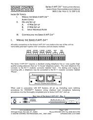
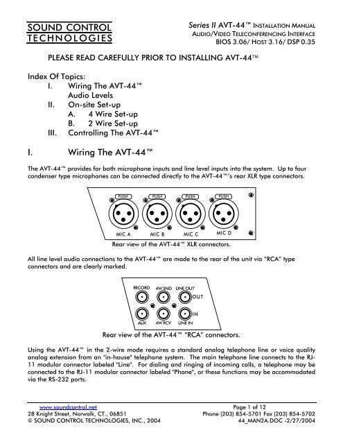
SOUND CONTROLTECHNOLOGIES<strong>Series</strong> <strong>II</strong> <strong>AVT</strong>-44 INSTALLATION MANUALAUDIO/VIDEO TELECONFERENCING INTERFACEBIOS 3.06/ HOST 3.16/ DSP 0.35This training process is generally only required at initial system set-up or if a significant change ismade to the room. Retraining, (Step 3 in either mode) may be done at any time.After a change in the general system level settings, a new "training" should be done.A "starting point" has now been established for the echo cancellers. Since a model of the room andline has been created in coefficient memory, this model is essentially the impulse response of theroom/line.Reviewing this data can show the effectiveness of acoustic treatment and provide an indication of therelative intelligibility of the teleconference room.Coefficient values can range from ±1.0, although proper set up should produce coefficients within ±0.5 at initial burst, decaying steadily over the next few hundred milliseconds. High initial coefficientsgenerally relates to inadequate room physical acoustic treatment.The following diagram is a plot of typical amplitude and time coefficient values of the room.Figure 3Plot of Room Echo Canceller coefficientswww.soundcontrol.net Page 6 of 1228 Knight Street, Norwalk, CT., 06851 Phone (203) 854-5701 Fax (203) 854-5702© SOUND CONTROL TECHNOLOGIES, INC., 2004 44_MAN2A.DOC -2/27/2004
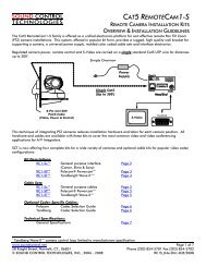
SOUND CONTROLTECHNOLOGIES<strong>Series</strong> <strong>II</strong> <strong>AVT</strong>-44 INSTALLATION MANUALAUDIO/VIDEO TELECONFERENCING INTERFACEBIOS 3.06/ HOST 3.16/ DSP 0.35<strong>II</strong>I.<strong>Control</strong>ling The <strong>AVT</strong>-44The <strong>AVT</strong>-44 has been designed to accept instructions from remote locations via RS-232 commandsthrough either of 2 rear serial ports (COM 1, COM 2).<strong>AVT</strong>-44 Rear ViewPin 17, N/CPin 12, RXD, Receive RS-232Pin 16, N/CPin 11, +V, For SCT peripheralsPin 3, TXD, Transmit RS-232Pin 8, N/CPin 4, N/CPin 9, N/CPin 5, GROUNDSOUND CONTROLTECHNOLOGIESCOM 1, 9 Pin "D", Male95-135VAC50/60Hz1.2 A MAX.28 Knight Street, Norwalk, CT 0651LOUDSPEAKERCOM 2, 9 Pin "D", FemalePin 15, GROUNDPin 19, N/CPin 14, N/CPin 18, N/CPin 11, +V, For SCT peripheralsPin 16, N/CPin 12, RXD, Receive RS-232Pin 17, N/CPin 13, TXD, Transmit RS-232Rear view of the <strong>AVT</strong>-44 serial port, loudspeaker and power connections.The RT-3P is wired from its 6 pin RJ-11 connectors to the <strong>AVT</strong>-44 COM-1 or COM 2 port.Null modem wiring between the <strong>AVT</strong>-44 and RT-3P remote control.<strong>AVT</strong>-44 Com PortPosition 1, +8VDCPosition 2, RXD (+)Position 3, TXD (+)Position 4, NCPosition 5, GroundPosition 6, NCPosition 7, NCPosition 8, NCPosition 9, NCRT-3PPosition 1, TXD (+)Position 2, GroundPosition 3, RXD (-)Position 4, TXD (-)Position 5, +8VDCPosition 6, RXD (+)Null modem wiring betweenthe <strong>AVT</strong>-44 and RT-3Pwww.soundcontrol.net Page 7 of 1228 Knight Street, Norwalk, CT., 06851 Phone (203) 854-5701 Fax (203) 854-5702© SOUND CONTROL TECHNOLOGIES, INC., 2004 44_MAN2A.DOC -2/27/2004
SOUND CONTROLTECHNOLOGIES<strong>Series</strong> <strong>II</strong> <strong>AVT</strong>-44 INSTALLATION MANUALAUDIO/VIDEO TELECONFERENCING INTERFACEBIOS 3.06/ HOST 3.16/ DSP 0.35SCT's RT-3P wired remote RS-232 control unit for the <strong>AVT</strong>-44 telephone interface is factoryprogrammed for the following functions with an LCD screen display:* ON/OFF transfer of the teleconference call* VOLUME CONTROL - RECEIVE sound UP/DOWN level into the room* PRIVACY* Last call REDIAL* KEY PAD DTMF dialingSOUND CONTROLTECHNOLOGIESRT-3P2 X 16 LDC DISPLAYVOLUMEUPVOLUMEDOWMPRIVACYFLASH1ABC2DEF3REDIALGHI4JKL5MNO6ONPRS7TUV8WXY9OFFOPER* #01. Systems using the SCT RT-3P interface through the COM-1 Serial Port can raise or lower theROOM volume (2WRCV) from the RT-3P keypad. Each step UP or DOWN is 1½ dB. (See the RT-3PInstruction <strong>Sheet</strong>)2. Systems being controlled by integrated remote control systems can control volume SEND orRECEIVE through COM 1 or COM 2.www.soundcontrol.net Page 8 of 1228 Knight Street, Norwalk, CT., 06851 Phone (203) 854-5701 Fax (203) 854-5702© SOUND CONTROL TECHNOLOGIES, INC., 2004 44_MAN2A.DOC -2/27/2004
SOUND CONTROLTECHNOLOGIES<strong>Series</strong> <strong>II</strong> <strong>AVT</strong>-44 INSTALLATION MANUALAUDIO/VIDEO TELECONFERENCING INTERFACEBIOS 3.06/ HOST 3.16/ DSP 0.35The following commands can be used to control various functions in the <strong>AVT</strong>-44 via computer, modem orother device capable of serial data transmission.Commands:1: STATUS= E Screen DisplayDevice Registration DEVICE=<strong>AVT</strong>-44Host Software Ver. VERSION=n.nnDSP Software Ver. DSPVERSION=0000xxTwo Wire Status 2WIRE=(1 or 0)Four Wire Status 4WIRE=(1 or 0)Privacy Status PRVCY=(0 - 5)Auto Answer Status AA=(0 or 1 - 9)2W Receive Level 2WRCV=X (0 - 9)2W A/D Level 2WA/D=X (0 - 9)2W Send Level 2WSND=X (0 - 9)Room Receive Level RMRCV=X (0 - 9)Room Send Level RMSND=X (0 - 9)4W Receive Level 4WRCV=X (0 - 9)4W A/D Level 4WA/D=X (0 - 9)4W Send Level 4WSND=X (0 - 9)Record Level RECORD=X (0 - 9)Aux In AUXIN=X (0 - 9)VU LevelsVU=x,x,x,x,x,x,xMIC_A Level MIC-A=Y (0 - 32)MIC_B Level MIC-B=Y (0 - 32)MIC_C Level MIC-C=Y (0 - 32)MIC_D Level MIC-D=Y (0 - 32)Line Level In LINE-IN=Y (0-32)MIC_MASTER MIC-MSTR=Z (0-32)MIX_MASTER MIX-MSTR=Z (0-32)Speaker Level SPEAKER=Z (0-32)Push Button Lock LOCK=0/1Mode Change Report REPORT=0/1External Relay Mode RLYMODE=0/1External Relay Port RLYPORT=0/1Serial Port 1 COM1=X (0 - 9)Serial Port 2 COM2=X (0 - 6)Aux In Record AUXREC=X (0 - 9)Aux In Room AUXRM=X (0 - 9)Aux In Send AUXSND=X (0 - 9)Power On Default PWRON4W=0/1Mute for Room Out M-MUTE=0/1End of STATUS Report @Notes:X- values are Y- values are“0-8” levels “M-32” levels8 = +6.0 dB M= Mute7 = +4.5 dB 1-32 = 1dB Steps6 = +3.0 dB5 = +1.5 dB4 = 0.0 dB Z- values are3 = -1.5 dB “M-32” levels2 = -3.0 dB M= Mute1 = -4.5 dB 1-32 = 4dB Steps0 = -6.0 dBwww.soundcontrol.net Page 9 of 1228 Knight Street, Norwalk, CT., 06851 Phone (203) 854-5701 Fax (203) 854-5702© SOUND CONTROL TECHNOLOGIES, INC., 2004 44_MAN2A.DOC -2/27/2004
SOUND CONTROLTECHNOLOGIES<strong>Series</strong> <strong>II</strong> <strong>AVT</strong>-44 INSTALLATION MANUALAUDIO/VIDEO TELECONFERENCING INTERFACEBIOS 3.06/ HOST 3.16/ DSP 0.35Serial Commands common to <strong>AVT</strong>-24 & <strong>AVT</strong>-44:2. 2WIRE=0/1 2 Wire ON/OFF HOOK3. 4WIRE=0/1 4 Wire ON/OFF4. PRVCY=0 Un-Mutes ALL SEND signalsPRVCY=1Mutes ALL SEND signalsPRVCY=2PRVCY=3Mutes 2W SEND signalUn-Mutes 2W SEND signal12. 4WRCV=X 4 Wire RECEIVE levelDefaults to “0” after each call13. 4WA/D=X 4 Wire RECEIVE level14. 4WSND=X 4 Wire SEND level15. 24BRG=X 2WRCV>4WSND levelPRVCY=4PRVCY=5Mutes 4W SEND signalUn-Mutes 4W SEND signal16. COM1=5/7 9600/19,200 bpsCOM2=0/5OFF/9600 bpsPRVCY=6PRVCY=7PRVCY=8PRVCY=9Mutes 4WRCV>2WSNDUn-Mutes 4WRCV>2WSNDMutes 2WRCV>4WSNDUn-Mutes 2WRCV>4WSND5. AA=(1-9) Rings for AUTO ANSWERAA=0No AUTO ANSWER6. 2WRCV=X 2 Wire RECEIVE levelDefaults to “0” after each call7. 2WA/D=X 2 Wire RECEIVE level8. 2WSND=X 2 Wire SEND level9. 42BRG=X 4WRCV>2WSND level10. RMRCV=X ROOM RECEIVE level11. RMSND=X ROOM SEND level17. DTMF=0 – 9, *, # Dials 0-9, *, #18. TRAIN=x Training for the echocanceller, x= 1 – 9 seconds19. SAVE=1 Saves AEC training20. NVSAVE=1 Saves user settings & levels21. M-MUTE=1 Mutes “Room Output”M-MUTE=0Un-Mutes “Room Out”22. REBOOT=1 Reboots <strong>AVT</strong>-4423. ? Unrecognized command24. @ End of response (OK)25. ! Unsolicited responseCommands unique to <strong>AVT</strong>-44:26. MIC_A=Y MIC A Input LevelMIC_B=YMIC B Input LevelMIC_C=YMIC C Input LevelMIC_D=YMIC D Input Level27. LINE-IN=Y Expansion Line Input28. MIC-MSTR=Y Mic/Line Master Level29. MIX_MSTR=Z Mic Mixer Master level30. SPEAKER=Z Speaker LevelNotes:X- values are Y- values are“0-8” levels “M-32” levels8 = +6.0 dB M= Mute7 = +4.5 dB 1-32 = 1dB Steps6 = +3.0 dB5 = +1.5 dB4 = 0.0 dB Z- values are3 = -1.5 dB “M-32” levels2 = -3.0 dB M= Mute1 = -4.5 dB 1-32 = 4dB Steps0 = -6.0 dBwww.soundcontrol.net Page 10 of 1228 Knight Street, Norwalk, CT., 06851 Phone (203) 854-5701 Fax (203) 854-5702© SOUND CONTROL TECHNOLOGIES, INC., 2004 44_MAN2A.DOC -2/27/2004
SOUND CONTROLTECHNOLOGIES<strong>Series</strong> <strong>II</strong> <strong>AVT</strong>-44 INSTALLATION MANUALAUDIO/VIDEO TELECONFERENCING INTERFACEBIOS 3.06/ HOST 3.16/ DSP 0.35Useful Power-Up BUTTON sequences:Hold down the FUNCTION & OFF,Lock out front buttons.Hold down the FUNCTION & ON,Un-Lock front buttons.Hold down the MIC & FUNCTION & MODE,Recall Factory feature defaults.Hold down the ON & OFF,Direct to DOWNLOAD.Hold down the MODE, Reset baud rate to 9600.During a conference, only 2WRCV or 4WRCV (See page 9) should be adjusted. Other leveladjustments may require system retraining.Note:An incoming 2-wire call will send an ASC<strong>II</strong> "Bell" character (HEX 07) out ofthe COM ports as a RING indicator.In addition, the <strong>AVT</strong>-44 can be controlled from front panel push buttons. These control 2-Wireand/or 4 Wire system (telephone) off hook / on hook, privacy (microphone mute), microphone leveland volume up/down (receive level to loudspeakers).To "retain" the revised setting:1) After changing the setting, wait for the screen to return to "STANDBY" status.2) Scroll through the MODE button selections to “PUSH ON TO SAVE”, press the “ON”button, and all non-volatile settings will be saved.**** NOTE: In general, once installed and tuned, electronic equipment such as the <strong>AVT</strong>-44 andAudioLink should remain powered to minimize possible degradation due to "power-up" surges orlow voltage effects on system RAM.If accidental power-down occurs and the system does not re-boot properly, it may be necessary to rebootas follows:1) Disconnect the rear power plug.2) Wait 2 - 3 minutes before reconnecting. This delay allows the powersupply to drop to zero volts.3) Reconnect the rear power plug. Normal operation will commence.www.soundcontrol.net Page 11 of 1228 Knight Street, Norwalk, CT., 06851 Phone (203) 854-5701 Fax (203) 854-5702© SOUND CONTROL TECHNOLOGIES, INC., 2004 44_MAN2A.DOC -2/27/2004
SOUND CONTROLTECHNOLOGIES<strong>Series</strong> <strong>II</strong> <strong>AVT</strong>-44 INSTALLATION MANUALAUDIO/VIDEO TELECONFERENCING INTERFACEBIOS 3.06/ HOST 3.16/ DSP 0.35SET-UP NOTES:www.soundcontrol.net Page 12 of 1228 Knight Street, Norwalk, CT., 06851 Phone (203) 854-5701 Fax (203) 854-5702© SOUND CONTROL TECHNOLOGIES, INC., 2004 44_MAN2A.DOC -2/27/2004