MT/JIG USA - Rockler.com
MT/JIG USA - Rockler.com
MT/JIG USA - Rockler.com
- No tags were found...

Create successful ePaper yourself
Turn your PDF publications into a flip-book with our unique Google optimized e-Paper software.
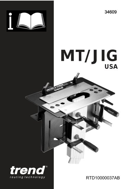
34609<strong>MT</strong>/<strong>JIG</strong><strong>USA</strong>RTD10000037AB
<strong>MT</strong>/<strong>JIG</strong> <strong>USA</strong>ItemsEnclosedx1BagBx1x1x1x6BagAx1x1x2x1x4x1x4x2x2x1x1x4x1x1For Technical Supportemail: technical@trend-usa.<strong>com</strong>-1-
<strong>MT</strong>/<strong>JIG</strong> <strong>USA</strong>Descriptionof parts1Male adjustablelever23Top plate assemblyTemplate clamp(back)123 454Long template656Set-up barTemplate clamp(front)787Female adjustablelever8910F clamp handleShort templateMain body91112Tilting back plateVertical guide101113 F clamp bar14 2-1/8” Bush121315 Threaded ring141617TemplatebushesF clamp cap161517-2-
<strong>MT</strong>/<strong>JIG</strong> <strong>USA</strong>AccessoriesSuitable router cuttersAlthough standard router bits can be used having the appropriate diameter, a set of fivelong reach straight bits with 1/4" shanks are available.Ref. SET/<strong>MT</strong>1X1/4TCDDIncludesRef. C008 C012 C015 C022 C026D Inch 1/4 5/16 3/8 1/2 5/8DDDOptional mortise cutters and tenoning bushes.Ref. C003 (3/16") diameter. Use with 1-5/16” template bush.Ref. C018 (7/16") diameter. Use with 1-1/16” template bush.Ref. C024 (9/16") diameter. Use with 15/16” template bush.Extraction Dust KitFor dust-free working, this kit allows connection to a 1-1/2” or 2-1/4” hose. The dustshield is only used when routing tenons.Ref. <strong>MT</strong>/DUSTKITAdaptorDust spoutDust shieldx4 x4 x4 x2-3-
<strong>MT</strong>/<strong>JIG</strong> <strong>USA</strong>SAFETY PRECAUTIONS■ Always switch off the power and unplug therouter when changing bits or when makingadjustments.■ Always wear protective goggles when routing.■ Wear sound protective ear muffs when routingfor long periods of time.■ Always wear a dust mask or respirator. Usedust extraction equipment whenever possible.■ Do not wear loose clothing. Make sure baggysleeves are rolled up and ties are removed.■ Always remove spanners and hex keys fromthe work piece before switching router on.■ Keep hands well clear of the router bit whenrouting.■ Avoid accidental starting of the router. Makesure the power switch is in the ‘Off’ positionbefore plugging in and connecting to theelectrical supply.■ Never leave the router unattended whenrunning. Always wait until the router <strong>com</strong>es toa <strong>com</strong>plete stop before making anyadjustments.■ Do not switch the router on with the bittouching the work piece.■ Mount the M&T Jig securely to the workbenchor workboard.■ Periodically check all bolts and levers to makesure they are secure.score the bit’s shank and create a weakness.■ It is advisable to periodically check the routercollet nut for wear.Useful Advice■ Judge your feed rate by the sound of themotor. In time, the operator will acquire a‘feel’ for the router and an efficient feed speedwill <strong>com</strong>e naturally. Too slow a feed will resultin burning of the timber.■ Apply the normal precautions as with anyelectric power tool.■ The main cause of routing machine failure isthe inclination for operators to overload them.The motto is ‘Keep the revs up’. The drop inrevolutions should not exceed, if possible,more than 20% of full running speed.■ The motor of a router is susceptible to theaccumulation of sawdust and wood chips andshould be blown out, or ‘vacuumed’ frequentlyto prevent interference with normal motorventilation.■ Refer to the Instruction Manual supplied withyour router for full details of its features andsafety information.■ Trial cuts should be made on waste materialbefore starting, to obtain familiarity with the jigand check correct selection of bit andtemplate bush.Cutter Care■ Do not drop bits or knock them against hardobjects.■ Bits should be kept clean. Resin build-upshould be removed at regular intervals withResin Cleaner ® . The use of a dry lubricantsuch as Trendicote ® PTFE spray will act as apreventative measure.■ Bit shanks should be inserted into the collet atleast 2/3 of shank length to prevent distortion.A distorted collet should be discarded, as itcan cause vibration and damage the bit’sshank.■ Do not over tighten the collet nut as this will-4-
<strong>MT</strong>/<strong>JIG</strong> <strong>USA</strong>Fixing andassembly1 Secure the tiltingback plate in its45° position withthe two hexscrews.1x442 Position the mainbody on the edgeof the workbenchor workboard anddrill four 1/8"holes 5/8"deep.3 Secure the jigwith the 4 selftappingscrewswith a No.2 Poziscrew driver.23x4Pivot bush4 Fit the three Fclamps andvertical guide asshown. Notingthat the longerhex screw withouta flange is used inconjunction withthe pivot bush.5 Return the tiltingback plate to the0° position andlock.5-5-
<strong>MT</strong>/<strong>JIG</strong> <strong>USA</strong>2Assembly ofthe Top plate1 Remove thetransit nuts anddiscard.2 Fit the two femaleadjustable levers.If fitting theoptional dustextraction kit referto opposite page.1213 Turn the top plateover so that it’sfacing up andsecure the topplate with the twomale adjustablelevers andwashers.33-6-
<strong>MT</strong>/<strong>JIG</strong> <strong>USA</strong>Fitting theoptional dustextraction kitRef. <strong>MT</strong>/DUSTKIT258mm1 Fit the dust spoutusing the 4 bolts,shake-proofwashers andnuts.39mm2 Assemble thering, fitting andbody of theadaptor ontothe 1-1/2” hose ifrequired.13 Fit the twomagnets bygently knockingthem into thefront edge on theunderside of thetop plate with awooden malletuntil flush.3x24 The dust shieldshould only befitted whencutting tenons. Itis held in place bythe magnets.✔4✗-7-
<strong>MT</strong>/<strong>JIG</strong> <strong>USA</strong>Marking outthe Tenon1 2 31 It is essential thatthe timber issquare all round.Study thedrawings for theappropriate typeof tenon tocalculate thepositions ofthe centre lineand end tenonmarks.Straight tenonCLPlan viewMarked EndCLL R2 Mark up thecentre line on theend of the firstpiece of timberusing a markinggauge.Side angled tenonEnd viewFront view3 Mark the tenonend marks usinga set square.CLCLNOTEWhen mountingtimber in the jigkeep the faceside towards thejig.LRFront angled tenonC LC LLR-8-
Cutter &Guide BushSelection1 Calculate anappropriate tenonwidth ‘X’ for thetimber width ‘W’e.g. X = 1/4” andchoose thenearestappropriate tenonwidth from thechart below.1w3ExampleTimber width of (W) 3/4”. Tenon width (X) = 1/4”2DX =<strong>MT</strong>/<strong>JIG</strong> <strong>USA</strong>XW2 For the tenonchoose theappropriate guidebush diameter ‘D’from the chartbelow forthe tenon width,e.g. D = 1 1/4".Tenon cutter willalways be Ref.C026.3 For the mortisechoose thecutter to suit thetenon width ‘X’e.g. C008. Guidebush diameterwill alwaysbe 2-1/8”.3Ref. C0262-1/8" Bush XTENONWIDTHTENONMORTISEGuide BushImperial Diameter Cutter Guide Bush CutterX D Ref Dia Ref1/4” 1-1/4” Use C0085/16” 1-3/16” Use 2-1/8” C0123/8” 1-1/8” C026 for C0151/2” 1” for all C0225/8” 7/8” all C026Other sizes possible. (Guides bushes not included with jig):3/16” 1-5/16” C0037/16” 1-1/16” C0189/16” 15/16” C024-9-
<strong>MT</strong>/<strong>JIG</strong> <strong>USA</strong>Fitting ofguidebushes-10-
<strong>MT</strong>/<strong>JIG</strong> <strong>USA</strong>Set TimberHeight1 Place set-up baron templates andpush it againsttouching clampingplate (A).DownstandSet up bar2 & 3 Placetimber up againstvertical guide (B)and raise until ittouches downstandof set-upbar.4 Tighten F clamphandles securely.1AB2443-11-
<strong>MT</strong>/<strong>JIG</strong> <strong>USA</strong>Set CentreLine1 Release levers.2 Adjust position oftop plate until thedown stand of theset-up bar alignswith the centreline.3 Tighten levers.31312 22-12-
<strong>MT</strong>/<strong>JIG</strong> <strong>USA</strong>Set Tenonlength1 Release levers.LCLR2 Align mark onset-up bar withrelevant left handtenon mark. E.g.1/4" mark if using3/4” timber.3 Slide left handtemplate to theright until itcontacts thedown stand of theset up bar.4 Tighten lever.5 Repeat procedure(1) to (4) for righthand templateusing relevantright hand markon set-up bar.31242 5L5/8"1/2"3/8"5/16"1/4"Align with tenon end& position templates5/8"1/2"3/8"5/16"1/4"5/8"1/2"3/8"5/16"1/4"Align with tenon end& position templates5/8"1/2"3/8"5/16"1/4"R-13-
<strong>MT</strong>/<strong>JIG</strong> <strong>USA</strong>RoutingProcedure11 After fitting theC026 bit andappropriatetemplate bush(see chart onpage 9), lowercutter down untilit touches end oftimber and lock offplunge of router.2 Raise and lock thedepth stop to thelength of thetenon required.3 Plunge and rout ina clockwisedirection at adepth of no morethan 3/16” inrepeated passesuntil the full depthis reached as setby the depth stop.Ensure thetemplate bush iskept firmlypressed againstthe circles of thetemplates andedges of theclamping plates.233/16"LLL-14-
<strong>MT</strong>/<strong>JIG</strong> <strong>USA</strong>Side AngledTenon1 Remove the lowerF clamp head andadjust the positionof the verticalguide as required.12 Tighten the boltwith the allen keyand refit the Fclamp head.3233 Rout the end ofthe timber parallelto the top plate orcut it at theappropriate angleon a snip-off saw.or4 Fit and clamp thetimber at thecorrect positionusing the set-upbar as shown onpage 11.Set the top plateposition as shownon page 12.Set the templatesas shown on page13.45 Set the depth ofcut and rout inincreasing depthsto <strong>com</strong>plete thetenon as shownon page 14.455-15-
<strong>MT</strong>/<strong>JIG</strong> <strong>USA</strong>Front AngledTenon1 Adjust the tiltingback plate to theposition required.2 Tighten the twobolts with the hexkey.3 Rout the end ofthe timber parallelto the top plate orcut at theappropriate angleon a snip-off saw.123 34 Fit and clamp thetimber at thecorrect positionusing the set-upbar as shown onpage 11.Set the top plateas shown on page12.4orSet the templatesas shown on page13.45 Set the depth ofcut and rout inincreasing depthsto <strong>com</strong>plete thetenon as shownon page 14.When angle isgreater than 20°move top F clampto its lower position.55-16-
<strong>MT</strong>/<strong>JIG</strong> <strong>USA</strong>Setting upfor theMortiseA1Clamp the timberfor the mortisehorizontally flushunderneath thetop plate.12 When narrowtimbers are to beused and whenthe mortise is atthe end of thetimber, the fourthF clamp can beused to secure it.The plastic capshould be fittedas shown.A3 A scrap piece oftimber can alsobe clampedvertically to givesupport and toassist in positioningof the horizontaltimber.B32B This alternativeset-up with fourthF clamp fitted inposition on theleft slot of thetilting back platecan be used.C Wider timber canbe alsoac<strong>com</strong>modatedby using the topclamp of thevertical guide.CDD Or removing thevertical guide andclamps and usinga clamp in the leftslot of the tiltingback plate.-17-
<strong>MT</strong>/<strong>JIG</strong> <strong>USA</strong>Cutting theMortise11 After fittingappropriate cutterand 2-1/8”template bush(see chart onpage 9). Lowercutter down untilit touches end oftimber and lockoff plunge ofrouter.2 Raise and lockthe depth stop tothe length of thetenon requiredplus 1/16”.3 Plunge and routbackwards andforwards at adepth of no morethan 3/16” inrepeated passesuntil the full depthis reached as setby the depth stop.2LLL + 1/16"33/16"3-18-
<strong>MT</strong>/<strong>JIG</strong> <strong>USA</strong>SquareMortise &TenonsTenons1 Release lockinglevers.2 Turn eachtemplate around.Set-up positionsof top plate andtemplates as forround tenons.See page 11-13.13 Rout in aclockwisedirection followingthe template.Mortise4 The mortise isrouted in thesame way.Square the endsof the mortisewith a suitablesize of chisel.324-19-
<strong>MT</strong>/<strong>JIG</strong> <strong>USA</strong>Doweling1 Select and fit the5/8" templatebush and astraight routercutter to suit thediameter of thedowels beingused.125/8"+ =xx2 Select the shortor long templatedepending on theformation of holesto be used.3 Mark the timbercentre line anddowel positions.Note the templatehole centres areat 1" centres.3C L4 Set-up andsecure the timberin the same wayas for mortiseand tenons. Butalign the top plateusing the centreline notches onthe templateholes. Set thecutter depth toslightly more thanhalf the dowellength.Locate the guidebush in each holeand rout theholes in a seriesof plunge cuts toprevent wastefrom packingaround the cutter.4-20-
<strong>MT</strong>/<strong>JIG</strong> <strong>USA</strong>DowelingcontinuedA1A1Position thehorizontal timbertight to theunderside of thetop plate.2 Then clamp itsecurely usinga vertical timberpiece as asupport asdescribed onpage 17 ifrequired.3 Plunge rout theholes as before.22B Use the shortplate for analternativeformation ofholes.B-21-
<strong>MT</strong>/<strong>JIG</strong> <strong>USA</strong><strong>MT</strong>/<strong>JIG</strong> <strong>USA</strong>SPARE PARTS DIAGRAM17v1.0 05/200317212328211292814138161520192019342726102218271110187126221022518223022<strong>MT</strong>/<strong>JIG</strong>41Optional AccessoryDust Extraction Kit32353536363734333940383431-22-
<strong>MT</strong>/<strong>JIG</strong> <strong>USA</strong><strong>MT</strong>/<strong>JIG</strong> <strong>USA</strong> - SPARE PARTS LIST v1.1 05/2002No. Qty. Desc. Ref.1 4 F CLAMP FOR <strong>MT</strong>/<strong>JIG</strong> WP-<strong>MT</strong>/012 1 <strong>MT</strong>/<strong>JIG</strong> SET-UP BAR <strong>USA</strong> WP-<strong>MT</strong>/02/<strong>USA</strong>3 1 LABEL TREND <strong>MT</strong>/<strong>JIG</strong> WP-<strong>MT</strong>/034 1 MAIN BODY WP-<strong>MT</strong>/045 1 VERTICAL GUIDE WP-<strong>MT</strong>/056 1 INNER BODY WP-<strong>MT</strong>/067 1 TILTING BACK PLATE WP-<strong>MT</strong>/078 1 TOP PLATE WP-<strong>MT</strong>/089 1 BACK CLAMP PLATE PACKING PIECE WP-<strong>MT</strong>/0910 3 PIVOT BUSH WP-<strong>MT</strong>/1011 1 F CLAMP SQUARE CAP WP-<strong>MT</strong>/1112 1 BACK CLAMP PLATE WP-<strong>MT</strong>/1213 1 FRONT CLAMP PLATE PACKING PIECE WP-<strong>MT</strong>/1314 1 FRONT CLAMP PLATE WP-<strong>MT</strong>/1415 1 TEMPLATE LONG WP-<strong>MT</strong>/1516 1 TEMPLATE SHORT WP-<strong>MT</strong>/1617 2 ADJUSTABLE LEVER M6 X15MM CR/KB/PK818 3 MACHINE SCREW BUTTON M6 X 16MM SOCKET WP-SCW/7519 2 ADJUSTABLE LEVER M6 FEMALE CR/KB/PK920 2 HEX NUT M6 WP-NUT/0621 2 WASHER M6 FORM C WP-WASH/1222 6 MACHINE SCREW BUTTON M6 X 12MM FLANGE SOCKET WP-SCW/7323 1 GUIDE BUSH SET BRASS IMPERIAL WP-<strong>MT</strong>/23/<strong>USA</strong>26 1 T HANDLE HEX KEY 4MM X 150MM HK/T/0427 4 SCREW NO 10 X 3/4 PAN SELF TAP POZI WP-SCW/10828 2 CLAMPING BAR SHIMS WP-<strong>MT</strong>/28DUST EXTRACTION KIT - SPARE PARTS LIST31 1 DUST SHIELD WP-<strong>MT</strong>/0332 1 DUST SPOUT WP-SRT/1633 1 MAGNET PACK 10MM X3MM PACK OF FOUR MAG/PACK/234 4 MACHINE SCREW BUTTON M6 X 12MM FLANGE SOCKET WP-SCW/7335 4 WASHER M6 INTERNAL SHAKEPROOF WP-WASH/3136 4 NUT M6 WP-<strong>MT</strong>/0637 0 HOSE ADAPTOR 58MM TO 39MM 257011 CRT/338 1 ADAPTOR BODY FOR CRT/3 WP-CRT/9739 1 ADAPTOR FITTING FOR CRT/3 WP-CRT/9840 1 ADAPTOR CLIP FOR CRT/3 WP-CRT/9941 1 MANUAL <strong>USA</strong> MANU/<strong>MT</strong>/<strong>USA</strong>-23-
<strong>MT</strong>/<strong>JIG</strong> <strong>USA</strong>IMPORTANT!For use with Plunge Routers onlyCautionCarefully read through this entire instruction Manualand the entire router Operator’s Manual before usingyour new Routasketch. Pay close attention to theSafety section and the Safety Symbols. If you useyour Routasketch properly and only for what it isintended, you will enjoy years of safe, reliable service.The operation of any router can result in foreign objects being thrown intoyour eyes, which can result in severe eye damage. Before beginning powertool operation, always wear safety glasses with side shields and a full faceshield when needed. We re<strong>com</strong>mend Wide Vision Safety Mask for useover eyeglasses or standard safety glasses with side shields. Always weareye protection.
MANU/<strong>MT</strong>/<strong>USA</strong> v1.0RECYCLABLEEmail: ______________sales@trend-usa.<strong>com</strong>WEB:____________www.trendmachinery.<strong>com</strong>© Copyright Trend 2003. No part of this publication may be reproduced, stored or transmitted in any form without prior permission.Our policy of continuous improvement means that specifications may change without notice. Trend Machinery and Cutting Toolscannot be held liable for any material rendered unusable or any form of consequential loss. E&OE® All trademarks acknowledged.