2. trocadero shower enclosure - Kohler - Kohler Co.
2. trocadero shower enclosure - Kohler - Kohler Co.
2. trocadero shower enclosure - Kohler - Kohler Co.

You also want an ePaper? Increase the reach of your titles
YUMPU automatically turns print PDFs into web optimized ePapers that Google loves.
�<br />
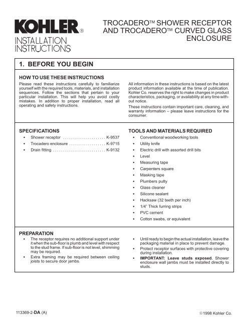
1. BEFORE YOU BEGIN<br />
HOW TO USE THESE INSTRUCTIONS<br />
Please read these instructions carefully to familiarize<br />
yourself with the required tools, materials, and installation<br />
sequences. Follow the sections that pertain to your<br />
particular installation. This will help you avoid costly<br />
mistakes. In addition to proper installation, read all<br />
operating and safety instructions.<br />
SPECIFICATIONS<br />
� Shower receptor . . . . . . . . . . . . . . . . . . . . . K-9537<br />
� Trocadero <strong>enclosure</strong> . . . . . . . . . . . . . . . . . . K-9715<br />
� Drain fitting . . . . . . . . . . . . . . . . . . . . . . . . . . K-9132<br />
PREPARATION<br />
� The receptor requires no additional support under<br />
it when the sub-floor is plumb and level with respect<br />
to the stud frame. If sub-floor is not level, shimming<br />
may be required.<br />
� Extra framing may be required between ceiling<br />
joists to secure door jambs.<br />
TROCADERO SHOWER RECEPTOR<br />
AND TROCADERO CURVED GLASS<br />
ENCLOSURE<br />
All information in these instructions is based on the latest<br />
product information available at the time of publication.<br />
<strong>Kohler</strong> <strong>Co</strong>. reserves the right to make changes in product<br />
characteristics, packaging, or availability at any time without<br />
notice.<br />
These instructions contain important care, cleaning, and<br />
warranty information – please leave instructions for the<br />
consumer.<br />
TOOLS AND MATERIALS REQUIRED<br />
� <strong>Co</strong>nventional woodworking tools<br />
� Utility knife<br />
� Electric drill with assorted drill bits<br />
� Level<br />
� Measuring tape<br />
� Carpenters square<br />
� Masking tape<br />
� Plumbers putty<br />
� Glass cleaner<br />
� Silicone sealant<br />
� Hacksaw (32 teeth per inch)<br />
� 1/4” Thick furring strips<br />
� PVC cement<br />
� <strong>Co</strong>tton swabs, or equivalent<br />
� Until ready to begin the actual installation, leave the<br />
packaging material in place to prevent damage.<br />
� Protect receptor surfaces with protective covering<br />
during installation.<br />
� IMPORTANT: Leave studs exposed. Shower<br />
<strong>enclosure</strong> wall jambs must be installed directly to<br />
studs.<br />
113369-2-DA (A)<br />
��<br />
�1998 <strong>Kohler</strong> <strong>Co</strong>.
<strong>2.</strong> TROCADERO SHOWER ENCLOSURE<br />
The Trocadero Curved Glass Shower Enclosure can be<br />
constructed with either right or left-hand door hinges, see<br />
Fig. #1 .<br />
Striker<br />
Center<br />
Jamb<br />
Showerhead<br />
Wall Jamb<br />
Side Panel<br />
Provide Structural Ceiling Support<br />
Pivot<br />
Center<br />
Jamb<br />
Door Door<br />
Wall Jamb<br />
Side Panel<br />
Receptor<br />
Jamb Bases Jamb Bases<br />
RIGHT-HAND DOOR HINGES LEFT-HAND DOOR HINGES<br />
Fig. #1<br />
Striker<br />
Center<br />
Jamb<br />
Showerhead<br />
Wall<br />
Jamb<br />
Side<br />
Panel<br />
113369-2-DA (A) 2<br />
<strong>Kohler</strong> <strong>Co</strong>., <strong>Kohler</strong>, WI
3. PRODUCT DIMENSIONS<br />
The receptor dimensions are illustrated in Fig. #2 .<br />
<strong>Kohler</strong> <strong>Co</strong>., <strong>Kohler</strong>, WI<br />
3/8” R.<br />
1-1/2”<br />
ÉÉÉÉÉÉ<br />
ÉÉÉÉÉÉ<br />
ÉÉÉÉÉÉ<br />
ÉÉÉÉÉÉ<br />
FINISHED WALL<br />
44”<br />
6-1/8” 4-5/8”<br />
The <strong>enclosure</strong> dimensions are illustrated in Fig. #3 .<br />
FINISHED WALL<br />
44”<br />
2-1/8”<br />
18-1/4”<br />
44”<br />
22-1/4”<br />
Fig. #2<br />
32”<br />
18-1/4”<br />
22-1/4”<br />
44”<br />
3-3/8” D.<br />
1/8”<br />
TOP VIEW FRONT VIEW<br />
Fig. #3<br />
72”<br />
10’-0” MAX.<br />
6’-6” MIN.<br />
3 113369-2-DA (A)
4. MOUNTING HARDWARE, JAMBS AND SEALS<br />
The hardware provided for receptor and <strong>shower</strong><br />
<strong>enclosure</strong> installation is illustrated in Fig. #4 for<br />
identification purposes.<br />
#8 x 2-1/2”<br />
Truss Head Screw<br />
2 ea. per ceiling<br />
Mounting Base<br />
Drill 1/8” hole<br />
#8 x 3/8”<br />
Soc. Setscrew<br />
2 ea. per<br />
Anti-Rotation Key<br />
3/8” x 8”<br />
Stud, Ceiling Mount<br />
1 ea. per<br />
Center Jamb<br />
Stud Mounting<br />
Jamb<br />
#8 x 1-1/2”<br />
Flat Head Screw<br />
Drill 1/8” hole<br />
#8 x 1/4”<br />
Soc. Setscrew<br />
2 ea. per Ceiling<br />
Sleeve<br />
Fig. #4<br />
#8 x 3/4”<br />
Flat Head Screw<br />
2 ea. per Top End<br />
Cap, Wall Jamb<br />
Base and Towel Bar<br />
#8 x 3/4”<br />
Soc. Setscrew<br />
1 ea. per Top Pivot<br />
Bracket<br />
Wall Jamb Wall Jamb<br />
Base<br />
Seal (Dry Side) Center Jamb Center Jamb<br />
Base<br />
Center Jamb Seal<br />
Shower (Wet)<br />
Side<br />
Pivot Seal Vinyl Filler Strip<br />
1/4” x 5/8”<br />
Flat Head Soc.<br />
Screw<br />
4 reqd.<br />
Door Hinges<br />
#8 x 2”<br />
Flat Head Screw<br />
5 ea. per Wall Jamb<br />
Wall Jamb Seal<br />
Shower (Wet)<br />
Side<br />
Latching Seal<br />
Water Deflector<br />
Assembly<br />
113369-2-DA (A) 4<br />
<strong>Kohler</strong> <strong>Co</strong>., <strong>Kohler</strong>, WI
5. PREPARATION AND NEW CONSTRUCTION<br />
The Shower Receptor is packaged in a single carton and<br />
the Curved Glass Profile Enclosure is packaged in two<br />
cartons. The cartons will fit through any standard door. Do<br />
not remove the units from cartons until ready to install<br />
them.<br />
If units must be stored outdoors before installation,<br />
protect them from the elements.<br />
Place a clean protective covering such as a drop cloth in<br />
the <strong>shower</strong> receptor to prevent damage during<br />
installation.<br />
Ensure the installation area is clean and free of all debris.<br />
If remodeling, remove all finished wall material to expose<br />
framing, and remove all floor coverings to expose<br />
subfloor.<br />
<strong>Co</strong>nstruct framing that is square vertically and<br />
horizontally in accordance with dimensions illustrated in<br />
Fig. #5. These dimensions are critical for proper<br />
installation. <strong>Co</strong>nstruct recess and plumbing accurately.<br />
Walls that do not meet these requirements or are not<br />
plumb will prohibit proper installation of the <strong>shower</strong> unit.<br />
NOTE: A variety of installations are possible.<br />
Illustrations depict suggested framing only.<br />
If grab bars are to be installed, provide backing in framing.<br />
If a firewall is required, roughing-in dimensions will have<br />
to increase according to the thickness of the firewall<br />
material.<br />
If installing this unit to a masonry wall, make provisions for<br />
plumbing connections. <strong>Co</strong>nstruct a separate frame wall a<br />
minimum of 6” from masonry wall.<br />
NOTE: Structural ceiling support must be provided for<br />
center jambs. Ceiling mounting plates must be securely<br />
fastened to framing members. Hollow wall anchors will not<br />
provide adequate support for door assembly.<br />
<strong>Kohler</strong> <strong>Co</strong>., <strong>Kohler</strong>, WI<br />
Double Studs<br />
As Shown<br />
44” 44”<br />
Fig. #5<br />
Double<br />
Studs As<br />
Shown<br />
1/4” Thick<br />
Furring Strip<br />
3/4” MIN.<br />
1-1/2” MAX.<br />
FINISHED<br />
WALL<br />
THICKNESS<br />
Structural Support<br />
Required In Ceiling<br />
Above These Center<br />
Jamb Locations<br />
5 113369-2-DA (A)
Install rough plumbing. Locate drain line and hot and cold<br />
supply lines for <strong>shower</strong> and fittings used. Follow the<br />
manufacturer’s installation instructions for proper installation.<br />
If possible, provide an access at the back of the plumbing<br />
wall in the event that servicing the supply and waste piping<br />
is necessary.<br />
Install a 2” drain pipe to extend 3/8” above the sub-floor<br />
or slab. A pocket is required in slab construction to<br />
accommodate the drain fitting.<br />
6. INSTALLATION<br />
INSTALL RECEPTOR<br />
Install drain fitting (K-9132 is recommended) to drain<br />
outlet of receptor in accordance with instructions supplied<br />
with drain fitting.<br />
Place receptor in framing. Ensure receptor is level. If<br />
shimming is required to level, place shims under wood<br />
block feet on underside of receptor. Ensure all wood block<br />
feet are supported when receptor is leveled.<br />
1-1/2” MIN.<br />
WOOD SUB-FLOOR<br />
3/8”<br />
4-5/8” DIA. MIN.<br />
CONCRETE SUB-FLOOR<br />
3/8”<br />
4-5/8” DIA. MIN.<br />
Fig. #6<br />
Fig. #7<br />
113369-2-DA (A) 6<br />
<strong>Kohler</strong> <strong>Co</strong>., <strong>Kohler</strong>, WI
After receptor is positioned snugly, install drain per drain<br />
manufacturers installation instructions. Use a non-hardening<br />
mastic sealant to achieve a watertight seal.<br />
Other installation methods are possible. For gasket<br />
connection of this drain to 2” iron or other PVC materials,<br />
consult Fernco Inc., 300 S. Dayton St., Davison, MI 48423<br />
[Phone: 1-800-521-1283] about their PSD 200 <strong>shower</strong><br />
drain connector or other suitable gasket.<br />
CAUTION: Risk of product damage. If<br />
watertight seal of drain is not achieved, receptor<br />
bottom and sub-floor may be damaged.<br />
CAUTION: Risk of product damage. Holes<br />
drilled in following steps must be countersunk to<br />
avoid cracking receptor surface layer when receptor<br />
flange is screwed in place.<br />
Using 1/8” diameter drill bit, drill holes in receptor flange<br />
at each wall stud location. <strong>Co</strong>untersink holes.<br />
Install shims behind receptor flange in areas where flange<br />
is not flush against stud.<br />
Secure receptor flange to studs using screws (not<br />
supplied).<br />
Install 1/4” thick furring strips on all wall studs above<br />
receptor flange. Furring must be full width of double studs<br />
(3-1/2”) at outer ends of receptor.<br />
<strong>Kohler</strong> <strong>Co</strong>., <strong>Kohler</strong>, WI<br />
Rubber<br />
Gasket<br />
Shower<br />
Floor<br />
Fiber Gasket<br />
Nut<br />
Lead To Top Of<br />
Nipple (Tamp<br />
Carefully)<br />
Tamp Oakum<br />
To 5/8” Depth<br />
Seal to Meet<br />
Local <strong>Co</strong>de Shower Drain<br />
Fitting<br />
4-1/2” DIA. MIN. HOLE<br />
IN SUB-FLOOR<br />
Fig. #8<br />
Fig. #9<br />
1/4” Thick<br />
Furring Strip<br />
Double<br />
Wall<br />
Studs<br />
Receptor<br />
Flange<br />
1/8” Drill<br />
Hole<br />
5/8”<br />
2” I.P.S.<br />
Drain Pipe<br />
7 113369-2-DA (A)<br />
Floor
INSTALL SHOWER ENCLOSURE<br />
Install Stud Mounting Jambs: Place center jamb base<br />
on receptor with holes in jamb base aligned with holes in<br />
receptor. Do not mount center jamb base at this time.<br />
Mark location of center hole in center jamb base onto<br />
receptor.<br />
Using carpenters square, mark a line from center jamb<br />
base hole location onto furring strip to locate centerline for<br />
stud mounting jamb.<br />
Using level or plumb line, extend mark up furring strip at<br />
least six feet. Ensure line is plumb, as line is used to align<br />
stud mounting jamb.<br />
Place wall jamb base flat on receptor against nailing<br />
flange and centered with centerline for stud mounting<br />
jamb. The wall jamb base will be used as a height gauge<br />
for installation of the stud mounting jamb.<br />
Center Jamb Base<br />
Mark Hole Location<br />
Center<br />
Jamb<br />
Base Hole<br />
Location<br />
Centerline For Stud<br />
Mounting Jamb<br />
Wall Jamb Base<br />
Fig. #10<br />
Fig. #11<br />
Fig. #12<br />
Receptor Holes<br />
Centerline For<br />
Stud Mounting<br />
Jamb<br />
Carpenters<br />
Square<br />
Nailing<br />
Flange<br />
113369-2-DA (A) 8<br />
<strong>Kohler</strong> <strong>Co</strong>., <strong>Kohler</strong>, WI
Place stud mounting jamb on wall jamb base with<br />
chamfered side against furring strip. Plumb stud mounting<br />
jamb using holes and slots in jamb and centerline marked<br />
on furring strip. Check for plumb with level. Attach stud<br />
mounting jamb to studs using four #8 x 1-1/2” flat head<br />
screws.<br />
Remove wall jamb base.<br />
Repeat procedures accompanying Fig. #10 thru Fig. #13<br />
for other stud mounting jamb.<br />
With both stud mounting jambs secured in position, stop<br />
<strong>enclosure</strong> installation until finished wall (wallboard and<br />
tile, etc.) is completed.<br />
Install wallboard horizontally with factory edge (paper<br />
bound) 1/4” maximum above the top of receptor and<br />
extending at least to the next stud beyond unit. Seal<br />
wallboard to nailing flange.<br />
Mud, tape, and finish drywall. Seal area between paper<br />
bound edge of wallboard and unit with a water-resistant<br />
sealer after wall finish has been applied.<br />
For firewall installations, use fire-resistant wallboard<br />
between the framing and 1/2” gypsum wallboard.<br />
Apply a bead of silicone sealant to both sides of stud<br />
mounting jambs at finished wall edge.<br />
<strong>Kohler</strong> <strong>Co</strong>., <strong>Kohler</strong>, WI<br />
Flat Head<br />
Screw<br />
Tile<br />
Galvanized<br />
Nails Or Screws<br />
Edge Down<br />
(Paper Bound)<br />
Fig. #13<br />
Fig. #14<br />
Stud<br />
Mounting<br />
Jamb<br />
Furring<br />
Strip<br />
Wall Studs<br />
Chamfered<br />
Side<br />
Wall Jamb Base<br />
Silicone Sealant<br />
1/4” Furring<br />
Strip<br />
2x4<br />
Framing<br />
1/2” Gypsum<br />
Wallboard<br />
1/4” MAX.<br />
Water-Resistant Sealer<br />
Between Nailing Flange<br />
And Paper Bound Edge<br />
Of Gypsum Board<br />
9 113369-2-DA (A)
Apply silicone sealant to factory-drilled center jamb screw<br />
holes on receptor.<br />
Apply a thin bead of silicone sealant under center jamb<br />
base, and install receptor using factory drilled holes and<br />
two 1-1/2” flat head screws. Apply silicone sealant over<br />
screw heads.<br />
Repeat above step, and install center jamb base at other<br />
receptor center jamb location using factory drilled holes.<br />
Locate appropriate left-hand or right-hand deflector plate<br />
against door side of striker center jamb base. Ensure<br />
deflector angle is toward inside of <strong>shower</strong>.<br />
Mark screw hole location. Remove deflector plate.<br />
CAUTION: Risk of product damage. Hole drilled<br />
in following step must be countersunk to avoid<br />
cracking receptor surface layer when deflector plate<br />
is screwed in place.<br />
CAUTION: Risk of product damage. Ensure<br />
countersink in following step is not deeper than 1/8”<br />
or a breakthrough of receptor surface layer may<br />
occur resulting in a loose fitting deflector plate.<br />
Centerpunch and drill receptor using 1/8” drill bit where<br />
previously marked. <strong>Co</strong>untersink hole using 3/16”<br />
countersink. Do not countersink deeper than 1/8”.<br />
Apply silicone sealant to hole and underside of deflector<br />
plate and install using 1-1/2” flat head screw.<br />
Determine if <strong>shower</strong> door will hinge from left or right hand<br />
side.<br />
NOTE: For purposes of these instructions, <strong>shower</strong> door<br />
is considered hinging from right hand side. See Fig. #1 .<br />
Insert lower hinge pivot pin into lower hinge pivot plate<br />
from below.<br />
1-1/2” Flat Head<br />
Screws<br />
Fig. #15<br />
Center Jamb Base<br />
Receptor<br />
Factory-Drilled Holes<br />
Fig. #16<br />
Fig. #17<br />
1-1/2” Flat<br />
Head Screw<br />
Striker Center<br />
Jamb Base<br />
Deflector Plate<br />
Lower Hinge Pin Plate<br />
Lower Hinge Pivot Pin<br />
113369-2-DA (A) 10<br />
<strong>Kohler</strong> <strong>Co</strong>., <strong>Kohler</strong>, WI
<strong>Co</strong>nstruct a cardboard template for use in aligning the<br />
lower hinge pivot plate to the center jamb base using this<br />
template.<br />
Place lower hinge pivot plate in relative mounting location<br />
against pivot center jamb base.<br />
Place template in slots of center jamb base and adjust<br />
lower hinge pin plate until hinge pin is exactly in “V” of<br />
template.<br />
Mark mounting hole locations of lower hinge pin plate onto<br />
receptor.<br />
NOTE: This ensures centerline of door pivot is aligned<br />
with stud mounting jamb. These markings are critical for<br />
proper door function.<br />
<strong>Kohler</strong> <strong>Co</strong>., <strong>Kohler</strong>, WI<br />
3/8”<br />
5/16”<br />
Hinge Pin<br />
3-1/4”<br />
TEMPLATE<br />
Fig. #18<br />
Lower Hinge<br />
Pin Plate<br />
Fig. #19<br />
Lower Hinge<br />
Pin Plate<br />
Fig. #20<br />
Pivot Center<br />
Jamb Base<br />
Pivot Center<br />
Jamb Base<br />
5/8”<br />
Template<br />
11 113369-2-DA (A)
CAUTION: Risk of product damage. Holes<br />
drilled in following steps must be countersunk to<br />
avoid cracking receptor surface layer when lower<br />
hinge plate is screwed in place.<br />
CAUTION: Risk of product damage. Ensure<br />
countersinking in following step is not deeper than<br />
1/8” or breakthrough of receptor surface layer may<br />
occur resulting a loose fitting lower hinge plate.<br />
Centerpunch and drill receptor using 1/8” drill bit where<br />
previously marked. <strong>Co</strong>untersink holes using 3/16”<br />
countersink. Do not countersink deeper than 1/8”.<br />
Apply a thin coat of silicone sealant to underside of lower<br />
hinge pin plate and screw holes. Install using 1-1/2” flat<br />
head screws.<br />
Install Wall Jambs: Apply a bead of silicone sealant to<br />
mating surface of wall jamb base where shown in<br />
Fig. #2<strong>2.</strong> Ensure sealant does not extend farther than<br />
shown on <strong>shower</strong> (wet) side of wall jamb base.<br />
Install wall jamb base to bottom end of wall jamb using<br />
3/4” flat head screws.<br />
Apply a thin coat of silicone sealant to underside of wall<br />
jamb base.<br />
Apply a bead of silicone sealant in grooves at back side<br />
of wall jamb the entire length of jamb.<br />
1-1/2” Flat<br />
Head Screws<br />
Shower (Wet) Side<br />
Wall Jamb<br />
Wall Jamb Base<br />
3/4” Flat Head Screws<br />
Fig. #21<br />
Pivot Center<br />
Jamb Base<br />
Lower Hinge Pin Plate<br />
Fig. #22<br />
Groove For<br />
Silicone Sealant<br />
Shower (Wet) Side<br />
Silicone Sealant<br />
Mating Surface<br />
113369-2-DA (A) 12<br />
<strong>Kohler</strong> <strong>Co</strong>., <strong>Kohler</strong>, WI
Slide wall jamb into stud mounting jamb and secure using<br />
five 2” flat head screws.<br />
Repeat procedures accompanying Fig. #22 and Fig. #23<br />
to install remaining wall jamb.<br />
Install Wall Jamb Seal: Slide wall jamb seal into cavity<br />
in <strong>shower</strong> (wet) side of wall jamb. Ensure seal is fully<br />
seated in wall jamb groove.<br />
Repeat procedure on other wall jamb. Seals are to extend<br />
to the receptor. Trim at top even with wall jamb.<br />
Measure distance from center jamb base on receptor to<br />
ceiling. Cut center jamb 2” shorter than this measurement.<br />
NOTE: Ensure tape measure is plumb while measuring.<br />
NOTE: Using hacksaw, cut center jamb while securely<br />
holding on a flat surface. Use square to draw cut line. Cut<br />
carefully.<br />
<strong>Kohler</strong> <strong>Co</strong>., <strong>Kohler</strong>, WI<br />
Wall Jamb<br />
2” Flat Head<br />
Screws<br />
Jamb<br />
Centerline<br />
Wall Jamb<br />
Seal<br />
Shower (Wet)<br />
Side<br />
Tile<br />
Wall Jamb<br />
Ceiling<br />
Center Jamb Base<br />
Fig. #23<br />
Tile<br />
Fig. #24<br />
Fig. #25<br />
X - 2”<br />
Wallboard<br />
Receptor<br />
Wallboard<br />
13 113369-2-DA (A)
Thread two 3/8”-16 hex nuts and one 3/8” flat washer<br />
approximately 1” onto ceiling mount stud.<br />
Place ceiling mounting base over short end of ceiling<br />
mount stud and insert other end of stud into center top of<br />
center jamb.<br />
Set center jamb into center jamb base and adjust<br />
mounting stud until ceiling mounting base is snug against<br />
ceiling support. Shift location of ceiling mounting base to<br />
accurately plumb center jamb.<br />
CAUTION: Risk of product damage. Ensure<br />
center jamb is accurately plumbed before installing<br />
ceiling mounting base.<br />
CAUTION: Risk of product damage. Ensure<br />
ceiling mounting base is installed into ceiling joist or<br />
other solid support. Toggles or wall anchors cannot<br />
be used.<br />
Accurately mark ceiling mounting base location by circling<br />
mounting base. Mark base mounting holes. Loosen<br />
ceiling stud nut. Remove base and center jamb. Drill holes<br />
using 1/8” drill.<br />
Install ceiling mounting base using two 2-1/2” truss head<br />
screws in each mounting base.<br />
Repeat procedure for remaining ceiling mounting base.<br />
Thread two 3/8” setscrews into anti-rotation key. Install<br />
assembled key into slot at bottom of center jamb used as<br />
door striker (striker center jamb). Allow key to protrude<br />
1/8” from bottom of jamb and tighten setscrews.<br />
Ceiling Mounting Base<br />
Ceiling Mount Stud<br />
Center Jamb<br />
Ceiling<br />
Mounting<br />
Base<br />
Striker Center Jamb<br />
Fig. #26<br />
Mark Outline And Holes<br />
Anti-Rotation Key<br />
Fig. #27<br />
Fig. #28<br />
Hex Nut<br />
Ceiling<br />
Mounting<br />
Base<br />
2-1/2” Truss<br />
Head Screw<br />
Setscrews<br />
1/8” Protrusion<br />
113369-2-DA (A) 14<br />
<strong>Kohler</strong> <strong>Co</strong>., <strong>Kohler</strong>, WI
Snap center jamb seal into <strong>shower</strong> side of striker center<br />
jamb.<br />
Install latching seal in opposite side of striker center jamb<br />
with thin angled wiper facing dry side of <strong>shower</strong>. Trim<br />
bottom of latching seal to fit over anti-rotation key at<br />
bottom of jamb.<br />
Install vinyl filler strips in gaps between top of seals and<br />
top of striker center jamb. Trim filler strips flush with top<br />
of jamb.<br />
Thread two #8-32 x 1/4” setscrews partially into ceiling<br />
sleeve. Apply masking tape vertically to striker center<br />
jamb to protect paint finish. Apply tape to 1’ section above<br />
latching seal. Slide sleeve over striker jamb and allow to<br />
rest on latching seal.<br />
<strong>Kohler</strong> <strong>Co</strong>., <strong>Kohler</strong>, WI<br />
Striker Center Jamb<br />
Center<br />
Jamb Seal<br />
CENTER JAMB SEAL<br />
#8-32 x 1/4”<br />
Setscrews<br />
Fig. #29<br />
Vinyl Filler Strips<br />
Fig. #30<br />
Shower (Wet) Side<br />
Latching Seal<br />
LATCHING SEAL<br />
Ceiling Sleeve<br />
Masking<br />
Tape<br />
15 113369-2-DA (A)
Insert glass side panel into striker side wall jamb.<br />
Set striker center jamb onto center jamb base. Carefully<br />
slide striker center jamb onto glass side panel.<br />
Hold in position by adjusting mounting stud until tight in<br />
ceiling mounting base. Ensure jamb is plumb. Lock stud<br />
in place by tightening upper and lower lock nuts together.<br />
Striker Side<br />
Wall Jamb<br />
Glass Side<br />
Panel<br />
Ceiling<br />
Sleeve<br />
Fig. #31<br />
Striker Center<br />
Jamb<br />
Lock Nuts<br />
Striker<br />
Center<br />
Jamb<br />
Center Jamb Base<br />
Fig. #32<br />
Glass Side Panel<br />
Ceiling Mounting<br />
Base<br />
Adjust Stud<br />
113369-2-DA (A) 16<br />
<strong>Kohler</strong> <strong>Co</strong>., <strong>Kohler</strong>, WI
Slide ceiling sleeve up to ceiling and secure by tightening<br />
setscrews. Screws should face inside of <strong>shower</strong> unit.<br />
Remove masking tape from striker center jamb.<br />
Thread two 3/8” setscrews into anti-rotation key. Install<br />
assembled key into slot at bottom of pivot center jamb.<br />
Allow key to protrude 1/8” from bottom of pivot center<br />
jamb and tighten setscrews.<br />
Snap center jamb seal into <strong>shower</strong> (wet) side of pivot<br />
center jamb.<br />
Cut vinyl fill strip 72-1/4” long. Insert into pivot jamb, door<br />
side slot. Slide down to cover anti-rotation key, flush with<br />
bottom of pivot jamb.<br />
Thread two #8-32 x 3/8” setscrews into upper hinge pivot<br />
plate. Thread pivot pin into upper hinge pivot plate until it<br />
is flush with top of plate. Lock pivot pin in place with one<br />
#8-32 x 3/4” setscrew.<br />
<strong>Kohler</strong> <strong>Co</strong>., <strong>Kohler</strong>, WI<br />
Pivot Center Jamb<br />
Fig. #33<br />
Anti-Rotation Key<br />
Fig. #34<br />
#8-32 x 3/8”<br />
Setscrews<br />
Top Pivot Pin<br />
#8-32 x 3/4”<br />
Setscrew<br />
Pivot<br />
Center<br />
Jamb<br />
Ceiling Sleeve<br />
Setscrews<br />
Protective<br />
Masking Tape<br />
Setscrews<br />
1/8” Protrusion<br />
Center<br />
Jamb Seal<br />
Shower (Wet) Side<br />
CENTER JAMB SEAL<br />
Fig. #35<br />
Fig. #36<br />
Pivot Plate<br />
17 113369-2-DA (A)
Set locking plate over setscrews installed in upper hinge<br />
pivot plate. Slide assembly into slot in pivot center jamb<br />
above vinyl filler strip.<br />
NOTE: Do not tighten screws at this time.<br />
Install one vinyl filler strip in the gap between the top of the<br />
seal and the top of the pivot center jamb. Install the other<br />
vinyl filler strip in the gap between the top pivot plate and<br />
the top of the pivot center jamb. Trim the filler strips flush<br />
with the top of jamb.<br />
Thread two #8-32 x 1/4” setscrews partially into ceiling<br />
sleeve. Apply masking tape vertically to pivot center jamb<br />
to protect paint finish. Apply tape to one foot section<br />
above seal. Slide sleeve over pivot jamb and allow to rest<br />
on pivot seal.<br />
Insert glass side panel into pivot side wall jamb.<br />
Locking Plate<br />
#8-32 x 1/4”<br />
Setscrews<br />
Glass Side Panel<br />
Locking<br />
Plate<br />
Pivot Plate<br />
Fig. #37<br />
Vinyl Filler Strips<br />
Fig. #38<br />
Fig. #39<br />
Filler Strip<br />
Grooves<br />
Pivot Center<br />
Jamb<br />
Ceiling Sleeve<br />
Masking<br />
Tape<br />
Pivot Side<br />
Wall Jamb<br />
113369-2-DA (A) 18<br />
<strong>Kohler</strong> <strong>Co</strong>., <strong>Kohler</strong>, WI
Set pivot center jamb onto center jamb base and carefully<br />
slide pivot jamb onto glass side panel.<br />
Hold in position by adjusting mounting stud until tight in<br />
ceiling mounting base.<br />
Ensure pivot center jamb is plumb. Lock in place by<br />
tightening upper and lower lock nuts together.<br />
Slide ceiling sleeve up to ceiling and secure by tightening<br />
setscrews. Screws should face inside of <strong>shower</strong> unit.<br />
Remove masking tape from pivot center jamb.<br />
Install top end cap onto pivot side and striker side wall<br />
jambs. Use two #8 x 3/4” flat head screws in each top end<br />
cap.<br />
<strong>Kohler</strong> <strong>Co</strong>., <strong>Kohler</strong>, WI<br />
Center Pivot Jamb<br />
Ceiling Sleeve<br />
Glass Side<br />
Panel<br />
Lock Nuts<br />
Pivot<br />
Center<br />
Jamb<br />
Center Jamb Base<br />
Fig. #40<br />
Fig. #41<br />
Ceiling Mounting<br />
Base<br />
Ceiling Sleeve<br />
Setscrews<br />
Mounting<br />
Stud<br />
Adjust Stud<br />
Protective<br />
Masking Tape<br />
#8 x 3/4” Flat Head Screws<br />
Fig. #42<br />
Top End Cap<br />
Wall Jamb<br />
Glass Side Panel<br />
19 113369-2-DA (A)
Position the bottom outside hinge plate on the glass door<br />
to determine the proper installation location of the<br />
deflector assembly.<br />
Apply clear silicone sealant inside the deflector channel,<br />
position the deflector channel against the hinge plate, and<br />
press firmly onto the bottom of the door. Remove any<br />
excess sealant immediately.<br />
DO NOT trim away the extra deflector material from the<br />
hinge pivot side of the door at this time.<br />
At the door opening end of the deflector assembly, trim off<br />
the extra length of deflector strip flush with the end of the<br />
deflector channel.<br />
Assemble the hinge, gaskets, and inside backing plates<br />
to the glass door with four 1/4-20 x 5/8” flat head socket<br />
screws included.<br />
When assembling the bottom inside backing plate, BE<br />
SURE the hinge plate clamps the extra length of the<br />
deflector.<br />
Slide the spacer into the handle hole in the door.<br />
Assemble the door handle to the glass door, installing the<br />
washers between the handles and glass. Lubricate the<br />
washers with glass cleaner to prevent them from<br />
bunching up during the installation of the handles.<br />
Deflector<br />
Backing Plate<br />
1/4-20 x 5/8”<br />
Flat Head<br />
Socket Screws<br />
Door Handle<br />
(Inside)<br />
Washer<br />
Spacer<br />
Washer<br />
Door<br />
Handle<br />
(Outside)<br />
Fig. #43<br />
Fig. #44<br />
113369-2-DA (A) 20<br />
<strong>Kohler</strong> <strong>Co</strong>., <strong>Kohler</strong>, WI<br />
Door<br />
Wiper<br />
Apply<br />
Sealant<br />
Bottom<br />
Door Seal<br />
Channel<br />
Gasket<br />
Top<br />
Hinge<br />
Plate<br />
Glass Door
NOTE: Due to the weight and shape of the door, two<br />
people are required to perform the door installation<br />
procedures.<br />
Position bearing washer over lower pivot pin.<br />
Lift door into position and insert lower pivot pin into hole<br />
in bottom of lower door hinge.<br />
Slide upper pivot bracket up, position door, and slide<br />
upper pivot bracket down to engage pivot pin with hole in<br />
upper door hinge.<br />
Open the door.<br />
Install the pivot seal in position, as shown. Extend beyond<br />
the bottom edge of the door glass to the top surface of the<br />
bottom hinge plate.<br />
Trim the pivot seal even with the top of the door.<br />
At the door opening end of the deflector assembly, trim the<br />
wiper so it barely touches the deflector plate.<br />
Trim the deflector as needed to clear the vertical latching<br />
seal.<br />
Carefully trim the hinge backing plate end of the deflector<br />
diagonally to match the vertical pivot seal, as shown.<br />
<strong>Kohler</strong> <strong>Co</strong>., <strong>Kohler</strong>, WI<br />
Upper Pivot Bracket<br />
Bearing Washer<br />
Pivot Seal<br />
Vertical<br />
Pivot Seal<br />
TOP<br />
BOTTOM<br />
Fig. #45<br />
Lower Door<br />
Hinge Plate<br />
Deflector<br />
(Shaded for Clarity)<br />
Fig. #46<br />
Upper Door Hinge<br />
Lower<br />
Door<br />
Hinge<br />
Bearing<br />
Washer<br />
Lower Pivot Pin<br />
Wall Jamb<br />
Shower Door<br />
Upper Door Hinge<br />
VIEWED FROM INSIDE<br />
Wiper<br />
21 113369-2-DA (A)
Slide vinyl filler up to expose setscrews in upper pivot<br />
plate. Tighten setscrews.<br />
Check door latching operation. To adjust, loosen hinge<br />
screws, shift door as required and tighten hinge screws.<br />
<strong>Co</strong>ver screw heads using supplied touch-up paint.<br />
Slide each glass side panel toward center jamb until tight<br />
against jamb.<br />
Spray glass cleaner into space between glass and inside<br />
edge of center jambs and wall jambs the entire length of<br />
each jamb.<br />
Press dry side seals into place in each center jamb first<br />
and then into each wall jamb.<br />
Dry Side<br />
Seal<br />
Glass<br />
Cleaner<br />
Vinyl Filler<br />
Setscrews<br />
VIEWED<br />
FROM<br />
INSIDE<br />
Side Panel<br />
Fig. #47<br />
Fig. #48<br />
Wet Side<br />
Seal<br />
Glass Side Panel<br />
Dry Side Seal<br />
Fig. #49<br />
Upper Pivot Plate<br />
Hinge Screws<br />
Side<br />
Panel<br />
113369-2-DA (A) 22<br />
<strong>Kohler</strong> <strong>Co</strong>., <strong>Kohler</strong>, WI
INSTALL TOWEL BAR (OPTIONAL)<br />
Measure distance (X) between wall jamb(s) and pivot or<br />
striker center jamb 30-1/2” above receptor curb.<br />
Cut each towel bar 5/32” shorter than measured distance.<br />
Use enclosed touch-up paint to cover cut end of towel<br />
bars.<br />
Insert brackets into ends of towel bars.<br />
Hold each towel bar in position 30-1/2” above receptor<br />
curb. Mark locations of screw holes. Remove towel bars.<br />
Centerpunch screw locations and drill using 1/8” drill bit.<br />
CAUTION: Drill only through outershell of jambs.<br />
Do not drill deeper or you may damage glass panel.<br />
Install towel bars using two #8 x 3/4” flat head screws for<br />
each towel bar.<br />
<strong>Co</strong>ver screw heads using supplied touch-up paint.<br />
APPLY SILICONE SEALANT<br />
Door seals are an integral part of this <strong>shower</strong> door.<br />
However, seal with a quality clear silicone sealant or<br />
equivalent is required to ensure a properly functioning,<br />
watertight unit. Seal where the glass side panel meets the<br />
receptor.<br />
The recommended procedure for sealing is as follows:<br />
Mask both edges of joint to be sealed, maintaining a joint<br />
width of 1/8” to 3/16”.<br />
Apply a uniform bead of sealant between hinge bracket<br />
and seal. Smooth bead with finger.<br />
Remove tape from sealed joint immediately after<br />
smoothing bead.<br />
Repeat for all areas to be sealed.<br />
<strong>Kohler</strong> <strong>Co</strong>., <strong>Kohler</strong>, WI<br />
30-1/2”<br />
Masking Tape<br />
1/8”-3/16<br />
Seal Locations<br />
X<br />
Fig. #50<br />
Fig. #51<br />
#8 x 3/4”<br />
Flat Head<br />
Screw<br />
23 113369-2-DA (A)
7. IMPORTANT CONSUMER INFORMATION<br />
CONSUMER RESPONSIBILITIES<br />
Your <strong>Kohler</strong> Trocadero Curved Glass Profile Shower<br />
Enclosure will remain beautiful if you take care of it. It is<br />
recommended that you replace seals, when they show<br />
signs of wear, yellowing, or are not watertight. Refer to the<br />
parts explosion in the SP3B Catalog for <strong>Kohler</strong> Service<br />
Parts.<br />
Water conditions in various parts of the country will<br />
determine any extra cleaning attention you may have to<br />
give your new <strong>shower</strong> <strong>enclosure</strong>. A simple routine of daily<br />
care will keep your <strong>shower</strong> <strong>enclosure</strong> looking like new.<br />
<strong>Kohler</strong> <strong>Co</strong>. does not recommend the use of harsh<br />
abrasive cleansers on any of its products. Harsh<br />
cleansers will damage the metal or glass finish on your<br />
<strong>shower</strong> <strong>enclosure</strong>.<br />
REQUESTING SERVICE<br />
Please take a moment to familiarize yourself with the<br />
<strong>Kohler</strong> Warranty, its benefits, and limitations. <strong>Kohler</strong> <strong>Co</strong>.<br />
and its distributors support you with one of the largest<br />
Service Networks of its type. Here’s what you need to do<br />
if you require service:<br />
FIRST: <strong>Co</strong>ntact the dealer or contractor who sold and<br />
installed the product. They should be able to<br />
solve any problems you may have.<br />
SECOND: If your dealer or contractor cannot solve the<br />
problem, they will contact or supply you with<br />
the name of the local <strong>Kohler</strong> Distributor and<br />
the:<br />
KOHLER TECHNICAL SPECIALIST<br />
THIRD: If you are unable to obtain warranty service<br />
through either your contractor or <strong>Kohler</strong> <strong>Co</strong>.<br />
distributor, please write us directly at <strong>Kohler</strong><br />
<strong>Co</strong>., Attn: Customer Service Department, 444<br />
Highland Drive, <strong>Kohler</strong>, WI 53044 U.S.A.<br />
FOURTH: Include all pertinent information regarding<br />
your claim, including a complete description of<br />
the product, model numbers, colors, finishes,<br />
and the date the product was installed.<br />
Include a description of the problem, and a<br />
photocopy of your invoice for the products<br />
involved. Also give us the name of the<br />
contractor and distributor.<br />
Apply a glass cleaner with a sponge and immediately<br />
rinse off.<br />
Please save these instructions as they contain warranty<br />
and maintenance information.<br />
For replacement parts, please contact the dealer where<br />
you purchased the <strong>shower</strong> <strong>enclosure</strong>.<br />
LIMITED ONE-YEAR WARRANTY<br />
<strong>Kohler</strong> plumbing fixtures and fittings are warranted free of<br />
manufacturing defects.<br />
<strong>Kohler</strong> <strong>Co</strong>. will, at its election repair, replace, or make<br />
appropriate adjustment where <strong>Kohler</strong> <strong>Co</strong>. inspection<br />
discloses any such defects occurring in normal usage<br />
within one year after installation. <strong>Kohler</strong> <strong>Co</strong>. is not<br />
responsible for installation costs.<br />
To obtain warranty service, contact <strong>Kohler</strong> <strong>Co</strong>. either<br />
through your Dealer or Plumbing <strong>Co</strong>ntractor or by writing<br />
<strong>Kohler</strong> <strong>Co</strong>., Attn: Customer Service Department, 444<br />
Highland Drive, <strong>Kohler</strong>, WI 53044 U.S.A., or by calling<br />
1-800-4-KOHLER from within the U.S.A.<br />
Implied warranties, including that of merchantability<br />
and fitness for a particular purpose, are expressly<br />
limited in duration to the duration of this warranty.<br />
To the extent permitted by law, <strong>Kohler</strong> <strong>Co</strong>. disclaims<br />
all implied warranties including merchantability and<br />
fitness for a particular purpose. <strong>Kohler</strong> <strong>Co</strong>. disclaims<br />
any liability for special, incidental, or consequential<br />
damages.<br />
Some states do not allow limitations on how long an<br />
implied warranty lasts or the exclusion or limitation of<br />
incidental or consequential damages, so this limitation<br />
and exclusion may not apply to you. This warranty gives<br />
you specific legal rights. You may also have rights which<br />
vary from state to state.<br />
This is our exclusive written warranty.<br />
KOHLER CO., KOHLER, WISCONSIN 53044<br />
113369-2-DA (A) 24<br />
<strong>Kohler</strong> <strong>Co</strong>., <strong>Kohler</strong>, WI