Lotem 800 II Family - Kodak
Lotem 800 II Family - Kodak
Lotem 800 II Family - Kodak
- No tags were found...

Create successful ePaper yourself
Turn your PDF publications into a flip-book with our unique Google optimized e-Paper software.
User GuideEnglish<strong>Lotem</strong> <strong>800</strong> <strong>II</strong> <strong>Family</strong>399Z3R855Awww.creo.com
<strong>Lotem</strong> <strong>800</strong> <strong>II</strong> <strong>Family</strong>User Guide
ContentsUsing This ManualScope of This Manual ............................................................................................................................. viiiConventions Used in This Manual .............................................................................................................ixFonts .................................................................................................................................................ixTerminology ......................................................................................................................................ixSymbols..............................................................................................................................................xPDF Document .........................................................................................................................................xi1 Introduction 1<strong>Lotem</strong> <strong>800</strong> <strong>II</strong> Quantum Overview .............................................................................................................. 2<strong>Lotem</strong> <strong>800</strong> <strong>II</strong> Overview.............................................................................................................................. 3Platesetter Front View............................................................................................................................... 5Platesetter Rear View................................................................................................................................ 6Typical Customer Site Configuration......................................................................................................... 7Data and Communication Flow ................................................................................................................ 8Platesetter Power Up/Shutdown ............................................................................................................... 92 PC Controller User Interface 11Overview ................................................................................................................................................ 12User Interface ......................................................................................................................................... 13Status Indicator ...................................................................................................................................... 14Operation Menu..................................................................................................................................... 15Cassette Setup................................................................................................................................. 15Routine Functions Menu .................................................................................................................. 15Utilities Menu .................................................................................................................................. 18Settings Menu ................................................................................................................................. 20Stop Button ..................................................................................................................................... 21Online Machine View ............................................................................................................................. 223 Plate Handling 25Defining Media....................................................................................................................................... 26Using the Single Cassette ....................................................................................................................... 29Releasing Cassette ........................................................................................................................... 29Loading Plates in Single Cassette ..................................................................................................... 30Inserting Cassette ............................................................................................................................ 33Defining Offline Cassette........................................................................................................................ 36Plate Geometry....................................................................................................................................... 38vii
vi<strong>Lotem</strong> <strong>800</strong> <strong>II</strong> <strong>Family</strong> User GuideA Troubleshooting 41Releasing Plates That Got Stuck.............................................................................................................. 42Plate Stuck During Centering/Punching............................................................................................ 42Plate Stuck When Loading Onto Drum............................................................................................. 43Plate Stuck When Unloading ........................................................................................................... 44Index 45
Using This ManualScope of This Manual........................................................................viiiConventions Used in This Manual ...................................................... ixPDF Document................................................................................... xi
viiiUsing This ManualScope of This ManualThe <strong>Lotem</strong> <strong>800</strong> <strong>II</strong> <strong>Family</strong> User Guide provides you with the basicinformation you need to begin production with the <strong>Lotem</strong> <strong>800</strong> <strong>II</strong>.Important: The <strong>Lotem</strong> <strong>800</strong> <strong>II</strong> <strong>Family</strong> in this manual refers to the <strong>Lotem</strong> <strong>800</strong> <strong>II</strong>and <strong>Lotem</strong> <strong>800</strong> <strong>II</strong> Quantum. Unless otherwise specified, <strong>Lotem</strong> <strong>800</strong> <strong>II</strong> refers toboth machines.Note: All screen grabs are taken from the <strong>Lotem</strong> <strong>800</strong> <strong>II</strong> unless otherwisespecified.This guide includes two main parts, as detailed below.<strong>Lotem</strong> <strong>800</strong> <strong>II</strong> platesetter and PC controller user interface• Introduction to <strong>Lotem</strong> <strong>800</strong> <strong>II</strong> platesetter• Getting started• PC controller user interface• Plate handlingIf you are running a Brisque to <strong>Lotem</strong> <strong>800</strong> <strong>II</strong> workflow, please see the Brisque to<strong>Lotem</strong> <strong>800</strong> <strong>II</strong> / <strong>Lotem</strong> Quantum <strong>Family</strong> Connectivity User Guide, 399Z1R762.If you are running a Prinergy to <strong>Lotem</strong> <strong>800</strong> <strong>II</strong> workflow please see the Prinergyto <strong>Lotem</strong> <strong>800</strong> <strong>II</strong> / <strong>Lotem</strong> Quantum <strong>Family</strong> Connectivity <strong>Family</strong> User Guide,399Z1R512B.The safety precautions that must be followed when using the<strong>Lotem</strong> <strong>800</strong> <strong>II</strong> platesetter are detailed in a separate document. See <strong>Lotem</strong><strong>800</strong> <strong>II</strong> <strong>Family</strong> Safety Precautions for User, 399Z3P854A.
Conventions Used in This ManualixConventions Used in This ManualThis section describes the fonts, terminology, and symbols used in thismanual.FontsFrutiger bold is used to refer to buttons and other items in a dialog box, filenames, folders, menu names, and menu commands.Minion Italic is used to refer to other chapters in the manual, book titles,and titles of other manuals.Frutiger is used for figure and table captions.Letter Gothic is used for messages on your computer screen and forinformation that you must type.SMALL CAPS is used for a key or key combination on your keyboard.TerminologyClearClickDouble-clickEnterRight-clickPlace the mouse pointer over the check box for thespecified option, and click the left mouse button sothat the X or check mark is removed from the checkbox.Place the mouse pointer over the specified option orbutton and press and release the left mouse button.Place the mouse pointer over the specified option orbutton and quickly press and release the left mousebutton twice.Type the information and press the ENTER or RETURNkey.Place the mouse pointer over an section of theapplication window, and then press and release theright mouse button to display the shortcut menu. Formore information about using shortcut menus, seeyour Windows documentation.
PDF DocumentxiTip: This symbol draws attention to information that can help you perform atask more quickly or easily.The reference symbol tells you that related information on the topic is availablein another Creo document.PDF DocumentThis manual is also provided in PDF (Portable Document Format). ThePDF can be found on the Documentation CD that accompanies theproduct.The PDF document can be used for online viewing and printing usingAdobe Acrobat Reader. When printing the manual, please print the entiremanual, including the copyright and disclaimer statements.
Introduction<strong>Lotem</strong> <strong>800</strong> <strong>II</strong> Quantum Overview.........................................................2<strong>Lotem</strong> <strong>800</strong> <strong>II</strong> Overview ........................................................................3Platesetter Front View .........................................................................5Platesetter Rear View ..........................................................................6Typical Customer Site Configuration....................................................7Data and Communication Flow...........................................................8Platesetter Power Up/Shutdown..........................................................9
2 Chapter 1 – Introduction<strong>Lotem</strong> <strong>800</strong> <strong>II</strong> Quantum OverviewThe state-of-the-art <strong>Lotem</strong> <strong>800</strong> <strong>II</strong> Quantum platesetter offers superbquality and high platemaking productivity of up to 25 8-up plates perhour. Creo SQUAREspot thermal imaging predictability and consistencyassures plate imaging integrity. Advanced automation, customized, inlinepunch assures accurate and repeatable notches for perfect register on press.Driven by a Brisque, the <strong>Lotem</strong> <strong>800</strong> <strong>II</strong> Quantum is for the discriminatingprinter who cannot compromise. This ultimate computer-to-plate (CTP)device meets and adapts to all your needs for efficient, continuousproduction that keeps the presses running.Creo is a pioneer of thermal imaging, the de facto standard CTPtechnology today due to its outstanding performance and quality.SQUAREspot thermal imaging maintains consistent reliable plate imagingdespite normal process variation such as changes in plate sensitivity orprocessor chemistry. This precise process control enables reliable FMscreening and artifact-free images.The fully automated platesetting sequence produces press-ready plateswithout your intervention. Plates are loaded automatically from a cassette,after automatic slip-sheet removal. The customized, inline punch systempunches plates according to the press profile selected on the workstation.Then plates are automatically mounted on the drum for imaging andunloaded directly into an optional inline processor.The <strong>Lotem</strong> <strong>800</strong> <strong>II</strong> Quantum includes:<strong>Lotem</strong> <strong>800</strong> <strong>II</strong> Quantum Plate size ranges from 457 x 381 mm (18 x 15 inch)to 1130 x 905 mm (44.5 x 35.4 inch).<strong>Lotem</strong> 850 Quantum Plate size ranges from 457 x 381 mm (18 x 15 inch)to 1160 x 950 mm (45.67 x 37.4 inch).Available in the following configurations:• Single cassette• Dual loading cassette (See DLC for <strong>Lotem</strong> <strong>800</strong> User Guide,399Z1R080B)• Multi cassette unit (See MCU for <strong>Lotem</strong> <strong>800</strong> User Guide,399Z1R092)
<strong>Lotem</strong> <strong>800</strong> <strong>II</strong> Overview 3<strong>Lotem</strong> <strong>800</strong> <strong>II</strong> OverviewThe new <strong>Lotem</strong> <strong>800</strong> <strong>II</strong> platesetter offers higher throughput, more speedoptions, and optional thermal halftone proofing.More speed options mean that printers can match throughput to theirproduction needs. The <strong>Lotem</strong> <strong>800</strong> <strong>II</strong> platesetter offers new speed optionsthat improve throughput up to 25 plates per hour. Adding the optionalthermal halftone proofing produces proofs from the same digital files,using the same screening and same halftone dot structure used to imagethe plates. The resulting proof is exactly what will be printed.<strong>Lotem</strong> <strong>800</strong> <strong>II</strong> is fully automatic, with additional speed and throughput,support for thermal halftone proofing.Available models:<strong>Lotem</strong> <strong>800</strong> <strong>II</strong> Speed - (S speed) 10 pph<strong>Lotem</strong> <strong>800</strong> <strong>II</strong> Speed - (F speed) 16 pph<strong>Lotem</strong> <strong>800</strong> <strong>II</strong> Speed - (V speed) 25 pphAll in two resolutions 2400/2540 dpiSpectrum option is available for all modelsFor more details on the Spectrum option see the <strong>Lotem</strong> <strong>800</strong> <strong>II</strong> <strong>Family</strong> withSpectrum User Guide, 399Z3R873A.The <strong>Lotem</strong> <strong>800</strong> <strong>II</strong> uses a thermal imaging head 830 nm just like any otherCreo CTP device.The <strong>Lotem</strong> <strong>800</strong> <strong>II</strong> does not support thermal compensation.<strong>Lotem</strong> <strong>800</strong> <strong>II</strong> plate size ranges from 457 x 381 mm (18 x 15 inch) to 1130 x905 mm (44.5 x 35.4 inch).
4 Chapter 1 – IntroductionThe <strong>Lotem</strong> <strong>800</strong> <strong>II</strong> is available in the following configurations:Single, dual or multi-cassette units; all plate-loading options supportautomatic slip-sheet removal; optional connectivity to In-line processors:• Single cassette unit: up to 100 plates with slip-sheets.• Dual-loading cassette: allows for two different plate sizes; the maincassette holds up to 60 plates; the upper tray holds up to 10 plates (of adifferent size) or proofing media.See the DLC for <strong>Lotem</strong> <strong>800</strong> User Guide, 399Z1R080B.• Multi-cassette unit: holds up to 500 plates in five cassettes, each with upto 100 plates. The required cassette is automatically selected accordingto the job definition. Empty cassettes can be reloaded while theplatesetter is running.See the MCU for <strong>Lotem</strong> <strong>800</strong> User Guide, 399Z1R092.
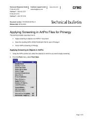
Platesetter Front View 5Platesetter Front ViewFront doorSingle cassetteRight sidedoorPaper disposaldoorPunch openingCassette entranceFigure 1: <strong>Lotem</strong> <strong>800</strong> <strong>II</strong> platesetter front view (single cassette)Note: The picture shows the single cassette. The Dual Loading Cassette (DLC) isslightly different.Single cassette – contains the plates to be exposed.Cassette entrance – where plate is loaded from the cassette into theplatesetter.Front door – door opening is controlled from PC controller monitor.Right side door – access to Electronic box and PC controller.Paper disposal door – access the Paper disposal unit and remove the slipsheets (an identical door is located on the left side).Punch opening – access the Punch container and remove the punch slugs.Opening is located below the front panel and is accessed from the bottomof the machine.
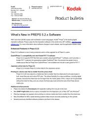
6 Chapter 1 – IntroductionPlatesetter Rear Viewon/offpushbuttonRear dooron/offpushbuttonMain circuitbreakerFigure 2: <strong>Lotem</strong> <strong>800</strong> <strong>II</strong> platesetter rear viewRear door – opening is controlled from PC controller monitor.Plate exit – through which plates are unloaded after processing.On/Off pushbuttons – to power up and shut down the platesetter.Main circuit breaker – before you power on the platesetter, make sure maincircuit breaker is on (set to “1”). For total disconnection from the mainssupply, set the main circuit breaker to “0”.
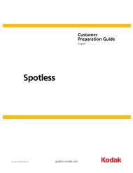
Typical Customer Site Configuration 7Typical Customer Site ConfigurationA typical customer site configuration with the <strong>Lotem</strong> <strong>800</strong> <strong>II</strong> platesetter isshown below.PrepressPlate roomMACMACBrisqueBrisquePC controllermonitorMACConveyor<strong>Lotem</strong> <strong>800</strong> <strong>II</strong>ProcessorIris ProoferImproof 750CDolev <strong>800</strong>VFigure 3: Typical configuration at customer siteNote: Figures 3 and 4 portray a typical configuration with the Brisque workflow.If you are running a Prinergy to <strong>Lotem</strong> <strong>800</strong> <strong>II</strong> workflow, please see thePrinergy to <strong>Lotem</strong> <strong>800</strong> <strong>II</strong> / <strong>Lotem</strong> Quantum <strong>Family</strong> Connectivity User Guide,399Z1R512B.The platesetter room may include:• <strong>Lotem</strong> <strong>800</strong> <strong>II</strong> platesetter• PC controller monitor; the user interface of the PC controller thatcontrols the platesetter operation.• Brisque; jobs for the <strong>Lotem</strong> <strong>800</strong> <strong>II</strong> platesetter are processed by theBrisque.
8 Chapter 1 – Introduction• Conveyor; moves the unloaded plates to the Processor.• Processor; not supplied by Creo and is intended for plates that needprocessing after expose.Note: The Plate stacker (for collecting unloaded plates) and Pre-heat oven (forplates that require heating), not supplied by Creo, are not shown in the figure.Data and Communication FlowJob data is sent from the Brisque, which is connected to the PC controller.The figure below shows the data and communication flow between theBrisque and the platesetter.PC controllermonitorData cable (TSP)<strong>Lotem</strong> <strong>800</strong> <strong>II</strong>Point to pointTSP 2TSP 1Data from prepressNetwork TCP/IP100B/TBrisqueFigure 4: Communication & data flow between platesetter & Brisque
Platesetter Power Up/Shutdown 9Platesetter Power Up/ShutdownTo power up the <strong>Lotem</strong> <strong>800</strong> <strong>II</strong> platesetter:1. Check the air pressure gauge (see figure below) in the air pressure unit.Make sure the air pressure is 6 ATM (88 psi).Figure 5: Air Pressure unit2. Make sure the Main circuit breaker is on, that is, set to “1” (see <strong>Lotem</strong><strong>800</strong> <strong>II</strong> platesetter rear view on page 6).3. At the rear panel, press out the two (2) On/Off power pushbuttons sothat they are both lit (see <strong>Lotem</strong> <strong>800</strong> <strong>II</strong> platesetter rear view on page 6).4. Press the On/Off pushbutton of the PC controller monitor.5. Wait until the Windows operating system comes up. Then doubleclickthe <strong>Lotem</strong> <strong>800</strong> icon on the PC desktop.6. Turn on the Brisque.
10 Chapter 1 – IntroductionTo turn off the <strong>Lotem</strong> <strong>800</strong> <strong>II</strong> platesetter:1. At the PC controller monitor, click the Routine Functions button.2. From the Routine Functions menu, click Shut Down.3. In the Confirm message, click Shutdown.4. From the Start menu of your Windows, click Shut Down to shutdown your computer.5. When the message It is safe to turn off your computerappears, press the On/Off power pushbutton at the platesetter rearpanel.
PC Controller UserInterfaceOverview ..........................................................................................12User Interface ...................................................................................13Status Indicator.................................................................................14Operation Menu ...............................................................................15Online Machine View........................................................................22
12 Chapter 2 – PC Controller User InterfaceOverviewThe PC controller monitor is your interface with the <strong>Lotem</strong> <strong>800</strong> <strong>II</strong>platesetter; it monitors the platesetter operation, is constantly updatedwith the machine status, and provides machine information. Theplatesetter is controlled by the PC controller located inside the platesetter;the monitor resides on a nearby table, as shown in Typical configuration atcustomer site on page 7. The job data is sent from the workstation, that isconnected to the PC controller (as shown in Communication & data flowbetween platesetter & Brisque on page 8).Figure 6: PC controller monitorNote: The platesetter image shown on the screen shows the DLC.
User Interface 13User InterfaceThe PC controller monitor is your basic working section, where theapplication indicators, buttons, popup menus and windows appear.The workflow-oriented platesetter user interface is intuitively designed,and minimal computer knowledge is required. The following featuressupport this design:• Color-coded Status indicator indicates the machine status. Forexample, if a problem occurs while you are away from the monitorchecking exposed plates, the problem indications on the screen arevisible from a distance.• Large interface indicators can be seen from a distance, so you can bealerted even when working away from the monitor.• Monitor screen is divided into functional sections, as shown in theMain window figure below.Status indicatorOperation menuInterlockindicatorMessagesectionOnline machine viewFigure 7: Main window sections (the platesetter image shows the DLC)
14 Chapter 2 – PC Controller User InterfaceStatus IndicatorThe Status indicator is fairly large and is color-coded for easyidentification. The indicator updates you on machine status even whenyou are performing tasks away from the monitor. For example, you caneasily see when the Status indicator changes to Attention.Start up (green) — machine is performing start up. All machinecomponents go to Home position.Off-line (gray) — like Ready, but you cannot expose plates or runcalibration tests; all other functions are available. After Start up and Stop,the machine automatically goes to Off-line. Click On-Line button on theRoutine Functions menu to set machine to Ready.Ready (blue) — the machine is ready for operation and in On-Line mode;you may load a plate and begin the expose job.Working (green) — the machine is busy exposing the current job. Whilethe machine is working, you can send additional jobs from the Brisque, orin case of the DLC, you can load plates in the upper tray while plates areexposed from the main.Attention (red) — the machine has stopped working and requires yourintervention, or has encountered a problem that requires servicing. Anappropriate message appears in the message section and normal operationresumes only after the problem is solved.Service (purple) — a door is open or a panel was removed (the Interlockindicator appears on the Main window) or the machine is being serviced.If a door is open, the Online machine view shows the open door.
Operation Menu 15Operation MenuThe Operation menu to the right of the Status indicator is used to accessall the operational options required when working with the platesetter PCcontroller application. The Operation menu includes the Cassette Setup,Routine Functions, Utilities and Preferences buttons used to open therelevant menus and the Stop button, as described below.Cassette SetupClick the Cassette Setup button to open the Cassette Setup menu.Whenever you need to release the cassette/upper tray, or load/unloadplates, you need to select the relevant option, as described below.Release CassetteUsed in single cassette when you need to load plates in the cassette.For details on releasing the cassette see Loading Plates in Single Cassette onpage 30.Release Tray (available only in DLC)This button is inactive in the single cassette configuration.Routine Functions MenuClick the Routine Functions button to open the Routine Functions menu.The menu includes operations that are routinely performed by the userwhen working with the machine, as described below.
16 Chapter 2 – PC Controller User InterfaceOpen Front Door1. Click to open the front door.2. The door locking mechanism is released for 30 seconds. During these30 seconds push the door slightly inward.3. The door releases. Lift the door to open it completely.When the front door is open, the safety interlocks are activated. As a result,machine systems such as drum motor and laser system do not operate. Themachine is in Service mode (Status indicator is purple) and the Interlockindicator appears below the Status indicator with the name of the opendoor.Note: You can interactively open the door by clicking on the front door inOnline machine view.Open Rear DoorThe door opening procedure is similar to opening the front door, seeabove.Loading SystemThe Loading System button that appears in the Routine Functions menu,opens a sub menu of options, including Unload Media and Restart PlateState.Unload MediaThis operation is available only when there is media on the drum and themachine is not working.In normal operation this option is not used since media unloading isautomatic. However, if the media was not loaded properly or the exposeprocess was not completed, you can manually initiate media unloading byclicking Unload Media.
Operation Menu 17Restart Plate StateWhen an error message occurs, use the Restart Plate State button. Thisoption enables you to reset the machine status.Note: Verify there are no plates stuck on the drum before you perform RestartPlate State.Offline CassetteFor single cassette, this option is relevant only if you have more than onecassette. It enables you to define the plates of the cassette that is currentlynot is use.Note: The platesetter is supplied with only one cassette, but you can purchaseadditional ones.Click Offline Cassette to open the Offline Cassette window. See DefiningOffline Cassette on page 36.MessagesClick Messages to open the Message window. When problems areencountered during machine operation, error messages are listed in theMessage window. The window automatically opens whenever an error isrecorded and the current error message is highlighted. All error messagesrecorded during the current run are listed in the window.Note: To view the full message, double-click the vertical line in Descriptionheading or manually resize the column.
18 Chapter 2 – PC Controller User InterfaceThe Message window has four buttons: Up/Down arrows for scrolling toprevious/next messages; Reset to reset the machine after solving theproblem that caused the error message (see Reset Machine, below);Help? to launch the application online help system.Reset MachineClick this button when there is a need to reset the machine. For example, aproblem that caused the machine to stop has been solved. The systemprompts you to confirm the reset. The machine then resets to Ready, Offlineor Working status, depending on the status prior to the reset.Note: Reset machine on the Routine Functions menu is the same as theReset button in the Message window.On-lineWhen the Status indicator is Off-line, you cannot expose plates.To expose plates, click On-line and wait until the machine resets to Ready.Shut DownUse this option for normal machine shutdown. See Platesetter Power Up/Shutdown on page 9.Utilities MenuClick the Utilities button to open the Utilities menu. The menu options aredescribed below.Expose ParamsThe Expose Info window lists important expose-related machineparameters. You may open this window anytime before or duringexposure.Log FilesFour windows open: Machine task list, two Log message windows (forservice usage) and Expose queue list (data sent from the Brisque).
Operation Menu 19Machine InfoPC controller software version.HardwareLists the machine hardware parts.DiagnosticsNot yet available.Remote SupportClick the Remote Support button, the following window appears:Confirmation will allow the service engineer to work by remote with theuser.
20 Chapter 2 – PC Controller User InterfaceUsersDefines the type of user (some application settings and preferences areavailable only for service and R&D). Click Users to open the Define Userwindow. In the window, choose user type – user, service or R&D. Thenenter your password and click OK.Settings MenuClick the Setting button to open the Settings menu. The menu options aredescribed below.Media DefinitionsMedia definitions is used to define the type of plates you will be using (theplate must be defined before it is loaded). This option is also used to editthe parameters of existing plates or to delete plates you will no longer use.For details see Defining Media on page 26.
Operation Menu 21Cassette ConfigurationCassette Configuration is available for all new single cassettes. This optionenables the platesetter to automatically recognize the cassette when it isinserted. In addition, you can assign user-defined names to the cassettes.These names will replace the default system names. For details, seeInserting Cassette on page 33.Note: The Cassette Configuration window will automatically open the cassettewhen it is used for the first time. However, you can always open the window byselecting Cassette Configuration from the Settings menu.PreferencesPreferences is used to define various settings. In the Preferences window,you can set the following:Units — choose cm or inch to set units of measurement for allmeasurements, such as plate dimensions and thickness.Language — only English is implemented.Stop ButtonThe Stop button on Operation menu is used in case of an emergency stop.The drum and all the machine operations are immediately stopped, andthe plate remains in its current position.
22 Chapter 2 – PC Controller User InterfaceOnline Machine ViewThe Online machine view shows the platesetter during operation; itenables you to see a simulation of machine operation. The main featuresare described below.Operational stageWhen the machine is in Working status, you can identify the currentoperational stage. You can see the plate loading onto the drum and therotating drum. The remaining process time is indicated on the Progressindicator.Cassette contentIn single cassette, the cassette content - plate type and quantity - is alwaysdisplayed above the cassette in the Online machine view, as shown below.Figure 8: Single cassette content windowInterlock indicationWhen a door is open or a panel is removed, a safety interlock is activated.The Status indicator shows Service (purple) and the Interlock indicatorappears below it with the name of the activated safety interlock.For details on safety interlocks see <strong>Lotem</strong> <strong>800</strong> <strong>II</strong> <strong>Family</strong> Safety Precautions forUser, 399Z3P854A.
Online Machine View 23Figure 9: Main screen with cassette released, Service status, interlock indicatoractivatedAttentionWhen the machine status is Attention, the Online machine view may givesome indication as to the cause of the problem. For example, if a plate isstuck inside the machine.Perform interactive operationsYou can interactively release the cassette from the platesetter by clicking onthe cassette (only for single cassette and DLC). You can also open the frontor rear door by clicking on the relevant door on the Online machine view.(This is the same as using Open Front door and Open Rear door on theRoutine Functions menu.)Note: When you move the cursor on the door or the cassette it becomes green.See the figure on page 24.
24 Chapter 2 – PC Controller User InterfaceFigure 10: Main screen with front door green when the cursor moves on it
Plate HandlingDefining Media .................................................................................26Using the Single Cassette..................................................................29Defining Offline Cassette ..................................................................36Plate Geometry .................................................................................38
26 Chapter 3 – Plate HandlingDefining MediaThe media exposed by the <strong>Lotem</strong> <strong>800</strong> <strong>II</strong> platesetter must be defined beforethe media are loaded into the platesetter.Plate specifications for the <strong>Lotem</strong> <strong>800</strong> <strong>II</strong> platesetter:Size Minimum size Maximum size<strong>Lotem</strong> <strong>800</strong> <strong>II</strong> / 457 x 381 mm 1130 x 905 mm<strong>Lotem</strong> <strong>800</strong> <strong>II</strong>Quantum<strong>Lotem</strong> 850Quantum457 x 381 mm 1160 x 950 mmQuantity 0.2 mm plates 0.3 mm platesSingle cassette 130 100DLC, main105 70compartmentDLC, uppertray15 10
Defining Media 27To define media:1. From the Settings menu, select Media Definitions to open the MediaDefinition window. In the Media list you can see the media that havealready been defined.Note: The plate names in above window are only examples. The platesettersupports plates of various specifications from various vendors, and Creo does notpromote plates of specific companies.2. Click New.3. In the TH Name box, select TH name from the existing pre-definedmedia.4. In the Class box, select the media type.5. In the Name box, assign the plate a name, for example plate type orthe user name.6. From the Manufacturer List Box, select the manufacturer name.7. From the Type box List Box, select positive or negative.8. From the Height List Box, select the media height or type a value inmillimeters.
28 Chapter 3 – Plate Handling9. From the Width list box, select the media width or type a value inmillimeters.10. From the Thickness box, type the media thickness. You must verify theplate thickness with a micrometer. it should range: 0.15 - 0.3 mm.11. Click Save to save the new media. The name of the new media appearsin the Media list.Repeat the above procedure to define all the plates you intend to use.Note: The media names will also appear in the Current Cassette window onpage 35 and Offline Cassette window on page 37.To modify the parameters of existing media:1. From the Media list, select the media whose parameters you want toedit. The selected media parameters appear under Media Parameters.2. Edit the parameters as explained in To define media: on page 27.3. Click Save to save the new parameters.To delete the parameters of existing media:‣ From the Media List, select the requested media and click Delete.Note: To change the media name, you must first Delete the media.Then clickNew to configure it again.
Using the Single Cassette 29Using the Single CassetteReleasing CassetteLoading plates into the single cassette requires:• Releasing cassette from platesetter• Loading plates into cassette• Inserting cassette into platesetterYou need to release the cassette in the following cases:• To add identical plates to the cassette currently in the platesetter• To load different plates in the cassette currently in the platesetter• To insert a new cassetteNote: The cassette pins remain depressed whenever a cassette is not loaded,providing that both upper doors are closed and the loading system has not beenmoved.1. Click Cassette Setup on the Main Operations menu. Then from themenu that opens, select Release Cassette, or:click on the cassette on the Online machine view. The Online machineview will then show the cassette outside the machine.Figure 11: Main window showing the released cassette
30 Chapter 3 – Plate Handling2. The pins that lock the cassette inside the platesetter are released. Youwill hear a tone indicating that the cassette lock is released.3. Go to the front of the cassette, and with your foot release the stoppersthat lock the wheels of the cassette.4. Pull out the cassette.5. Roll the cassette to the location of the plates.Loading Plates in Single CassetteTo load plates in the cassette (see figure on page 32):Note: The cassette should be near the location of the plates (the plates are heavyand you want to avoid carrying them).1. Open the two side latches of the cassette to open the cassette cover.2. Release the three plate guides (left, right and back guide), by openingthe knob of each guide.3. If the plates to be loaded are not the same size as the plates previouslyloaded, do the following:push the side guides outwards toward the cassette sides. Note thatwhen you move one side guide, the other side guide moves as well.Push the back guide toward the back edge of the cassette.Note: If the new plates are the same size as the plates previously loaded, youneed to move only the side plate guides to avoid scratching the plates.4. To prevent scratches on the bottom plate, the bottom plate should beplaced on a piece of cardboard and not directly in the cassette. If yourplates are not packaged with a bottom protective cardboard, place asuitable piece of cardboard (same size as plates) in the cassette.5. Place the plates, emulsion side down, inside the cassette on thebottom cardboard.Note: You should wear protective gloves to protect your hands from the sharpplate edges and to avoid leaving fingerprints on the plates.
Using the Single Cassette 316. If you are loading several packages of plates, make sure there is nocardboard between the different packages (cardboard is required onlyunder the bottom plate in the cassette).7. Move the left or right plate guide toward the plates, until the roundedtip of the side guide touches the plate edge (this prevents the sideguides from forcefully pressing against the plate). The guidesautomatically center the plates in the cassette (to ensure that whenloaded onto the drum, the plate is aligned with drum center).Note: If more than 25 plates are loaded, you need to use your hands to movethe plates and align them with the plate guides.8. Move the back plate guide toward the plate edge. Make sure the guideonly slightly touches the plate edge.9. Close and tighten the knobs of the three plate guides.10. Close the cassette cover and lock the two latches.
32 Chapter 3 – Plate HandlingFigure 12: Loading plates in cassette
Using the Single Cassette 33Inserting CassetteAfter the plates are loaded in the cassette, the cassette is ready to be insertedinto the platesetter.1. At the main window, make sure the cassette in the Online machineview shows the cassette outside the platesetter, the machine status isService and the interlock indicator informs that the cassette interlockis open (see the figure on page 29). This is important because you wantto be certain that the pins at the cassette entrance are depressed (if thepins are up you cannot insert the cassette).2. Roll the cassette to the front side of the platesetter, opposite thecassette entrance.3. Rotate the cassette so that it is positioned at an angle and push onecorner into the cassette entrance. Then rotate the cassette until it isparallel to the platesetter and push the other corner into the cassetteentrance.Figure 13: Inserting the cassette4. Push the cassette into the cassette entrance until you hear that it islocked inside. Try to pull out the cassette to verify that it is properlylocked. If it is not locked, push it in until it locks.When the cassette is used for the first time:If the cassette is used for the first time, the Cassette Configuration windowautomatically opens.
34 Chapter 3 – Plate HandlingFigure 14: Cassette Configuration for cassette used for the first time5. Select the cassette Type from the List Box. For single cassette, chooseSingle Load.Note: Another Type option is the DLC (see DLC for <strong>Lotem</strong> <strong>800</strong> User Guide,399Z1R080B).6. Enter a cassette name of your choice in the Name box.Note: If you do not enter a name, the system will assign a default name.See the window example below.Figure 15: Cassette Configuration window after defining single cassette7. Click OK to confirm the window setting.
Using the Single Cassette 35The Current cassette window appears.Figure 16: Current Cassette windowNote: The plate name in above window is only an example. The platesettersupports plates of various specifications from various vendors, and Creo does notpromote specific companies’ plates.The Cassette Name is automatically listed, as defined previously in theCassette Configuration window. If you used the Offline Cassette option,proceed to step 10. Otherwise, proceed to step 8.Note: Offline Cassette is described on page 36.8. From the Name box, select the name of your plate. Available platenames are the plates defined in the Media Definition window. ThePos/Neg, size, thickness for the selected plate appear in the window.9. In the Quantity box, type the number of plates in the cassette.
36 Chapter 3 – Plate Handling10. When the Current Cassette window setting is correct, click OK toconfirm. You may begin exposing the plates.When the cassette is used the 2nd time (and all subsequent times):After the cassette is defined in the Cassette Configuration window the firsttime it is used, this window will not open again. Instead, the CurrentCassette window will automatically open, as shown on the previous page.Note: You can always open the Cassette Configuration window from theSettings menu.Defining Offline CassetteOffline Cassette enables you to define the plates of the cassette that iscurrently not in use, and is available for all cassette configurations. The<strong>Lotem</strong> <strong>800</strong> <strong>II</strong> is supplied with one cassette, but you can purchase additionalcassettes.Note: For single cassette, this procedure is relevant only if you have more thanone cassette.Defining plates before the cassette or tray are actually inserted into themachine saves operation time. While the machine is processing plates fromone source (such as, another cassette), you can define the plates in anothersource. Later, when the second source is inserted, the Current Cassettewindow will open with the correct plate name and quantity.
Defining Offline Cassette 37To define offline cassette:1. From the Routine Functions menu, select Offline cassette. The OfflineCassette window opens.Figure 17: Offline Cassette window (for DLC main)2. From the Cassette Name select the cassette name. If you changed thedefault cassette name, the new names will appear in the List Box.Otherwise, the default names will appear (001_Main in the windowapplies to the main compartment of the DLC).Note: To change the default cassette names, use Cassette Configurationunder the Preferences menu. See page 34.
38 Chapter 3 – Plate Handling3. From the Name box, select your plate name. Available names are theplates defined in the Media Definition window. The plate parameterswill then appear for the selected plates.4. In the Quantity box, type the number of plates in the cassette.5. Click Apply to confirm the window setting.When this single cassette is inserted into the machine, the Current Cassettewindow will automatically open with the above setting.Plate GeometryThis section describes aspects of the plate geometry and image area. Theseaspects will help you plan for the plate exposure process and define thecorrect settings for your press and plate, and for your image offset.Head margin – defined on the Brisque, as one of the Press formatparameters. It defines the distance from the plate edge until the beginningof the layout or the exposed image. This parameter is also known asleading edge to print.
Plate Geometry 39Tail margin – defined on the Brisque as one of the Press format parameters.It defines the distance from the back edge of the plate to the edge of the fileor layout.H (height) – plate height (around the drum).W (width) – plate width (along the drum width).In a negative exposure of a positive working plate, there is always anemulsion area on the plate that is not exposed, therefore emulsion areasremain. The size of these areas is determined as follows:• At the head, the area is equal to the width of the plate and at a height ofup to 6 mm.• At the tail, the area is equal to the width of the plate and at a height ofup to 6 mm.The image alignment is determined by the Alignment, as defined in thePlate Expose window on the Brisque or in the Output Process Plan in thePrinergy. For details, see Brisque to <strong>Lotem</strong> <strong>800</strong> <strong>II</strong> / <strong>Lotem</strong> Quantum <strong>Family</strong>Connectivity User Guide, 399Z1R762 or Prinergy to <strong>Lotem</strong> <strong>800</strong> <strong>II</strong> / <strong>Lotem</strong>Quantum <strong>Family</strong> Connectivity User Guide, 399Z1R512B.
TroubleshootingReleasing Plates That Got Stuck ........................................................42
42 Appendix A – TroubleshootingReleasing Plates That Got StuckThis section describes how to remove a plate that might get stuck inside theplatesetter. Special precautions are required when performing thisprocedure.WARNING: The plate edges are sharp so the plate should not be handled withbare hands. Wear gloves before attempting to release a plate.Plate Stuck During Centering/PunchingPlates may get stuck during the plate centering and punching stages,during plate loading on the drum or during plate unloading.If one of these stages fails as a result of plate jamming, an appropriate errormessage appears in the Message window and the status shows Attention(red). The error message provides an indication where the jammed plate islocated, and the necessary steps to release the plate (depending on the platelocation).Important notes regarding released plates:• It is recommended to release the entire plate as one piece; do notattempt to cut the plate.• Released plates must be disposed; you may not re-use the plate.1. Click Open Front door on the Routine Functions menu, or click on thefront door on the Online machine view. Opening the door activatesthe laser and drum interlocks.2. The front door locking mechanism is released for 30 seconds. Duringthese 30 seconds, press the door slightly downward.3. The door is released. Lift the door upward to open it completely.4. Look inside the machine to locate the plate.5. Wear protective gloves and grab the top edge of the plate (edge closestto the drum) to pull out the plate.6. Dispose the released plate.7. Reset the machine to Home position by clicking Reset Machine on theRoutine Functions menu.
Releasing Plates That Got Stuck 43The status indicator shows Ready (blue) or Working (green) and the nextplate is loaded, or Off-line (gray) if there are no more plates to expose.Plate Stuck When Loading Onto DrumWhen the plate is loaded onto the drum, the tail gripper test may fail.1. Click Open Rear Door on the Routine Functions menu, or click on therear door on the Online machine view. Opening the door activates thelaser and drum interlocks.2. Move the tail grippers away from the plate.3. Carefully rotate the drum until you can see the head gripper.4. Press the head gripper clamps one by one to manually activate thehead gripper.5. Now that the plate is released, you can remove the plate: wearprotective gloves and pull out the plate.6. Dispose the plate.7. In the Hardware window, deactivate the head gripper.8. Move the tail grippers to pre-load position.9. Perform a machine reset.10. In the Hardware window, open the Loading system directory anddouble-click on Loading system. The Loading system window opens.11. In the Loading System window, click Restart Plate State.12. Then click the Pre-load button (in the same window) to move the tailgripper to the correct position according to the defined plate size.The status indicator shows Ready (blue).
44 Appendix A – TroubleshootingPlate Stuck When Unloading1. Click Open Rear door on the Routine Functions menu, or click on therear door on the Online machine view.2. The Rear door locking mechanism is released for 30 seconds. Duringthese 30 seconds, press the door slightly downward.3. The door is released. Lift the door upward to open it completely.4. Look inside the machine to locate the plate.5. Pull out the plate while wearing protective gloves.6. Perform a machine reset.7. Dispose the plate.The status indicator shows Ready (blue) or Working (green) or Off-line(gray).
IndexAActive interlock name, 22Air pressure unitgauge, 9Attention status, 14, 23Attention symbol, xBBrisque, 7CCassetteloading in machine, 33loading plates, 30opening, 30Cassette Configuration, 21Cassette entrance, 33Cassette pins, 29, 33Caution symbol, xconventions used in the manual, ixConveyor, 8Current cassette window, 35Customer site configuration, 7DDanger symbol, xData & communication flow, 8Define user window, 20Diagnostics, 19EEmergency stop, 21Emulsion area, 39Error messages, 17Expose Info window, 18Expose Params, 18Expose queue list, 18Exposed image area, 38FFonts used in the manual, ixHHardware, 19Home position, 42Iimportant symbol, xInteractive operations, 23Interlock indication, 22Interlock indicator, 14JJammed platesdisposal, 42LLanguage, 21Leading edge to print, 38Loading plates, 30Loading System, 16Log Files, 18Log message window, 18<strong>Lotem</strong> <strong>800</strong> <strong>II</strong>cassette loading, 33power up, 9shutdown, 10MMachine hardware, 19Machine Info, 19Machine parameters, 18Machine reset, 18Machine simulation, 22Machine status, 14Machine task list, 18Main circuit breaker, 6Main window, 13active door/cassette, 23MediaDefinition, 20, 27parameters, 28Message window, 17Messages, 17NNote symbol, xOOffline Cassette, 17Off-line status, 14, 18On/Off pushbuttons, 6On-line button, 18Online help, 18Online machine view, 22Open doors interactively, 23Open front door, 16interactively, 23Open rear door, 16interactively, 23Operation Menucassette setup button, 15Operation menu, 15release cassette button, 15release tray button, 15PPC controllersw version, 19user interface, 13PC controller monitor, 7, 12Plate Definition window, 27Plate exit, 6Plate Expose on Brisque, 39Plate geometry, 38Plate guides, 30Plate height, 39Plate stacker, 8Plate width, 39Platesdeleting, 28in the cassette, 30number in cassette, 35, 38specifications, 26Plates off-linedefining, 36Plates that get stuck, 42Platesetteronline view, 22
46 <strong>Lotem</strong> <strong>800</strong> <strong>II</strong> <strong>Family</strong> User Guidepower up, 9shutdown, 10Preferences, 21Pre-heat oven, 8Press format parameters, 39Process time indication, 22Processor, 8Progress indicator, 22RReady status, 14reference symbol, xiRelease cassetteinteractively, 23procedure, 29Reset machine, 18Routine Functions, 15Routine functionsloading system icon, 16messages, 17offline cassette, 17Open front door, 16open rear door, 16Restart plate state, 17unload media, 16UUnits of measurement, 21Unload media, 16Unload plate, 16User interfacefeatures, 13main window, 13User type, 20Users, 20Utilities, 18WWorking status, 14SSafety interlocks, 22Service mode, 16Service status, 14, 22Setting, 20Setup Tables, 19Shut down, 18Single cassetteloading plates, 29releasing cassette, 29Start up status, 14Status indicator, 14Stop button, 21symbols used in the manual, xTTail gripper failure, 43Terminology used in the manual, ixTip symbol, xi