Hitachi - CR12V - Recip Saw / Saber Saw - Carey Tool
Hitachi - CR12V - Recip Saw / Saber Saw - Carey Tool
Hitachi - CR12V - Recip Saw / Saber Saw - Carey Tool
- No tags were found...

Create successful ePaper yourself
Turn your PDF publications into a flip-book with our unique Google optimized e-Paper software.
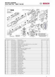
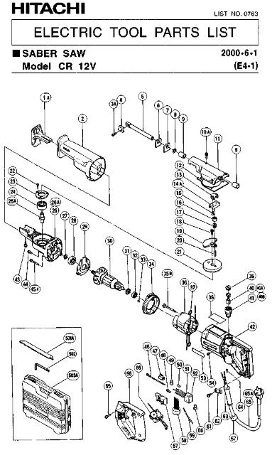
MODELS CR 12V/CR 121. NOTES ON DISASSEMBLY AND REASSEMBLY:The circled numbers in the descriptions below correspond to the item numbers in the Parts Lists and explodedassembly diagrams.1-1. Diassembly:(1) Disassembly of the Upper Cover Ass’y 11 :After removing the Base 1 and the <strong>Saw</strong> Blade 501 , take off the Insulation Cover 2 by pulling itforward (toward the blade mounting end). Then, shift the Plunger 5 forward (toward the blademounting end) and loosen the four M5 x 16 Machine Screws 10 which secure the Upper Cover Ass’y11 . The Upper Cover A’ssy can then be removed by lifting it upwards.(2) Disassembly of the Plunger 5 from the Upper Cover Ass’y 11 :First remove the two M5 x 12 Hexagon Socket Flat Hd. Screws 15 which secure the Connector 14 .As these are seal lock screws which are secured by an adhesive agent, it may be necessary to heat theUpper Cover Ass’y 11 to a temperature of 100°C - 150°C to permit their removal. The Plunger5 can then be removed from the Upper Cover Ass’y 11 by pulling it out toward the front (towardthe blade mounting end) .(3) Disassembly of the Gear Cover 26 from the Housing Ass’y 42 :Remove the Brush Caps 39 , and take out the Carbon Brushes 40 . Next, remove the four D5 x 35Tapping Screws 45 . The Gear Cover 26 (together with the Armature 30 and ralated parts) can thenbe removed from the Housing Ass’y 42 .(4) Disassembly of the Armature 30 from the Gear Cover 26 :Remove the three M4 x 12 Machine Screws 44 . The Armature 30 (together with the Bearing Cover29 ) can the be removed from the Gear Cover 26 .(5) Disassembly of the Bearing Cover 29 from the Armature 30 :First, remove the C-Type Retaining Ring 27 from the Armature 30 . Then, as illustrated in Fig.5,mount the Armature on a J-173 Puller Attachment (special repair tool, Code No. 970954) , andsecure it in position with the three M4 x 12 Machine Screws 44 . Next, support the J-173 PullerAttachment with an appropriate tubular jig (inner diameter of 80 mm or more, outer diameter of130 mm of less) , and push down on the Pinion end of the Armature with a hand press to loosen andremove the Armature 30 from the Bearing Cover 29 .(6) Disassembly of the Gear Ass’y 21 andSpindle 25 from the Gear Cover 26 :M4 x 12 Machine Screws 44Remove the M6 x 16 Hexagon Socket FlatHd. Screw 18 which secures the Balance (3 pcs)Weight 19 , and remove the Balance Weightfrom the Gear Cover 26 . As this screwis a seal lock screw which is secured by anTubular Jigadhesive agent, it may be necessary to heatInner Dia: 80mm or morethe Gear Cover 26 to a temperature of Outer Dia: 130mm or less100°C - 150°C to permit its removal. Then,through the hole provided in the Gear Ass’y21 , remove the three M4 x 12 Flat Hd.Screws 22 . The Gear Ass’y 21 , BearingCover (A) 23 , 6202VVCM Ball Bearing 24Armature 30and Spindle 25 can be taken out of theGear Cover 26 in a single body. Finally,push down on the gear-side end of the Spindleto separate the Spindle 25 from the Gear Ass’y 21 . .PushFig. 5Bearing Cover 29J-173 PullerAttachment− 1 −
1-2. Reassembly:Reassembly can be accomplished by following the disassembly procedures in reverse. However, specialattention should be given to the following items.(1) Insert 30 g of grease (Molub-Alloy #1) into both the Gear Cover and Upper Cover. Also apply aliberal amount of grease to the following parts:The 6202VVCM Ball Bearing 24 in the Gear Cover 26 , the Neelde Roller 17 , Connecting Piece(A) 16 , the teeth portion of the Gear Ass’y 21 , the inside of the Connector 14 , the Connectorsliding portion in the Upper Cover Ass’y 11 , and the metal sliding portion of the Plunger 5 .(2) When pressure fitting the Gear Ass’y 21 onto the Spindle 25 , do not forget to assemble BearingCover (A) 23 .(3) Prior to reinstalling the Plunger 5 into the Upper Cover Ass’y 11 , ensure without fail that the FeltPacking 7 , Packing Washer 6 and 1AP12 O-Ring 8 are properly assembled.(4) The screws listed below are seal lock screws. Once they have been removed, they must be treatedwith Cemedine 1500 or ThreeBond TB2410 adhesive as indicated if they are to be used again.z#M6 x 16 Hexagon Socket Flat Hd. Screws 1811111111111111111111111111111111111111111111 Cemedine 1500z#M5 x 12 Hexagon Socket Flat Hd. Screws 15z#M5 x 16 Machine Screws 10z#M4 x 12 Machine Screws 44 ..................................................................... ThreeBond TB2410z#M4 x 12 Flat Hd. Screws 22(5) When reassembling the Upper Cover Ass’y 11 onto the Gear Cover 26 , do not forget to assemblethe Seal Packing 12 .(6) When reassembling the Handle Cover 56 onto the Housing Ass’y 42 , ensure without fail that noneof the leadwires are pinched between them.(7) Tightening Torques:D4 Tapping Screw ........................................................................... 20 ± 5kgf-cm (17.4 ± 4.34 in-lb)D5 Tapping Screw ........................................................................... 30 ± 5kgf-cm (26 ± 4.34 in-lb)M4 Machine Screw, Flat Hd. Screw ................................................ 15 - 20kgf-cm (13.02 ± 17.4 in-lb)M5 Machine Screw .......................................................................... 30 - 55kgf-cm (26 ± 47.75 in-lb)M5 Hexagon Socket Flat Hd. Screw ................................................ 50 - 60kgf-cm (43.41 ± 52.09 in-lb)M6 Hexagon Socket Flat Hd. Screw ................................................ 80 ± 10kgf-cm (69.45 ± 8.68 in-lb)− 2 −
1-3. Wiring Diagram and Internal Wire Arrangements:(1) Model <strong>CR12V</strong>For European countries:BlackRedTriggerSwitchArmatureControlCircuitNoise SuppressorCordStatorAss’yWhite or BlueFig. 6For N.Z.:BlackWhiteBlackRedTriggerSwitchControlArmatureCircuitNoise SuppressorChokeCoilCordStatorAss’yBlueBlackWhiteFig.7− 3 −
For Australia:BlackRedTriggerSwitchControlCircuitArmatureCordStatorAss’yBlueFig. 8For other countries:BlackRedTriggerSwitchControlCircuitArmatureCordStatorAss’yWhite or BlueFig. 9− 4 −
For European countries:Trigger SwitchNoise SuppressorControl CircuitFig. 10For N.Z.:Trigger SwitchNoise SuppressorControl CircuitChoke CoilFig. 11− 5 −
(2) Model CR12For European contries:TriggerSwitchArmatureNoise SuppressorCordStatorAss’yFig 12For N.Z.:BlackWhiteTriggerSwitchArmatureNoise SuppressorChokeCoilCordStatorAss’yFig 13BlackWhiteFor Australia:TriggerSwitchArmatureCordStatorAss’yFig 14− 6 −
For other countriesTriggerSwitchArmatureCordStatorAss’yFig. 15For European countries:Trigger SwitchNoise SuppressorFig. 16− 7 −
For N.Z.:Trigger SwitchNoise SuppressorChoke CoilFig. 171-4. Remaingin Reassembly:Remaining reassembly can be accomplished by following the disassembly procedures in reverse.1-5. Insulation Tests:On completion of disassembly and repair, carefully measure the insulation resistance and conductdielectric strength test.Insulation Resistance: 7MΩ or more with 500V DC Megohm TesterDielectric Strength: AC 4000V/1 minute, with no abnormalities ................... 220V - 240V(and 110V for U.K. products)AC 2500V/1 minute, with no abnormalities ................... 110V - 127V(except U.K. products)− 8 −