ShadingSo far, the polygons out of which our animated objects have been built have hadcolors of fixed intensities. For example, a face of a cube might be blue, or green, orwhite, but whatever color it is, that color never brightens or dims. Fixed colors areeasy to implement, buthey don’t make for very realistic animation. In the real world,the intensity of the color of a surface varies depending on how brightly it is illuminated.The ability to simulate the illumination of a surface, or shading, is the nextfeature we’ll add to X-Sharp.The overall shading of an object is the sum of several types of shading components.Ambient shadingis illumination by what you might think of as background light, lightthat’s coming from all directions; all surfaces are equally illuminated by ambientlight, regardless of their orientation. Directed lighting, producing diffuse shading, isillumination from one or more specific light sources. Directed light has a specificdirection, and the angle at which it strikes a surface determines how brightly it lightsthat surface. Specular reJection is the tendency of a surface to reflect light in a mirrorlikefashion. There are other sorts of shading components, including transparencyand atmospheric effects, but the ambient and diffuse-shading components are allwe’re going to deal with in X-Sharp.Ambient ShadingThe basic model for both ambient and diffuse shading is a simple one. Each surfacehas a reflectivity between 0 and 1, where 0 means all light is absorbed and 1 means alllight is reflected. A certain amount of light energy strikes each surface. The energy(intensity) of the light is expressed such that if light of intensity 1 strikes a surfacewith reflectivity 1, then the brightest possible shading is displayed for that surface.Complicating this somewhat is the need to support color; we do this by separatingreflectance and shading into three components each-red, green, and blue-andcalculating the shading for each color component separately for each surface.Given an ambient-light red intensity of Ured and a surface red reflectance Rred, thedisplayed red ambient shading for that surface, as a fraction of the maximum redintensity, is simply min(IAredx Rred, 1). The green and blue color components arehandled similarly. That’s really all there is to ambient shading, although of course wemust design some way to map displayed color components into the available paletteof colors; I’ll do that in the next chapter. Ambient shading isn’t the whole shadingpicture, though. In fact, scenes tend to look pretty bland without diffuse shading.Diffuse ShadingDiffuse shading is more complicated than ambient shading, because the effectiveintensity of directed light falling on a surface depends on the angle at which it strikesthe surface. According to Lambert’s law, the light energy from a directed light source3-D Shading 1023
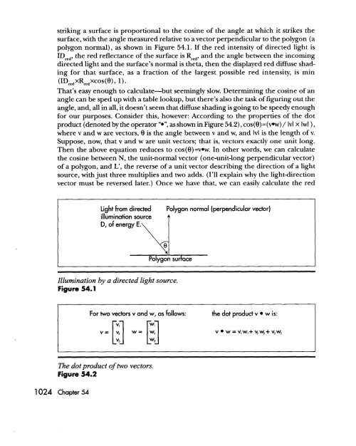
striking a surface is proportional to the cosine of the angle at which it strikes thesurface, with the angle measured relative to a vector perpendicular to the polygon (apolygon normal), as shown in Figure <strong>54</strong>.1. If the red intensity of directed light isIDred, the red reflectance of the surface is Rred, and the angle between the incomingdirected light and the surface’s normal is theta, then the displayed red diffuse shadingfor that surface, as a fraction of the largest possible red intensity, is min(1D,edxRre,xcos(8), ’)*That’s easy enough to calculate-but seemingly slow. Determining the cosine of anangle can be sped up with a table lookup, but there’s also the task of figuring out theangle, and, all in all, it doesn’t seem“.”,that diffuse shading is going to be speedy enoughfor our purposes. Consider this, however: According to the properties of the dotproduct (denoted by the operator as shown in Figure <strong>54</strong>.2), cos(B)=(vw) / IvI X IwI ),where v and w are vectors, 8 is the angle between v and w, and Ivl is the length of v.Suppose, now, that v and w are unit vectors; that is, vectors exactly one unit long.Then the above equation reduces to cos(e)=v.w. In other words, we can calculatethe cosine between N, the unit-normal vector (one-unit-long perpendicular vector)of a polygon, and L’, the reverse of a unit vector describing the direction of a lightsource, with just three multiplies and two adds. (I’ll explain why the lightdirectionvector must be reversed later.) Once we have that, we can easily calculate the redLight from directed Polygon normal (perpendicular vector)illumination sourceD, of energy E.Illumination by a directed light source.Figure <strong>54</strong>.1For two vectors v and w, as follows: the dot product vw is:vw = v,w,+ yw,+ v,w,The dot product of two vectors.Figure <strong>54</strong>.21024 <strong>Chapter</strong> <strong>54</strong>