User Manual - Arian S. A.
User Manual - Arian S. A.
User Manual - Arian S. A.
- No tags were found...

You also want an ePaper? Increase the reach of your titles
YUMPU automatically turns print PDFs into web optimized ePapers that Google loves.
PRELIMINARY INFORMATIONThis document haves copyright reserved, C <strong>Arian</strong> INC.Referred trademarks are of property of its respective owners.ARIAN is registered by <strong>Arian</strong> S.A.Technical helpIf you find problems with the instrument, check its configuration to becoherent with the application. If still it persists the problem, help canobtain by the following media:e-mail arian@arian.clphone/fax 56-2-4218333web www.arian.clRevision historyrev. 01/05rev. 2010-02First release.Magnetic pickup input is incorporated.
GENERAL DESCRIPTION ......................................................................... 4PART CODE .................................................................................................................... 5TECHNICAL SPECIFICATIONS ..................................................................................... 6INSTALLATION ........................................................................................... 7Alarm outputs .................................................................................................................. 8External reset inputs. ...................................................................................................... 8Analog outputs (optional) ............................................................................................... 8RS485 serial communications. (optional) ....................................................................... 8Power supply ................................................................................................................... 8Panel assembly ............................................................................................................... 8CONFIGURATION FROM PC (RPS) .......................................................... 9CONFIGURATION .................................................................................... 10General Configuration menu ( O P E r ). ....................................................................... 11Input configuration ........................................................................................................ 13Alarms configuration. .................................................................................................... 15Analog output configuration 4-20 mA. or 0-10V ............................................................ 17Serial RS485 communications configuration. ............................................................... 19OPERATION ............................................................................................. 20Special reset functions. ................................................................................................. 20Access to special functions and registers. .................................................................... 20Sub-menu r E A d , examine parameter values........................................................... 21Sub-menu F u n c , reset maximum, minimum, disabling outputs. ................................ 21Modify alarms Set Points. ............................................................................................. 22APPENDIX A ............................................................................................ 27How to enter a number in floating point format from frontal buttons . ........................... 27
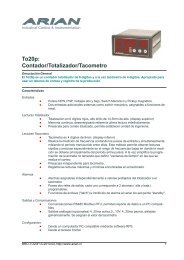
GENERAL DESCRIPTIONThe To20p is a 6 digit totalizer counter and 4 digit rate meter. Suitable forbeen used on counting and production control.Inputs- Pulses NPN, PNP, Mechanical switch, High and low Voltages.- Two additional external inputs (dry contact) programmable as reset functions.Counter display- 6 High bright 14.5mm height red digits totalizer. (upper display)- Continuous memory, stores last reading.- Counter pre-scale, adjust for any engineering unit.Rate meter display- Four 9mm digits. ( Lower display)- Pulses counting is done simultaneously measuring the time period betweensuccessive pulses. This method allows precise and quick readingsespecially at low frequencies where the measurement is obtained mainlyfrom the period among pulses. Also simplifies the input programming, nothaving to define “time windows” in which the count is carried out.- Separate rate meter pre-scale.- Registers maximum and minimum readings for the rate.Alarms- Pre set values can be assigned to the totalized count or the rate.- Two output relays, with two programmable alarms each ( high and low)- Latch and standby functions.Outputs and Communications- RS485 Modbus RTU serial communications reports data to a PC or PLC.- Galvanically isolated analog outputs for the rate meter,active loop 4..20ma ,0...10V, passive loop 4..20ma.Configuration.- From a PC compatible by means of RPS software.- From frontal push buttons.MANRUNOUT1OUT2<strong>User</strong> <strong>Manual</strong> to20p, rev.01/05, www.arian.cl4
PART CODEDefining a part number must be done selecting the following options.Last 2 ones (-420A, -420L), -RS85 are optional that must not be includedif no required.TO20P-AC-DC-420A-420L-RS485-AC :power supply 85...260 Vac, 6 W, 45...65 Hz.-DC :power supply 18....60 Vdc, 6 WOPTIONAL OUTPUT-420L :4..20ma passive loop-420A :4..20ma active, includes also 0..10VdcFor example:OPTIONAL-RS485 :modbus RTU serial communicationsTO20P-ACto20p counter, AC power supply , without any optional output.TO20P-DC-RS485to20p counter, DC power supply and modbus RTU serial communications.<strong>User</strong> <strong>Manual</strong> to20p, rev.01/05, www.arian.cl5
TECHNICAL SPECIFICATIONSINPUTSPulse inputs: NPN, PNP, Mechanical switch, TTL, High voltage (500 V) and magneticpickup (200mV AC min.)Provides feeding for input sensor, +5, -7.5 Vdc, 30mA max.Frequency range 0.01Hz ... 50KHzDISPLAYALARMS:OUTPUTS:Optional:Allows engineering units with decimal places for totalized count and rate display.Register max/min rate readings.Counter: 6 digits Display (14mm), range 0...999999Rate: 4 digits (9mm), range -999... 99992 independent alarm outputs, each one with high and/or low alarm, with absolute orrelative set points.Programmable alarm latch and "standby" that inhibits alarms when modifying setpoints).Can be assigned independently to the rate or counter.Relays, 2 outputs for alarms 250VAC/ 3A., normally open or normally close by software.-420L 4... 20 mA, loop powered, Vdrop 4.5V max. opto isolated (5kV).-420A 4..20ma/0-10V Active loop, opto isolated (5kV).-RS485 modbus RTU serial communications, opto isolated (5kV).POWER SUPPLY:Current mode switching power supply.Versions:85...260 Vac, 6 W, 45...65 Hz.20...60 VDC, 6 W, (optional)CONSTRUCTION:Aluminum and Polycarbonate; IP65Total Dimension:DIN 1/8; 96 x 48 x 135 mm.Panel cut:92 x 45 mm.Weight:300 grams.Operation temperature: 0 ... 50 °C.<strong>User</strong> <strong>Manual</strong> to20p, rev.01/05, www.arian.cl6
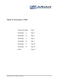
INSTALLATIONThe to20p ratemeter/counter admits 5 different input pulse types with amaximum frequency of 50khz and minimum of 0.01 Hz.There are some internal jumpers to be configured according to the inputtype (see picture in following page)Open collector input (terminals #11, #2, #1) used with inductive proximityswitchs or any device with NPN, PNP open collector output.Feeding the sensor is done by terminals #1 and #2 that supply +5v and -7.5v limited to 35mA max.High voltage input (terminals #10 , #3) for pulses on the range15V...500V. Can be AC pulse with cero cross.TTL and low voltages (terminals #11, #3) need pulses higher than 3Vand lower than 50V. Voltage must go down to 1V to be recognized.Magnetic pick up (terminals #11, #3) need a signal higher than 200mVAC.Mechanical switch (terminals #11, #2) used with relays or push-button.TO20PElectrical conectionsGnd (3)ANALOG OUT+S1 (11)V_Gnd ( 3)TTL and Magnetic Pick UpSignalHV S1ResetEx2 Ex1RS-485B AGnd +V-I +I+V_High VoltageHV (10)Gnd ( 3)+5 -7.5 Gnd 90..260VacSensor Supply P. SUPAlimentaciónOUT 1 OUT 2RELE RELES1 (11)-7.5V ( 2)Brown/CafeBlack/NegroBlue/Azul+5V ( 1)S1 (11)-7.5V ( 2)Mechanical SwitchInductive Switch NPN , PNP.FID2019B<strong>User</strong> <strong>Manual</strong> to20p, rev.01/05, www.arian.cl7
Configuración de PinesNPNPNPTTLSwitchMecanicoAlto Voltage200 mVMag. Pick Upfid20_15bAlarm outputsRelays are the standard option for alarm outputs. As seen in the figure,relay for alarm 1 (OUT 1) goes to terminals 6 and 7. The one for alarm 2(OUT 2) to terminals 8 and 9, both are normally open outputs (NO).Care must be taken on not exceeding the maximum relay current (3Amp.), since they would be damaged quickly. Is recommended to usefuses in series with the relays to protect them. Never use directly theinternal relay with the load. Always a external contactor should be used todrive the final load.External reset inputs.The instrument haves 2 external inputs for connecting push buttons orswitchs. In the configuration menu is assigned a function to the inputs,such reset total to cero, reset registered maximum and minimum.Switchs are connected to terminals #12, #13 and #3 (Gnd)Analog outputs (optional)For isolating and retransmitting the measured variable to a PLC or anotherinstrument. If this options are installed please refer to "analog outputconfiguration" chapter for details.RS485 serial communications. (optional)For communicating with PC or PLC using modbus RTU software protocol.This is an isolated out that drives standard RS485 5Volts signals. If thisoptions are installed please refer to "RS485 communications configuration"chapter for details.Power supplyThe instrument power supply is designed to operate with any voltagebetween 90 and 260 volts without need of adjustment. (20VDC to 60VDCfor the DC power supply option). Once start up will continue operatingunless the network fall under 50 VAC. The instrument possesses aninternal 0.5Amp fuse that should be replaced with a similar one.Panel assemblyDesigned for panel assembly in a 92 x 45 mm. cut (Format DIN 1/8).using clamps included with the instrument.<strong>User</strong> <strong>Manual</strong> to20p, rev.01/05, www.arian.cl8
CONFIGURATION FROM PC (RPS)Two displays versions may be programmed by frontal push bottoms whileone display versions does not have push bottoms, so only can be programmedfrom a PC compatible computer. The following is needed:- The PC compatible computer with vga monitor.- RPS software (download latest version from www.arian.cl)- Isolating interface cable. Part# RPS-CWhile using the RPS system the configurating menus are the same describedin following chapter for frontal push bottoms programming.With de-energized instrument, the interface cable must be connected byone side to the internal connector as shown in the picture.The other side of the cable goes to the PC serial RS232 port (DB9).Once done the connection the instrument must be energized and RPSsoftware executed in the PC.The interface cable does optical isolation between PC and instrument.Concluded the programming you must de-energized the device and thenplug off the interface cable.<strong>User</strong> <strong>Manual</strong> to20p, rev.01/05, www.arian.cl9
CONFIGURATIONOperation form must be programed on the configuration menu.IMPORTANT NOTE:Once entering on this menu the instrument stops counting input pulsesand will continue only when you exit the menu and returen to the operationmode.To enter the configuration menu press the center button [•] and withoutreleasing it, press and release one time the "right or upper" button [^] .Doing that, the message "KEY" will appear in the upper display. At thismoment the instrument asks for a access key. Now the number 2736should be introduced in the lower display using the "left or lowering" and"right or upper" button. Once the number 2736 is in the lower display,press the button [•] to enter.Now in the upper display appears the message M E n u. With the lateralbuttons select one of the 5 menus and to press center button [•] toenter. To quit, select the option "SALi" or wait 16 seconds without pressingany button.M E n uO P E r.I n P t.A L - 1A L - 2General menu, configuring displays, operation modes andother options.input configuration.alarm 1 configuration.alarm 2 configuration.4 - 20. analog output, 0...10V, 4...20mA (if it is available)r 4 8 5S A L irs485 serial communications.Returns to operation mode.Once entering one of the menus, if no button is press in 16 seconds, thedevices returns automatically to operation mode.At the end of each menu, always is asked if is desired to program thenew data and then to quit or continue configuring. These questions arepresented as:P r o gS A L iis asked if is desired to program or not the instrument with the introducedvalues. Selecting "No", values recently placed will be erased and originalvalues will not change.N o Do not program new values.S i Set in EEPROM new values.Select “Si” for quit (exit) the menu and “N o” for returning back to thestarting of the actual configuration menu.N o Continue in this menu.S i Quit or exit the menu.<strong>User</strong> <strong>Manual</strong> to20p, rev.01/05, www.arian.cl10
General Configuration menu ( O P E r ).d i s. bRefers to the lower display.o F Fr A t EM A C SM i n iDisabled Display.Rate.Maximum rate.Minimum rate.P.d i. bPlaces a fixed decimal point in the lower display to facilitate the viewingengineering units.- - - - Without decimal point.- - -. -- -. - --. - - -P.d i. APlaces a fixed decimal point in the 6 digit higher display to facilitate viewingengineering units.The options are the same described for "display b".E t r.1A function is assigned to the external reset input 1, associated to terminal#12.o F Fr S t . Nr S t . Ad i . A Lr S t . Cthere is no function assigned.Reset registered maximum and minimum of rate.Reset latched alarms.Disable/restore momentarily the alarm relay outputs.While disabled the alarms, the "RUN" led on frontpanel blinks quickly.Reset to cero totalized count.E t r.2A function is assigned to the external reset input 21, associated to terminal#13.Options are the same described for previous case.b o t . LSpecial function set for the Lowering button [v] on the front panel. (theleft one).Options are the same described for previous case.b o t . HSpecial function set for the "high" button [^] on the front panel (the rightone).Options are the same of the previous one.<strong>User</strong> <strong>Manual</strong> to20p, rev.01/05, www.arian.cl11
F u . L c = No, SiSpecial functions lock.It should be set "Si", to restrict operator access to "F u n c" specialfunctions menu (e.g.. reset maximum, minimum, alarms, etc.) as describedin operation chapter.P r o g = No, SiSet "Si" for programming new data. Otherwise data will be lost whenquitting this menu.S A L i = No, SiSet “Si” for quitting this menu. Otherwise return back to its starting point.<strong>User</strong> <strong>Manual</strong> to20p, rev.01/05, www.arian.cl12
Input configurationPreviously must been set the input configurating pins (NPN, PNP, mechanicalswitch,..) as described in the installation chapter.RatemeterThe ratemeter measures frequency measurement by counting input pulsesand simultaneously measuring the period elapsed among them.This method permits to obtain precise and quick readings specially for lowfrequencies where the measurement is obtained mainly from the periodamong pulses. At the same time simplifies input programming not havingto define "time windows" in which count is carried out.For input calibration is required to set the instrument with the desiredreading Lx corresponding to a Fx frequency in Hz input pulses. That istime constant to be multiplied to input frequency for obtaining the reading.The ratemeter constant krAt is calculated by.k.rAt = Lx / FxThe division result must be in floating point format. In Appendix A isdescribed how to introduce floating point number from the frontal pushbuttons. If you are using the RPS for configurating from a PC, then youdon't need to look appendix A.For example in certain machine is desired to measure the turns by minute(RPM) of an axe with 7 pulse by turn. Also you need the rate with 2decimals of resolution.If the axe is working at 1 RPM, then the reading considering the 2 decimalsresolution must be Lx= 100 . Later you will set the decimal point tolook as 1.00.At 1 RPM the sensor sends 7 pulses by minute thenLx = 100Fx = 7 / 1minute = 7 / (60seg) = 0.11666666 Hz.k.rAt = Lx / Fx = 100/0.11666666 = 857.1428571TotalizerThe totalizer haves an independent prescale. In the same form as therate a floating point constant will be multiplied to the accumulated numberof pulses to obtain the 6 digit reading.[Reading] = k.c n t * [totalized pulses]The constant is calculated as:k.c n t = [Desired Reading] / [number of pulses for desired Reading]<strong>User</strong> <strong>Manual</strong> to20p, rev.01/05, www.arian.cl13
Using the same example of the axe sending 7 pulse by turn, let say thatfor each turn are transported 25 Kg of a material to be totalized since thelast reset with 1 decimal resolution (100gr).For finding the constant suppose the axe makes only 1 turn, sending 7pulses. The reading must be 25.0 in this case.The decimal point is set apart in the general menu, so reading is 250.k.c n t = [Desired Reading] / [number of pulses for desired Reading]k.c n t = [ 250] / [ 7 ] = 35.71428571k. r A t = floating pointProportional constant between frequency input in Hz an the rate reading.F I L t = 1 ... 16Corresponds to a time constant for filtering the rate reading. Internallythe instrument carries out a first order low pass filter calculation with timeconstant "FILt". Can be set between 1 and 16 seconds.Better you should leave this value set to 1 second, increasing it only if itsrequired by having noisy readings.k. c n t = floating pointProportional constant between totalized reading and the totalized numberof pulses since last reset.P r o g = No, SiSet "Si" for programming new data. Otherwise data will be lost whenquitting this menu.S A L i = No, SiSet “Si” for quitting this menu. Otherwise return back to its starting point.<strong>User</strong> <strong>Manual</strong> to20p, rev.01/05, www.arian.cl14
Alarms configuration.The to20p possesses 2 independent alarms (alarm-1 and alarm-2) eachone associated to a output relay (relay-1 and relay-2)This alarms can be associated to the rate or to the totalized count readingsindependently.Each one of the alarms (alarm-1 and alarm-2) haves 2 Set Points, highand low. The alarm will activate when the input passes one of these limit.Once the alarm condition is set, the upper display will operate intermittentlyindicating that this condition exists.Both Set Points (high and low) for each alarm possess programmablehysteresis and can be defined as absolute value or relative (displacement)to a common Set Point.Now is described the configuration for alarm-1.Configuration of alarm-2 is similar.A L A r Selects the variable associated with alarm 1.r A t E rateC n t r totalized countDepending on the selected option the alarm operation form varies.Selecting C n t r disables Latch and Standby functions. Also will be notavailable the d o n F option for high and low alarms.When r A t E is selected, then the following parameters are required.H i g hHigh set point for alarm-1.The parameters menu generated for each alarm type are described in theoperation chapter.o F Fo n F hd o n FDisabled.On/off with hysteresis high alarm. The alarm activateswhen input is higher than a value programed in theparameters menu.Dual on/off type high alarm. The alarm activates when inputis higher than a value defined by general Set Point "SP. rE"plus a displacement programed in the parameters menu.L o uLow set point for alarm-1.o F Fo n F hd o n FDisabled.On/off with hysteresis high alarm. The alarm activateswhen input is lower than a value programed in theparameters menu.Dual on/off type high alarm. The alarm activates when inputis lower than a value defined by general Set Point "SP. rE"minus a displacement programed in the parameters menu.<strong>User</strong> <strong>Manual</strong> to20p, rev.01/05, www.arian.cl15
L t c hEnable Latch alarm.If enabled, the alarm condition output will be maintained although thecondition that generated it disappears.Operator must reset the latched alarm from the front panel.No disableSi. enableS t b YThe "standby" function inhibits alarm activation when the operator changesthe Set Point or the instrument is powered up.If alarm condition is given in that situation, the activation of the alarm-1 isinhibited until the condition that generates the alarm disappears.After the condition that generates the alarm disappears (e.g.. the ratereading arrived to the new set point) then the alarm is ready to be activatedby normal operation.No disableSi. enabler E L EIs specified if the relay-1 will work normally open or normally closed. Thisrelay is active when alarm-1 condition exists.d i r Relay works direct , normally open.i n v Works inverted or normally closed.P r o g = No, SiSet "Si" for programming new data. Otherwise data will be lost whenquitting this menu.S A L i = No, SiSet “Si” for quitting this menu. Otherwise return back to its starting point.<strong>User</strong> <strong>Manual</strong> to20p, rev.01/05, www.arian.cl16
Analog output configuration 4-20 mA. or 0-10VThis output is optional although the configuration menu is in all instruments,hardware (the optional output board) could not be installed.There are 2 analog output types, both optically isolated.Option -420LP, is 4-20ma loop Powered that requires a voltage source inseries with the loop. Its typical use is conditioning and isolating processvariable for other instruments as e.g.. PLC or DCS.Option -420AC, is 0-20mA, 4-20mA or 0-10V, active output. Its used tosend the selected variable to instruments whose input should be active(powered) such as 0-10v or a 4-20ma loop powered valve.Exists an internal jumper that must be placed depending on current orvoltage output (see figure in the following page)The questions in the menu vary slightly according to board type installed.Option -420LP4 - 20 o F F Disable output.o nenabled.Option -420ACt Y P E o F F Disabled.0 - 2 0 0 to 20 mA.4 - 2 0 4 to 20 mA.0 - 1 0 0 to 10 Volts.V A r bAsks by the variable that will be transmitted. See in the following pagethe table for the possible analog output variables.E. i n F = -999... 9999Introduce the value of the selected output variable for which the outputwill deliver 4 mA. (or 0 Volts). For example if output for input temperaturewas selected, when “E. i n F” = 0, the output will be 4 mA for zero degreestemperature. For lower temperatures the output will descendeddown to 3.5 mA. aprox.E. S u P = -999... 9999Introduce the value of selected output variable for which the output willdeliver 20 mA. (or 10volts). For the same example, place “E. S u P” =1000, then the output will be 20 mA when temperature is 1000. Forhigher temperatures the output will rise up to 20.5mA.C A L iThis refers to output board calibration, is reserved for manufacturer use.P r o g = No, SiSet “Si” for programming new data. Otherwise data will be lost whenquitting this menu.S A L i = No, SiSet “Si” for quitting this menu. Otherwise return back to its starting point.<strong>User</strong> <strong>Manual</strong> to20p, rev.01/05, www.arian.cl17
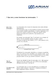
+-Option -420ACSalidas 4..20mA y 0..10V Activas4...20mA and 0...10Volts active output+RS-485B AANALOG OUTGnd +V-I +I4.5V min.+-PLCOpcion -420LPSalida 4..20mA pasiva alimentada por LazoLoop powerd 4...20mA output.Para la salida activa, opcion -420ACse debe colocar el PIN en una delas dos posiciones según sea lasalida de corriente o voltajeFor active output option -420AC,internal jumper must be set.4..20mA0...10V420OUT_00Possible analog output variables for the to20pr A t eRate reading. This is the only option.For example, setting:E. i n F = 0, The output is 4 mA for 0 rate reading.E. S u P = 1000The output is 20ma for rate 1000 reading. For higher reading outputsaturates in 20.5ma<strong>User</strong> <strong>Manual</strong> to20p, rev.01/05, www.arian.cl18
Serial RS485 communications configuration.Serial rs485 communications are optional, although the configuration menuis in all the instruments, hardware for its operation could not be installed.The command description for the communications protocol is available asfile in internet (www.arian.cl) and includes tag listing with its propertiesand scales.Characteristics : - RS485 physical protocol with optically isolated interface.- start bit, 8 data bits, parity bit = 0, stop bit- communication protocol, Modbus RTU ,functions 03, 06, 10The questions in the configuration menu are the following.n o d E o F F , oNEnable or disable communications.b A u d 300, 600, 1200, 2400, 3600, 4800, 9600, 19.2kCommunication speed.n. S c L = 1...247Slave number.P r o g = No, SiSet “Si” for programming new data. Otherwise data will be lost whenquitting this menu.S A L i = No, SiSet “Si” for quitting this menu. Otherwise return back to its starting point.<strong>User</strong> <strong>Manual</strong> to20p, rev.01/05, www.arian.cl19
OPERATIONThe location of the front panel buttons can be seen in the figure. Thecentral button [•] is the main one, is used for selecting and enteringparameters. Lateral buttons are used to increase or decrease selectedparameter.DISPLAY ADISPLAY BMANRUNOUT1OUT2Activated alarmLeds "OUT 1" and " OUT 2" reflect alarm relays state (activated ordesactivated) . Once an alarm (AL- or AL-2) is activated, the lower displayreading starts blinking (1 time/2 seconds) for advising the operator that aalarm condition has occurred.Special reset functions.If these functions are enabled from the general configuration menu, ispossible to reset the maximums, minimum, latched alarms or disablemomentarily the relay outputs by pressing one of the front panel buttons[^] or [v].Access to special functions and registers.For entering to the menu press the center button [•], immediately one of2 submenus should be selected by means of the lateral buttons andfinally press again the center button [•] to enter the selected sub-menu.r E A dF u n cExamine parameters values.Reset functions and outputs disable.While you are within this menus, the instruments continues counting inputpulses.Following the content of each sub-menu is described.<strong>User</strong> <strong>Manual</strong> to20p, rev.01/05, www.arian.cl20
Sub-menu r E A d , examine parameter values.This menu only permits to examine (not to modify) the values of someinternal parameters.With lateral buttons you can scan parameters. Pressing central buttonsreturns to normal operation mode.r A t EM A C SM i n iS P. r Erate reading.Maximum registered rate.Minimum registered rate.Shows general Set Point for alarms configured with relative set points.Sub-menu F u n c , reset maximum, minimum, disabling outputs.This menu can be locked from the configuration menu, in that case theupper display shows the message L o c k .Once entering this Sub-menu can be selected one of the following specialfunctions that will be executed immediately.r S t . Nr S t . Ad i . A Lr S t . CResets registered maximum and minimum of PV.Resets latched alarms.Disables momentarily and enables the relay outputs.If outputs are momentarily disabled by this function, the RUN led in frontpanel blinks rapidly.Resets ( returns to cero ) the totalized count.Once a function is selected with the lateral buttons press central button[•], and will be executed in the instantaneously and instrument returnsback to normal operation mode.If no button is press in 16 seconds, the instruments exits menu.<strong>User</strong> <strong>Manual</strong> to20p, rev.01/05, www.arian.cl21
Modify alarms Set Points.IMPORTANT NOTEOnce entering this menu the instrument stops counting input pulses andwill start counting again when you exit the menu.To enter the menu press the center button [•] and without releasing it,press and release one time the "right or upper" button [^] . Doing that, themessage "KEY" will appear in the upper display. At this moment theinstrument asks for a access key. Now the number 1234 should beintroduced in the lower display and then pressed the button [•] to enter.The to20p possesses 2 independent alarms (AL-1 and AL-2) each oneassociated to a output relay and can be linked to totalized count or rate.Each alarm possesses a high and low set points.When the measured variable is lower to the low set point or higher tohigh set point, the alarm and its corresponding relay is activated.For example the alarm-1, low has a set point SP.1L that can be obtainedin two different ways depending if it was configured as absolute (onFh) orrelative (donF) in the alarm configuration menu.SP.1L = S P. r E - 1. L . d S case donFSP.1L = 1. L . S Pcase onFhONAL-1, bajaOFFSP.1L - (1L.ht) /2SP.1L SP.1L + (1L.ht) /2In the same way for high alarm-1 :SP.1H = S P. r E + 1. H . d S case donFSP.1H = 1. H . S Pcase onFhONAL-1, altaOFFSP.1H - (1H.ht) /2SP.1H SP.1H + (1H.ht) /2This menu is diferent depending if you have chosen to associate thealarm to totalized count or rate also depends on the enabled options inthe configuration menu.<strong>User</strong> <strong>Manual</strong> to20p, rev.01/05, www.arian.cl22
Alarm-1, Rate associated.If alarm AL-1 or AL-2 or both are enabled as relative alarms, the is required to set:S P. r E = -999,... 9999General Set Point used in calculation of alarm operation point, only foralarms configured as relative ( d o n F ) .This parameter is asked only if some alarm was set as d o n F , othercase is omitted.Alarm-1, HighAccording on value H i g h for AL-1 configuration, the following cases will be given :Case o F FNothing is asked, high alarm is disabled.Case onFh1. H . SP = -999,... 9999Set Point for AL-1 high. Becomes active when:Rate > 1. H . SP Considering hysteresis.Case donF1. H . ht = 0... 999Hysteresis for the activation and desactivation of the AL-1 high.1. H . dS = -999,... 9999Alarm-1 high activation point separation referred to S P. r E .Will become active when:Rate > S P. r E + 1. H . d S Considering hysteresis.1. H . ht = 0... 999Hysteresis for the activation and desactivation of the AL-1 high.Alarm-1, LowAccording on value L o w for AL-1 configuration, the following cases will be given :Case o F FNothing is asked, low alarm is disabled.Case onFh1. L . SP = -999,... 9999Set Point for AL-1 low. Becomes active when:Rate < 1. L . SP Considering hysteresis.1. L . ht = 0... 999Hysteresis for the activation and desactivation of the AL-1 low.<strong>User</strong> <strong>Manual</strong> to20p, rev.01/05, www.arian.cl23
Case donF1. L . dS = -999,... 9999Alarm-1 low activation point separation referred to S P. r E .Will become active when:Rate < S P. r E - 1. L . d S Considering hysteresis.1. L . ht = 0... 999Hysteresis for the activation and desactivation of the AL-1 low.<strong>User</strong> <strong>Manual</strong> to20p, rev.01/05, www.arian.cl24
Alarm-2, Rate associated.Alarm-2, HighDepending on value of H i g h for AL-2 configuration, the following cases will be given:Case o F FNothing is asked, high alarm is disabled.Case onFh2. H . SP = -999,... 9999Set Point for AL-2 high. Becomes active when:Rate > 2. H . SP Considering hysteresis.Case donF2. H . ht = 0... 999Hysteresis for the activation and desactivation of the AL-2 high.2. H . dS = -999,... 9999Alarm-2 high activation point separation referred to S P. r E .Will become active when:Rate > S P. r E + 2. H . d S Considering hysteresis.2. H . ht = 0... 999Hysteresis for the activation and desactivation of the AL-2 high.Alarm-2, LowDepending on value of L o w for AL-2 configuration, the following cases will be given:Case o F FNothing is asked, low alarm is disabled.Case onFhCase donF2. L . SP = -999,... 9999Set Point for AL-2 low. Becomes active when:Rate < 2. L . SP Considering hysteresis.2. L . ht = 0... 999Hysteresis for the activation and desactivation of the AL-2 low.2. L . dS = -999,... 9999Alarm-2 low activation point separation refered to S P. r E .Will become active when:Rate < S P. r E - 2. L . d S Considering hysteresis.2. L . ht = 0... 999Hysteresis for the activation and desactivation of the AL-2 low.<strong>User</strong> <strong>Manual</strong> to20p, rev.01/05, www.arian.cl25
Alarm-1 associated to totalized count.Alarm-1, HighDepending on value of H i g h for AL-1 configuration, the following cases will be given:Case o F FCase onFhNothing is asked, high alarm is disabled.Set Point for AL-1 high is active when:Totalized count > SPSet point is entered in 2 parts, first the 4 less significant digits and thenthe 2 most significant in order to have a 6 digit number for SP.1.H.S.4 = 0,... 99991.H.S.4 = 0,... 99Alarm-1, LowDepending on value of L o w for AL-1 configuration, the following cases will be given:Case o F FCase onFhNothing is asked, low alarm is disabled.Set Point for AL-1 high is active when:Totalized count < SPSet point is entered in 2 parts, first the 4 less significant digits and thenthe 2 most significant in order to have a 6 digit number for SP.1.L.S.4 = 0,... 99991.L.S.4 = 0,... 99Alarm-2 associated to totalized count.Is configured in the same form as explained for Alarm-1, high and low.<strong>User</strong> <strong>Manual</strong> to20p, rev.01/05, www.arian.cl26
APPENDIX AHow to enter a number in floating point format from frontal buttons .First write the number in the following format:A. XXX YYY *10^ Ewhere,A one digit on the range -9 to + 9,XXX= B 3 digits on the range 000 to 999,YYY= C the 3 following digits also 000 to 999E this is the exponent on the range -38 to 38.Example, the number 1/701/70 = 0.014285714 = 1.4285714 *10^(-2) = 1. 428 571 4*10^ (-2)A = 1B = 428C = 571E = -2Another example, the number "pi" =3.141592, is put as:A = 3B = 141C = 592E = 0:Another example-80.023467*10^3-80.023467*10^3 = -8.0023467*10^4 = -8. 002 346 7*10^4A = -8B = 002C = 346E = 4The instrument will request for the 4 integer numbers A, B, C, EIn the "display b" will show always the name of the parameter that isentered, (e.g.. "k. rAt" )In "display A" are set the numbers A, B, C, E in order.The left digit will show the letter (A, b, C, E) indicating the integer to beentered. In the last 3 digits is set the number.Using the example for the number -8.0023467*10^4, the readings will be"A. -8""b 002""c 346""E. 4"<strong>User</strong> <strong>Manual</strong> to20p, rev.01/05, www.arian.cl27