ATSD20 Auxillary Transfer Switch Installation Instructions - Dual-Lite
ATSD20 Auxillary Transfer Switch Installation Instructions - Dual-Lite
ATSD20 Auxillary Transfer Switch Installation Instructions - Dual-Lite
- No tags were found...

Create successful ePaper yourself
Turn your PDF publications into a flip-book with our unique Google optimized e-Paper software.
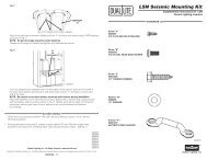
INSTALLATIONCAUTION: This unit has more than one power supply connection point.To reduce the risk of electric SHOCK, DISCONNECT ALL POWER SOURCESBEFORE INSTALLING OR SERVICING THIS UNIT.NOTE: SERVICE BY QUALIFIED PERSONNEL ONLY.NOTE: BEFORE INSTALLING THE RELAY CONTROL DEVICE, Make sure that the necessarybranch circuit wiring is available. An unswitched source of normal poweris required. A SEPARATE CONNECTION TO A CENTRAL INVERTER SYSTEM-SUPPLIED OR GENERATOR-SUPPLIED CIRCUIT MUST ALSO BE PROVIDED.1. FAMILIARIZE YOURSELF WITH THESE INSTRUCTIONS BEFORE BEGINNINGINSTALLATION.2. Mount the device in a convenient location using appropriate hardware (not supplied). SeeIllustration 1 for a typical installation.ILLUSTRATION 1Wall Mounting3. Disconnect AC power from all supply circuits.4. Remove device lid and install necessary conduit and wiring (not supplied) to the device (referto illustrations 3 to 8 following for proper wiring connections).4a. When using class 2 power limited circuits, remember to keep this wiring separate from highvoltage wiring by using separate conduit and the enclosure knockout supplied.5. Replace device lid and secure.INSTALLATIONILLUSTRATION 2ILLUSTRATION 3EMERGENCYCKT BKRPANELWire gaugesfor ALL leadsterminating atT2 should be#18 AWG.GTD20A RElayControl ELECTRONICS Device1 2 3 4 5 6 7electronics COVERcoverGTD20A device terminal TERMINAL blocks BLOCKST1*T2*1 2 3 4 5 6 7EMERGENCYCKT BKRPANELWire gaugesfor ALL leadsterminating atT2 should be#18 AWG.GTD20A RElayControl ELECTRONICS Deviceelectronics COVER coverGTD20A device terminal TERMINAL blocks BLOCKST1*T2*1 2 3 4 5 6 7 1 2 3 4 5 6 7HOTHOTNEUTRALLIGHTINGLOADUP TO20 ALOCALSWITCHINGMEANSHOTNORMALCKT BKRPANELNEUTRALLIGHTINGLOADUP TO20 ADIMMED HOTDIMMINGRACKHOTNORMALCKT BKRPANELNEUTRALNEUTRALNEUTRALDevice as an Inverter or Generator <strong>Transfer</strong> DeviceDevice as an Inverter or Generator <strong>Transfer</strong> Devicefor a Dimming Rack2
6. Mark each designated emergency lighting fixture with the red dot labels provided.7. Apply AC power to all circuits. The green "Normal Power Present" and the red "EmergencyPower Available" LED's should be illuminated.8. Perform a quick test as described on the unit label to check for proper operation. When thetest button is depressed, the green "Normal Power Present" LED should extinguish and thecontrolled lighting load should illuminate regardless of the local switch position providedemergency power is available (check red LED).9. During a quick test on a device installed with a dimming system, the fluorescent lighting loadshould illuminate at full lumen levels when the test switch is depressed regardless of thelumen level during normal operation.10. The entire central inverter or generator system, including all designated emergency loads,should be exercised to ensure proper operation (e.g., power up the emergency supply, throwthe transfer switch to the inverter or generator position, and check the emergency loads toverify they are operating properly from the emergency supply).OPERATIONThe device uses an internal relay contact to control the AC power feeding the lighting load. When thecentral inverter or generator supplies AC power to the lighting fixture, the device bypasses the local switchingmeans. This ensures the lighting load will be energized during central inverter or generator operationregardless of switch position.MAINTENANCENo routine maintenance is required to keep the device functional. However, it should be checked periodicallyto ensure that it is working properly. Note: Make sure to disconnect both the normal and emergency panelcircuit breakers before servicing.! REFER ANY SERVICING INDICATED BY THESE CHECKS TO QUALIFIED PERSONNEL !4