
You also want an ePaper? Increase the reach of your titles
YUMPU automatically turns print PDFs into web optimized ePapers that Google loves.
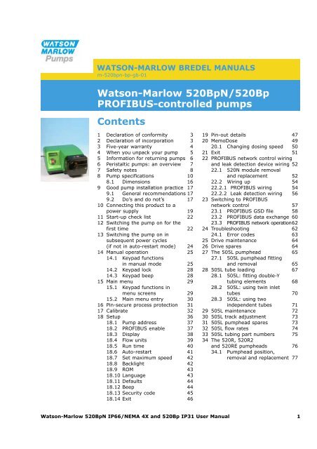
WATSON-MARLOW BREDEL MANUALS<br />
m-520bpn-bp-gb-01<br />
<strong>Watson</strong>-<strong>Marlow</strong> <strong>520BpN</strong>/520Bp<br />
PROFIBUS-controlled pumps<br />
Contents<br />
1 Declaration of conformity 3<br />
2 Declaration of incorporation 3<br />
3 Five-year warranty 4<br />
4 When you unpack your pump 5<br />
5 Information for returning pumps 6<br />
6 Peristaltic pumps: an overview 7<br />
7 Safety notes 8<br />
8 Pump specifications 10<br />
8.1 Dimensions 16<br />
9 Good pump installation practice 17<br />
9.1 General recommendations 17<br />
9.2 Do’s and do not’s 17<br />
10 Connecting this product to a<br />
power supply 19<br />
11 Start-up check list 22<br />
12 Switching the pump on for the<br />
first time 22<br />
13 Switching the pump on in<br />
subsequent power cycles<br />
(if not in auto-restart mode) 24<br />
14 Manual operation 25<br />
14.1 Keypad functions<br />
in manual mode 25<br />
14.2 Keypad lock 28<br />
14.3 Keypad beep 28<br />
15 Main menu 29<br />
15.1 Keypad functions in<br />
menu screens 29<br />
15.2 Main menu entry 30<br />
16 Pin-secure process protection 31<br />
17 Calibrate 32<br />
18 Setup 36<br />
18.1 Pump address 37<br />
18.2 PROFIBUS enable 37<br />
18.3 Display 38<br />
18.4 Flow units 39<br />
18.5 Run time 40<br />
18.6 Auto-restart 41<br />
18.7 Set maximum speed 42<br />
18.8 Backlight 42<br />
18.9 ROM 43<br />
18.10 Language 43<br />
18.11 Defaults 44<br />
18.12 Beep 44<br />
18.13 Security code 45<br />
18.14 Exit 46<br />
19 Pin-out details 47<br />
20 MemoDose 49<br />
20.1 Changing dosing speed 50<br />
21 Exit 51<br />
22 PROFIBUS network control wiring<br />
and leak detection device wiring 52<br />
22.1 520N module removal<br />
and replacement 52<br />
22.2 Wiring up 54<br />
22.2.1 PROFIBUS wiring 54<br />
22.2.2 Leak detection wiring 56<br />
23 Switching to PROFIBUS<br />
network control 57<br />
23.1 PROFIBUS GSD file 58<br />
23.2 PROFIBUS data exchange 60<br />
23.3 PROFIBUS network operation62<br />
24 Troubleshooting 62<br />
24.1 Error codes 63<br />
25 Drive maintenance 64<br />
26 Drive spares 64<br />
27 The 505L pumphead 65<br />
27.1 505L pumphead fitting<br />
and removal 65<br />
28 505L tube loading 67<br />
28.1 505L: fitting double-Y<br />
tubing elements 68<br />
28.2 505L: using twin inlet<br />
tubes 70<br />
28.3 505L: using two<br />
independent tubes 71<br />
29 505L maintenance 72<br />
30 505L track adjustment 73<br />
31 505L pumphead spares 73<br />
32 505L flow rates 74<br />
33 505L tubing part numbers 75<br />
34 The 520R, 520R2<br />
and 520RE pumpheads 76<br />
34.1 Pumphead position,<br />
removal and replacement 77<br />
<strong>Watson</strong>-<strong>Marlow</strong> <strong>520BpN</strong> IP66/NEMA 4X and 520Bp IP31 User Manual 1
35 520R, 520R2 and 520RE<br />
installation 79<br />
35.1 Opening the pumphead<br />
guard 79<br />
35.2 520R and 520R2<br />
tube loading 80<br />
35.3 520RE: fitting the<br />
drain port 81<br />
35.4 520RE element loading 82<br />
35.5 520RE element connection 84<br />
36 520R, 520R2 and 520RE<br />
maintenance 85<br />
37 520R, 520R2 and 520RE<br />
rotor settings 86<br />
38 520R, 520R2 and 520RE<br />
pumphead spares 87<br />
39 520R, 520R2 and 520RE<br />
flow rates 88<br />
40 520R, 520R2 and 520RE:<br />
tubing and element<br />
part numbers 96<br />
41 520 series pumping<br />
accessories 99<br />
42 Trademarks 100<br />
43 Patient-connected applications 100<br />
44 Publication history 100<br />
45 Decontamination certificate 101<br />
<strong>Watson</strong>-<strong>Marlow</strong> <strong>520BpN</strong> IP66/NEMA 4X and 520Bp IP31 User Manual 2
BpN, Bp<br />
BpN, Bp<br />
1 Declaration of conformity<br />
This declaration was issued for <strong>Watson</strong>-<strong>Marlow</strong> <strong>520BpN</strong> and 520Bp pumps<br />
on September 1, 2008. When this pump unit is used as a stand-alone<br />
pump it complies with: Machinery Directive 2006/42/EC, EMC Directive<br />
2004/108/EC.<br />
This pump is ETL listed: ETL control number 3050250. Cert to CAN/CSA<br />
std C22.2 No 61010-1. Conforms to UL std 61010A-1.<br />
See 8 Pump specifications.<br />
2 Declaration of incorporation<br />
When this pump unit is to be installed into a machine or is to be assembled with<br />
other machines for installations, it must not be put into service until the relevant<br />
machinery has been declared in conformity with the Machinery Directive<br />
2006/42/EC.<br />
Responsible person: Christopher Gadsden, Managing Director, <strong>Watson</strong>-<strong>Marlow</strong><br />
Limited, Falmouth, Cornwall TR11 4RU, England. Telephone +44 (0) 1326 370370<br />
Fax +44 (0) 1326 376009.<br />
The information in this user guide is believed to be correct at the time of publication.<br />
However, <strong>Watson</strong>-<strong>Marlow</strong> Limited accepts no liability for errors or omissions.<br />
<strong>Watson</strong>-<strong>Marlow</strong> Bredel has a policy of continuous product improvement, and<br />
reserves the right to alter specifications without notice. This manual is intended for<br />
use only with the pump it was issued with. Earlier or later models may differ. The<br />
most up-to-date manuals appear on the <strong>Watson</strong>-<strong>Marlow</strong> website:<br />
http://www.watson-marlow.com<br />
<strong>Watson</strong>-<strong>Marlow</strong> <strong>520BpN</strong> IP66/NEMA 4X and 520Bp IP31 User Manual 3
BpN, Bp<br />
3 Five year warranty<br />
520 cased pumps, 620 cased pumps and 720 cased pumps<br />
For any 520, 620 or 720 cased pump purchased after 1 January 2007, <strong>Watson</strong>-<br />
<strong>Marlow</strong> Limited (“<strong>Watson</strong>-<strong>Marlow</strong>”) warrants, subject to the conditions and exceptions<br />
below, through either <strong>Watson</strong>-<strong>Marlow</strong>, its subsidiaries, or its authorised distributors,<br />
to repair or replace free of charge, any part of the product which fails within<br />
five years of the day of manufacture of the product. Such failure must have occurred<br />
because of defect in material or workmanship and not as a result of operation of the<br />
product other than in normal operation as defined in this pump manual.<br />
<strong>Watson</strong>-<strong>Marlow</strong> shall not be liable for any loss, damage, or expense directly or indirectly<br />
related to or arising out of the use of its products, including damage or injury<br />
caused to other products, machinery, buildings, or property, and <strong>Watson</strong>-<strong>Marlow</strong><br />
shall not be liable for consequential damages, including, without limitation, lost profits,<br />
loss of time, inconvenience, loss of product being pumped, and loss of production.<br />
This warranty does not obligate <strong>Watson</strong>-<strong>Marlow</strong> to bear any costs of removal,<br />
installation, transportation, or other charges which may arise in connection with a<br />
warranty claim.<br />
Conditions of and specific exceptions to the above warranty are:<br />
Conditions<br />
� Products must be returned by pre-arrangement, carriage-paid, to <strong>Watson</strong>-<br />
<strong>Marlow</strong>, or a <strong>Watson</strong>-<strong>Marlow</strong> approved service centre.<br />
� All repairs or modifications must have been made by <strong>Watson</strong>-<strong>Marlow</strong> Limited,<br />
or a <strong>Watson</strong>-<strong>Marlow</strong> approved service centre or with the express permission of<br />
<strong>Watson</strong>-<strong>Marlow</strong>.<br />
� Warranties purporting to be on behalf of <strong>Watson</strong>-<strong>Marlow</strong> made by any person,<br />
including representatives of <strong>Watson</strong>-<strong>Marlow</strong>, its subsidiaries, or its distributors,<br />
which do not accord with the terms of this warranty shall not be binding upon<br />
<strong>Watson</strong>-<strong>Marlow</strong> unless expressly approved in writing by a Director or Manager<br />
of <strong>Watson</strong>-<strong>Marlow</strong>.<br />
Exceptions<br />
� The warranty shall not apply to repairs or service necessitated by normal wear<br />
and tear or for lack of reasonable and proper maintenance.<br />
� All tubing and pumping elements as consumable items are excluded.<br />
� Products which, in the judgment of <strong>Watson</strong>-<strong>Marlow</strong>, have been abused, misused,<br />
or subjected to malicious or accidental damage or neglect are excluded.<br />
� Electrical surge as a cause of failure is excluded.<br />
� Chemical attack is excluded<br />
� All pumphead rollers are excluded.<br />
� The 620R family of pumpheads are excluded from all warranty when pumping<br />
above 2 bar while above 165rpm.<br />
� Pumpheads from the 313/314 and the Microcassette ranges and any 701<br />
extension pumpheads are excluded and retain their one-year standard pumphead<br />
warranty. The drive they are attached to is subject to the five-year warranty<br />
as set out here.<br />
� Ancillaries such as leak detectors are excluded.<br />
<strong>Watson</strong>-<strong>Marlow</strong> <strong>520BpN</strong> IP66/NEMA 4X and 520Bp IP31 User Manual 4
BpN, Bp<br />
BpN<br />
Bp<br />
4 When you unpack your pump<br />
Unpack all parts carefully, retaining the packaging until you are sure all components<br />
are present and in good order. Check against the components supplied lists, below.<br />
Packaging disposal<br />
Dispose of packaging materials safely, and in accordance with regulations in your<br />
area. Pay particular attention to the expanded polystyrene shockproof shells. The<br />
outer carton is made of corrugated cardboard and can be recycled.<br />
Inspection<br />
Check that all components are present. Inspect components for damage in transit.<br />
If anything is missing or damaged, contact your distributor immediately.<br />
Components supplied (<strong>520BpN</strong> pump, IP66 NEMA 4X models)<br />
� The <strong>520BpN</strong> pump drive unit fitted with:<br />
� 520R2 or other pumphead (See 8 Pump specifications) if specified as a<br />
pump<br />
� A 520N module providing pump ingress protection to IP66, NEMA 4X.<br />
Note: the module is attached for transit, but must be removed to allow<br />
wiring up, voltage selection and fuse inspection and then re-affixed before<br />
the pump is operated.<br />
� The designated mains power lead for your pump<br />
� PC-readable CDROM containing these operating instructions<br />
� Quick Start manual<br />
Components supplied (520Bp pump, IP31 models)<br />
� The 520Bp pump drive unit fitted with:<br />
� 520R2 or other pumphead (See 8 Pump specifications) if specified as a<br />
pump<br />
� The designated mains power lead for your pump<br />
� PC-readable CDROM containing these operating instructions<br />
� Quick Start manual<br />
Note: Some versions of this product will include components different from those<br />
listed above. Check against your purchase order.<br />
<strong>Watson</strong>-<strong>Marlow</strong> <strong>520BpN</strong> IP66/NEMA 4X and 520Bp IP31 User Manual 5
BpN, Bp<br />
BpN, Bp<br />
Storage<br />
This product has an extended shelf life. However, care should be taken after storage<br />
to ensure that all parts function correctly. Users should be aware that the pump contains<br />
a battery with an unused life of seven years. Long-term storage is not recommended<br />
for peristaltic pump tubing. Please observe the storage recommendations<br />
and use-by dates which apply to tubing you may wish to bring into service after storage.<br />
5 Information for returning pumps<br />
Equipment which has been contaminated with, or exposed to, body fluids, toxic<br />
chemicals or any other substance hazardous to health must be decontaminated<br />
before it is returned to <strong>Watson</strong>-<strong>Marlow</strong> or its distributor.<br />
A certificate included at the rear of these operating instructions, or signed statement,<br />
must be attached to the outside of the shipping carton. This certificate is<br />
required even if the pump is unused. See 45 Decontamination certificate.<br />
If the pump has been used, the fluids that have been in contact with the pump and<br />
the cleaning procedure must be specified along with a statement that the equipment<br />
has been decontaminated.<br />
<strong>Watson</strong>-<strong>Marlow</strong> <strong>520BpN</strong> IP66/NEMA 4X and 520Bp IP31 User Manual 6
BpN, Bp<br />
6 Peristaltic pumps - an overview<br />
Peristaltic pumps are the simplest possible pump, with no valves, seals or glands to<br />
clog or corrode. The fluid contacts only the bore of a tube, eliminating the risk of the<br />
pump contaminating the fluid, or the fluid contaminating the pump. Peristaltic<br />
pumps can operate dry without risk.<br />
How they work<br />
A compressible tube is squeezed between a roller and a track on an arc of a circle,<br />
creating a seal at the point of contact. As the roller advances along the tube, the<br />
seal also advances. After the roller has passed, the tube returns to its original shape,<br />
creating a partial vacuum which is filled by fluid drawn from the inlet port.<br />
Before the roller reaches the end of the track, a second roller compresses the tube<br />
at the start of the track, isolating a packet of fluid between the compression points.<br />
As the first roller leaves the track, the second continues to advance, expelling the<br />
packet of fluid through the pump’s discharge port. At the same time, a new partial<br />
vacuum is created behind the second roller into which more fluid is drawn from the<br />
inlet port.<br />
Backflow and siphoning do not occur, and the pump effectively seals the tube when<br />
it is inactive. No valves are needed.<br />
The principle may be demonstrated by squeezing a soft tube between thumb and<br />
finger and sliding it along: fluid is expelled from one end of the tube while more is<br />
drawn in at the other.<br />
Animal digestive tracts function in a similar way.<br />
Suitable applications<br />
Peristaltic pumping is ideal for most fluids, including viscous, shear-sensitive, corrosive<br />
and abrasive fluids, and those containing suspended solids. They are especially<br />
useful for pumping operations where hygiene is important.<br />
Peristaltic pumps operate on the positive displacement principle. They are particularly<br />
suitable for metering, dosing and dispensing applications. Pumps are easy to<br />
install, simple to operate and inexpensive to maintain.<br />
<strong>Watson</strong>-<strong>Marlow</strong> <strong>520BpN</strong> IP66/NEMA 4X and 520Bp IP31 User Manual 7
7 Safety notes<br />
In the interests of safety, this pump and the tubing selected should only be used by<br />
competent, suitably trained personnel after they have read and understood this<br />
manual, and considered any hazard involved. If the pump is used in a manner not<br />
specified by <strong>Watson</strong>-<strong>Marlow</strong> Ltd, the protection provided by the pump may be<br />
impaired.<br />
Any person who is involved in the installation or maintenance of this equipment<br />
should be fully competent to carry out the work. In the UK this person should also<br />
be familiar with the Health and Safety at Work Act 1974.<br />
This symbol, used on the pump and in this manual,<br />
means: Caution, refer to accompanying documents.<br />
This symbol, used on the pump and in this manual,<br />
means: Do not allow fingers to contact moving parts.<br />
This symbol, used on the pump and in this manual,<br />
means: Recycle this product under the terms of the EU<br />
Waste Electrical and Electronic Equipment (WEEE)<br />
Directive.<br />
Fundamental work with regard to lifting, transportation,<br />
installation, starting-up, maintenance<br />
and repair should be perfor med by qualified personnel<br />
only. The unit must be isolated from mains power<br />
while work is being carried out. The motor must be secured<br />
against accidental start-up.<br />
There is a user-replaceable type T2,5A H 250V<br />
fuse in the fuseholder in the centre of the switchplate<br />
at the back of the pump. In some countries,<br />
the mains power plug contains an additional replaceable fuse.<br />
There is a fuse on the interface card which self-resets after<br />
five seconds. There are no user-serviceable fuses or parts<br />
inside this pump.<br />
<strong>Watson</strong>-<strong>Marlow</strong> <strong>520BpN</strong> IP66/NEMA 4X and 520Bp IP31 User Manual 8
There are moving parts inside the pumphead. Before opening the toolunlockable<br />
pumphead guard, ensure that the following safety directions are<br />
followed.<br />
� Ensure that the pump is isolated from the mains power.<br />
� Ensure that there is no pressure in the pipeline.<br />
� If a tube failure has occurred, ensure that any fluid in the pumphead has been<br />
allowed to drain to a suitable vessel, container or drain.<br />
� Ensure that protective clothing and eye protection are worn if hazardous fluids<br />
are pumped.<br />
� Primary operator protection from rotating parts of the pump is provided by the<br />
pumphead safeguard. Note that safeguards differ, depending on the type of<br />
pumphead. See the Pumpheads sections of this manual: 27 and 34.<br />
This pump must be used only for its intended purpose.<br />
The pump must be accessible at all times to facilitate operation and maintenance.<br />
Access points must not be obstructed or blocked. Do not fit any devices to the drive<br />
unit other than those tested and approved by <strong>Watson</strong>-<strong>Marlow</strong>. Doing so could lead<br />
to injury to persons or damage to property for which no liability can be accepted.<br />
If hazardous fluids are to be pumped, safety procedures specific to the particular<br />
fluid and application must be put in place to protect against injury to persons.<br />
The exterior surfaces of the pump may get hot during operation. Do not take hold<br />
of the pump while it is running. Let it cool after use before handling it. The drive unit<br />
must not be run without a pumphead fitted.<br />
This product does not comply with the ATEX directive and<br />
must not be used in explosive atmospheres.<br />
<strong>Watson</strong>-<strong>Marlow</strong> <strong>520BpN</strong> IP66/NEMA 4X and 520Bp IP31 User Manual 9
BpN<br />
BpN, Bp<br />
8 Pump specifications<br />
Labels fixed to the rear of the pump contain manufacturer and contact details, product<br />
reference number, serial number and model details.<br />
The same information is carried on the drive’s backplate, accessible when the 520N<br />
module is removed.<br />
<strong>Watson</strong>-<strong>Marlow</strong> <strong>520BpN</strong> IP66/NEMA 4X and 520Bp IP31 User Manual 10
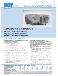
<strong>520BpN</strong>, IP66 NEMA 4X model and 520Bp, IP31 model<br />
This pump can be controlled from the keypad or remotely. It features:<br />
Manual control<br />
Speed adjustment; run and stop; direction control; keypad scaling; “max” key<br />
for rapid priming.<br />
PROFIBUS control<br />
Remote control via PROFIBUS DP V0. See PROFIBUS digital communications,<br />
below.<br />
MemoDose<br />
Allows precise repeat dosing. Stores in memory a pulse count from the motor.<br />
This count is repeated each time START is pressed to provide a single-shot<br />
dose.<br />
Calibration<br />
Full calibration with default figures for a range of pumpheads and tubes.<br />
Calibration dose facility.<br />
<strong>Watson</strong>-<strong>Marlow</strong> <strong>520BpN</strong> IP66/NEMA 4X and 520Bp IP31 User Manual 11
PROFIBUS digital communications<br />
PROFIBUS is a system of digital communications widely used in process<br />
automation. A central programmable controller—the PROFIBUS master—controls<br />
up to 125 devices such as pumps, valves and instruments—slaves.<br />
The master can send information to the pump, such as an instruction to start<br />
or stop; and interrogate the pump about its condition: whether it is running, for<br />
example, or whether it has a fault. Communication is via a dedicated, shielded,<br />
two-core cable which connects devices serially to the master.<br />
PROFIBUS/<strong>520BpN</strong>/520Bp capability<br />
Configuration:<br />
� Set pump address (see 18 Setup) � PROFIBUS enable (see 18 Setup)<br />
Parameters:<br />
� Minimum speed (not 520Bp)<br />
� Maximum speed<br />
� Pump model<br />
Data flow, master to pump:<br />
� Set speed<br />
� Rotation direction<br />
� Start / stop<br />
� Flow calibration<br />
Diagnostics:<br />
� General fault flag<br />
� Pump software version<br />
� PROFIBUS software version<br />
� Leak detection device<br />
Extended diagnostics:<br />
� Over current<br />
� Over voltage<br />
� Under voltage<br />
� Over temperature<br />
� Pumphead<br />
� Tubing bore size<br />
Data flow, pump to master:<br />
� Measured speed<br />
� Running hours<br />
� Tacho count<br />
� Flow calibration<br />
� Upper speed limit exceeded<br />
� Lower speed limit exceeded (not<br />
520Bp)<br />
� Stalled<br />
� Tacho fault<br />
� Out of range details<br />
For more information on this pump and PROFIBUS, see 22.2.1 PROFIBUS<br />
wiring and 23 Switching to PROFIBUS network control. Refer to PROFIBUS<br />
International for PROFIBUS control information. This product uses a version<br />
of PROFIBUS called PROFIBUS Decentralised Periphery V0, and adheres to<br />
the International Standard and device certification by PROFIBUS<br />
International: http://www.profibus.com.<br />
<strong>Watson</strong>-<strong>Marlow</strong> <strong>520BpN</strong> IP66/NEMA 4X and 520Bp IP31 User Manual 12
IP (Ingress Protection) and NEMA definitions<br />
3<br />
5<br />
6<br />
IP NEMA<br />
1st Digit 2nd Digit<br />
Protected against<br />
ingress of solid objects<br />
with a diameter of<br />
more than 2.5mm.<br />
Tools, wires etc with a<br />
thickness of more than<br />
2.5mm are prevented<br />
from approach<br />
Protected against<br />
harmful dust deposits.<br />
Ingress of dust is not<br />
totally prevented but<br />
the dust must not<br />
enter in sufficient<br />
quantity to interfere<br />
with satisfactory<br />
operation of the<br />
equipment. Complete<br />
protection against<br />
contact<br />
Protection against<br />
ingress of dust (dusttight).<br />
Complete<br />
protection against<br />
contact<br />
1<br />
5<br />
6<br />
Protection against<br />
dripping water falling<br />
vertically. No harmful<br />
effect must be<br />
produced<br />
Protection against<br />
water projected from a<br />
nozzle against the<br />
equipment (enclosure)<br />
from any direction.<br />
There must be no<br />
harmful effect (water<br />
jet)<br />
Protection against<br />
heavy seas or powerful<br />
water jets. Water must<br />
not enter the<br />
equipment (enclosure)<br />
in harmful quantities<br />
(splashing over)<br />
* 520N cased pumps are rated to NEMA 4X (indoor use) only.<br />
<strong>Watson</strong>-<strong>Marlow</strong> <strong>520BpN</strong> IP66/NEMA 4X and 520Bp IP31 User Manual 13<br />
2<br />
12<br />
13<br />
4X<br />
Indoor use to provide a<br />
degree of protection<br />
against limited amounts<br />
of falling water and dirt<br />
Indoor use to provide a<br />
degree of protection<br />
against dust, falling dirt<br />
and dripping, noncorrosive<br />
liquids<br />
Indoor use to provide a<br />
degree of protection<br />
against dust and<br />
spraying water, oil and<br />
non-corrosive coolants<br />
Indoor or outdoor* use<br />
to provide a degree of<br />
protection against<br />
splashing water, windblown<br />
dust and rain,<br />
hose-directed water;<br />
undamaged by the<br />
formation of ice on the<br />
enclosure. (Resist<br />
corrosion: 200-hour salt<br />
spray)
Pump specifications<br />
Control range (turndown ratio) 0.1-220rpm (2,200:1)<br />
Supply voltage/frequency 100-120V/200-240V 50/60Hz 1ph<br />
±10% of nominal voltage.<br />
Maximum voltage fluctuation<br />
A well regulated electrical mains supply<br />
is required along with cable connections<br />
to the best practice of noise immunity<br />
Installation category<br />
(overvoltage category)<br />
II<br />
Power consumption 135VA<br />
Full load current
Standards<br />
EC<br />
harmonised<br />
standards<br />
Other<br />
standards<br />
Safety of machinery—electrical equipment of machines:<br />
BS EN 60204-1<br />
Safety requirements for electrical equipment for measurement,<br />
control and laboratory use:<br />
BS EN 61010-1 incorporating A2 Category 2, Pollution degree 2<br />
Degrees of protection provided by enclosures (IP code):<br />
BS EN 60529 amendments 1 and 2<br />
Conducted emissions:<br />
BS EN 55011 A1 and A2 Class A, called by BS EN61000-6-4<br />
Radiated emissions:<br />
BS EN 55011 A1 and A2 Class A, called by BS EN61000-6-4<br />
Electrostatic discharge: BS EN 61000-4-2<br />
Radiated RF immunity:<br />
BS EN 61000-4-3 A1 and A2, called by BS EN 61000-6-2<br />
Fast transient burst:<br />
BS EN 61000-4-4 A1 and A2, Level 3 (2kV),<br />
called by BS EN 61000-6-2<br />
Surge immunity:<br />
BS EN 61000-4-5 A1 and A2, called by BS EN 61000-6-2<br />
Conducted RF immunity:<br />
BS EN 61000-4-6, called by BS EN 61000-6-2<br />
Voltage dips and interruptions:<br />
BS EN 61000-4-11, called by BS EN 61000-6-2<br />
Mains harmonics: BS EN 61000-3-2 A2<br />
Pumps and pump units for liquids—common safety<br />
requirements: BS EN 809<br />
UL 61010A-1<br />
CAN/CSA-C22.2 No 61010-1<br />
Conducted emissions FCC 47CFR, Part 15.107<br />
Radiated emissions FCC 47CFR, Part 15<br />
NEMA 4X to NEMA 250 (indoor use) for IP66 products only<br />
PROFIBUS Certificate<br />
<strong>Watson</strong>-<strong>Marlow</strong> <strong>520BpN</strong> IP66/NEMA 4X and 520Bp IP31 User Manual 15
8.1 Dimensions<br />
<strong>520BpN</strong> IP66/NEMA 4X model and 520Bp IP31 models;<br />
520R pumphead<br />
<strong>520BpN</strong> IP66/NEMA 4X model and 520Bp IP31 models;<br />
505L pumphead<br />
Note: <strong>520BpN</strong> and 520Bp pumps are the same size except that the 520Bp lacks the<br />
520N module at the rear of the pump.<br />
Unit weights<br />
<strong>520BpN</strong>:<br />
IP66, NEMA 4X<br />
520Bp: IP31<br />
Drive only + 520R, 520R2<br />
10.58kg<br />
23lb 5oz<br />
9.70kg<br />
21lb 6oz<br />
11.48kg<br />
25lb 5oz<br />
10.60kg<br />
23lb 5oz<br />
+ 520<strong>REL</strong>,<br />
520REM, 520REH<br />
11.40kg<br />
25lb 2oz<br />
10.52kg<br />
23lb 3oz<br />
+ 505L<br />
13.06kg<br />
28lb 13oz<br />
12.18kg<br />
26lb 14oz<br />
<strong>Watson</strong>-<strong>Marlow</strong> <strong>520BpN</strong> IP66/NEMA 4X and 520Bp IP31 User Manual 16
BpN, Bp<br />
9 Good pump installation practice<br />
9.1 General recommendations<br />
A correctly engineered installation will promote long tube life. Site the pump on a<br />
flat, horizontal, rigid surface, free from excessive vibration, to ensure correct lubrication<br />
of the gearbox. Allow a free flow of air around the pump to ensure that heat<br />
can be dissipated. Ensure that the ambient temperature around the pump does not<br />
exceed 40C.<br />
The STOP key on the keypad will always stop the pump. However, it is recommended<br />
that a suitable local emergency stop device is fitted into the mains supply to the<br />
pump.<br />
Do not stack pumps more than three high. When pumps are stacked, ensure that<br />
the ambient temperature around all the pumps in the stack does not exceed 40C.<br />
The pump may be set up so that the direction of rotor rotation is clockwise or counter-clockwise,<br />
whichever is convenient. Please note, however, that for the 520R and<br />
501RL pumpheads tube life will be greater if the rotor rotates clockwise; and that<br />
performance against pressure will be maximised if the rotor rotates counter-clockwise.<br />
To achieve 4 bar and 7 bar pressures using a 520RE pump and the appropriate<br />
rotor and element, the pump must rotate counter-clockwise.<br />
Peristaltic pumps are self-priming and self-sealing against backflow. No valves are<br />
required in inlet or discharge lines, except as described below. Valves in the process<br />
flow must be opened before the pump operates. Users are advised to fit a pressure<br />
relief device between the pump and any valve on the discharge side of the pump to<br />
protect against damage caused by accidental operation with the discharge valve<br />
closed. Users of 520RE pumps at pressures up to 4 bar and 7 bar are advised to fit<br />
a non-return valve between the pump and the discharge pipework to avoid the sudden<br />
release of pressurised fluid in the unlikely event of element failure.<br />
9.2 Do’s and do not’s<br />
Do not build a pump into a tight location without adequate airflow around the pump.<br />
Do ensure that when the 520N watertight module is fitted the seals are intact and<br />
properly located.<br />
Do ensure that the holes for cable glands are properly sealed to maintain the IP66<br />
/ NEMA 4X rating.<br />
<strong>Watson</strong>-<strong>Marlow</strong> <strong>520BpN</strong> IP66/NEMA 4X and 520Bp IP31 User Manual 17
Do not strap the control and mains power cables together.<br />
Do avoid tight bends in PROFIBUS signal cable.<br />
Do keep delivery and suction tubes as short and direct as possible - though ideally<br />
not shorter than 1m - and follow the straightest route. Use bends of large radius: at<br />
least four times the tubing diameter. Ensure that connecting pipework and fittings<br />
are suitably rated to handle the predicted pipeline pressure. Avoid pipe reducers and<br />
lengths of smaller bore tubing than the pumphead section, particularly in pipelines<br />
on the suction side. Any valves in the pipeline (not usually needed with a self-priming<br />
peristaltic pump) must not restrict the flow. Any valves in the flow line must be<br />
open when the pump is running.<br />
Do use suction and delivery pipes equal to or larger than the bore of the tube in the<br />
pumphead. When pumping viscous fluids use pipe runs with a bore several times<br />
larger than the pump tube.<br />
Do ensure that on longer tube runs at least 1m of smooth bore flexible tubing is connected<br />
to the inlet and discharge port of the pumphead to help to minimise impulse<br />
losses and pulsation in the pipeline. This is especially important with viscous fluids<br />
and when connecting to rigid pipework.<br />
Do site the pump at or just below the level of the fluid to be pumped if possible.<br />
This will ensure flooded suction and maximum pumping efficiency.<br />
Do keep the pumphead track and all moving parts clean and free from contamination<br />
and debris.<br />
Do run at slow speed when pumping viscous fluids. When using the 520R pumphead,<br />
a 6.4mm or 4.8mm bore tube with a 2.4mm wall will give best results. Tube smaller<br />
than this will generate a high friction loss, so reducing the flow. Tube with a larger<br />
bore may not have sufficient strength to restitute fully. Flooded suction will enhance<br />
pumping performance in all cases, particularly for materials of a viscous nature.<br />
Do recalibrate after changing pump tubes, fluid, or any connecting pipework. It is<br />
also recommended that the pump is recalibrated periodically to maintain accuracy.<br />
IP66 / NEMA 4X models may be hosed down, but should not be immersed. Protect<br />
from prolonged UV exposure.<br />
When using Marprene or Bioprene continuous tubing, do re-tension the tube<br />
after the first 30 minutes of running.<br />
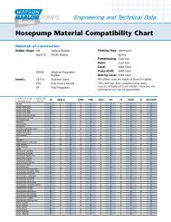
Tube selection: The chemical compatibility lists published in <strong>Watson</strong>-<strong>Marlow</strong> publications<br />
are guides. If in doubt about the compatibility of a tube material and the<br />
duty fluid, request a <strong>Watson</strong>-<strong>Marlow</strong> tube sample card for immersion trials.<br />
<strong>Watson</strong>-<strong>Marlow</strong> <strong>520BpN</strong> IP66/NEMA 4X and 520Bp IP31 User Manual 18
BpN, Bp<br />
BpN<br />
BpN, Bp<br />
BpN<br />
10 Connecting this product<br />
to a power supply<br />
The voltage selector is mounted in the switchplate at<br />
the rear of the pump, protected from water by the<br />
520N module. The module must be removed to allow<br />
access to the switchplate. See 22.1 520N module<br />
removal and replacement. Set the voltage selector<br />
to 115V for 100-120V 50/60Hz supplies or 230V for<br />
200-240V 50/60Hz supplies. Always check the voltage<br />
selector switch before connecting the mains supply.<br />
Make suitable connection to an earthed single-phase<br />
mains electricity supply.<br />
The voltage selector switch is not visible while the 520N<br />
module is in place. Do not switch the pump on unless<br />
you have checked that it is set to suit your power supply<br />
by removing the module and inspecting the switch,<br />
and then refitting the module. See 22.1 520N module removal<br />
and replacement.<br />
We recommend using commercially available supply<br />
voltage surge suppression where there is excessive<br />
electrical noise.<br />
Power cable: The pump is supplied fitted<br />
with a cable gland and approximately<br />
2.8m of power cable. Recommended<br />
cable: H05RN-F3G0.75; SJTW 105C 3-<br />
18AWG; max OD 8mm (5/16in).<br />
This drawing shows the cable connections<br />
from below with the interface card cover<br />
removed.<br />
Power cables of NEMA 4X specification<br />
pumps are fitted with a standard US<br />
mains power plug. IP66 specification<br />
pumps are supplied with no plug. The<br />
colour code for the power cable is: brown<br />
- live; blue - neutral; green and yellow -<br />
earth.<br />
<strong>Watson</strong>-<strong>Marlow</strong> <strong>520BpN</strong> IP66/NEMA 4X and 520Bp IP31 User Manual 19
BpN, Bp<br />
If the mains power cable is inappropriate for your installation, it can be changed.<br />
This operation can be carried out with the 520N module in place, or after it has been<br />
removed, as shown here for clarity.<br />
� Ensure that the pump is isolated from the mains power.<br />
� Remove the six screws from the interface card cover underneath the pump. Lift<br />
off the interface card cover. You may find it convenient to remove the cover<br />
completely; if so, remove the cover earth lead.<br />
� Undo the terminal block connectors. Remove the restraining clip by sliding its<br />
jaws sideways in opposite directions.<br />
� Loosen the cable gland using a 19mm wrench and remove the gland and the<br />
cable.<br />
� Thread a replacement cable through the three parts of the gland, the pump<br />
case and the restraining clip. Connect the new cable to the block connectors,<br />
following the drawing above.<br />
� Tighten the restraining clip, and the gland to 2.5Nm. Check that the card cover<br />
earth link is secure. Replace the card cover, checking that the earth wire is not<br />
pinched beneath the cover lip. Take care that the sealing strip is properly seated<br />
to ensure a seal.<br />
<strong>Watson</strong>-<strong>Marlow</strong> <strong>520BpN</strong> IP66/NEMA 4X and 520Bp IP31 User Manual 20
Input line fusing: type T2,5A H 250V<br />
20mm time-delayed fuse, located in a<br />
fuseholder in the centre of the switchplate<br />
at the rear of the pump.<br />
Power interruption: This pump has<br />
an auto-restart feature which, when<br />
active, will restore the pump to the<br />
operating state it was in when power<br />
was lost. See 18.6 Auto-restart.<br />
Stop / start power cycles: Do not<br />
power up/power down for more than<br />
100 starts per hour, whether manually or<br />
by means of the auto-restart facility. A<br />
minimum interval of 3 seconds is<br />
required between power cycles. We recommend<br />
remote control where a high<br />
frequency of power cycles is required.<br />
<strong>Watson</strong>-<strong>Marlow</strong> <strong>520BpN</strong> IP66/NEMA 4X and 520Bp IP31 User Manual 21
BpN, Bp<br />
BpN, Bp<br />
11 Start-up check list<br />
Note: See also 28 505L tube loading and 35.2 520R and 520R2 tube loading.<br />
� Ensure that proper connections are achieved between the pump tube and suction<br />
and discharge piping.<br />
� Ensure proper connection has been made to a suitable power supply.<br />
� Ensure that the recommendations in the section on 9 Good pump installation<br />
practice are followed.<br />
12 Switching the pump on<br />
for the first time<br />
Note: This manual uses bold type to highlight the active option in menu screens:<br />
“English” in the first screen represented here. The active option appears on the<br />
pump display in inverse text.<br />
� Switch on the power supply at the rear of the pump. The pump runs a poweron<br />
test to confirm proper functioning of the memory and hardware. If a fault is<br />
found, an error message is displayed. See 24.1 Error codes.<br />
� The pump displays a language menu. Use the UP and DOWN keys to select<br />
your language. Press the ENTER key to confirm your choice.<br />
The information which follows assumes that your choice was English.<br />
When the language is chosen this menu will not appear again and all menus<br />
will appear in the language you chose. (Language can be reset as described<br />
later. See 18.10 Language.)<br />
� The pump displays the <strong>Watson</strong>-<strong>Marlow</strong> start-up screen for four seconds, followed<br />
by the pump model identity screen for four seconds, and then the manual<br />
mode main screen.<br />
� The rotation symbol on the display indicates clockwise rotation. The speed of<br />
rotation is the pump’s maximum. Other initial start-up operational parameters<br />
are listed in the table below.<br />
<strong>Watson</strong>-<strong>Marlow</strong> <strong>520BpN</strong> IP66/NEMA 4X and 520Bp IP31 User Manual 22
First-time start-up defaults<br />
Language Not set Auto-restart Off<br />
Speed Maximum Pump status Stopped<br />
Direction Clockwise Beeper On<br />
Pumphead 520R Manual screen rpm<br />
Tube size 9.6mm Security code Not set<br />
Calibration<br />
from head and tube<br />
table<br />
Pump address 126<br />
Backlight On Scrolling increment 0.1 rpm<br />
Keypad lock Off PROFIBUS Enabled<br />
The pump is now ready to operate according to the defaults listed above.<br />
All operating parameters may be changed by means of key-presses. See 14 Manual<br />
operation.<br />
<strong>Watson</strong>-<strong>Marlow</strong> <strong>520BpN</strong> IP66/NEMA 4X and 520Bp IP31 User Manual 23
BpN, Bp<br />
13 Switching the pump on<br />
in subsequent power cycles<br />
(if not in auto-restart mode)<br />
� Switch on the power supply at the rear of the pump. The pump runs a poweron<br />
test to confirm proper functioning of the memory and hardware. If a fault is<br />
found, an error message is displayed. See 24.1 Error codes.<br />
� The pump displays the <strong>Watson</strong>-<strong>Marlow</strong> start-up screen for four seconds followed<br />
by the pump model identity screen for four seconds, and then the manual<br />
mode main screen.<br />
� Note: If ANY key is pressed during the display of any of the preliminary<br />
screens, the display jumps to the next screen. Quickly pressing any two keys or<br />
any key twice immediately after switch-on causes the display to jump to the<br />
manual mode main screen. Once in the manual mode main screen, keys<br />
assume their normal functions - see 14.1 Keypad functions in manual mode<br />
below. A subsequent press on START causes the pump to operate.<br />
� Start-up defaults are those in place when the pump was switched off last.<br />
Check that the pump is set to operate as you require it.<br />
The pump is now ready to operate.<br />
All operating parameters may be changed by means of key-presses. See 14 Manual<br />
operation.<br />
<strong>Watson</strong>-<strong>Marlow</strong> <strong>520BpN</strong> IP66/NEMA 4X and 520Bp IP31 User Manual 24
BpN, Bp<br />
14 Manual operation<br />
Note: While the pump is under manual control, it responds to interrogation by the<br />
PROFIBUS master if it is connected to a PROFIBUS network (see 22.2.1 PROFIBUS<br />
wiring) and PROFIBUS is enabled (see 18.2 PROFIBUS enable).<br />
14.1 Keypad functions in manual mode<br />
All settings and functions of the pump in manual<br />
mode are set and controlled by means of<br />
key-presses. Immediately after the start-up<br />
display sequence detailed above, the manual<br />
mode main screen will be displayed. The currently<br />
selected rotation direction is indicated<br />
on the display by a clockwise or counter-clockwise<br />
segmented arrow. If an exclamation<br />
mark ( ! ) shows, it indicates that Auto-restart<br />
is on (see 18.6 Auto-restart). If a padlock icon<br />
( ) shows, it indicates that Keypad lock is<br />
on (see 14.2 Keypad lock).<br />
Note: A number of the controls listed below<br />
are shortcuts to commands which are also<br />
available through the Main menu. See 15 Main<br />
menu.<br />
A brief single press on each key triggers a<br />
beep sound (if enabled - see 14.3 Keypad<br />
beep) and causes the pump to function as follows:<br />
� START: starts the pump at the speed and in the direction shown on the display.<br />
The rotation symbol will become animated to confirm that the pump is<br />
operating. We recommend that the speed is reduced to a minimum (0.1 rpm)<br />
before starting the pump.<br />
If the pump is running when START is pressed, it causes the information<br />
shown on the manual mode main screen to cycle from revolutions per minute,<br />
to flow rate in a choice of units (via a warning screen if flow rate has not been<br />
calibrated and if this is the first cycle since power-up) to rpm, flow rate and<br />
Run time. An example is shown here. (See START, above. See 17 Calibrate.<br />
See 18.5 Run time.) This cycle operates when the pump is stopped and when it<br />
is running. The default can be altered from within the Setup menu. See 18.3<br />
Display.<br />
<strong>Watson</strong>-<strong>Marlow</strong> <strong>520BpN</strong> IP66/NEMA 4X and 520Bp IP31 User Manual 25
� MAX: while pressed, MAX operates the pump at the maximum allowed speed<br />
and in the direction shown on the display. When released, the pump returns to<br />
its previous status.<br />
Note: Priming can be achieved by pressing the MAX key until fluid flows<br />
through the pump and reaches the point of discharge, and then releasing the<br />
MAX key.<br />
� AUTO/MAN: toggle the pump into PROFIBUS network control (if PROFIBUS<br />
Setup procedures have been followed: see 18 Setup) and displays the pump’s<br />
address, direction of rotation, the speed at which it will run if it receives a<br />
PROFIBUS telegram to start, and its calibrated flow rate.<br />
� STOP: has no effect if the pump is not running. If the pump is running, pressing<br />
STOP stops the pump. The display will continue to show the previous speed<br />
and direction. The pump will return to this speed and direction when the<br />
START key is pressed again.<br />
� UP: increases the speed shown on the display in minimum steps of 0.1 rpm<br />
(unless the speed displayed is already the maximum allowed speed). If the<br />
pump is then started by pressing the START key, it will operate at the new<br />
speed. If the pump is running when UP in pressed, the change takes effect<br />
immediately.<br />
Note: After a speed change, a screen showing the new rpm figure and the<br />
new flow rate is displayed for four seconds before returning the user to the<br />
previously set manual mode main screen: rpm or flow rate.<br />
� DOWN: decreases the speed shown on the display in minimum steps of 0.1<br />
rpm. If the pump is then started by pressing the START key, it operates at the<br />
new speed. The minimum speed possible is 0.1 rpm. If the pump is running<br />
when DOWN is pressed, the change takes effect immediately.<br />
Note: After a speed change, a screen showing the new rpm figure and the<br />
new flow rate is displayed for four seconds before returning the user to the<br />
previously set manual mode main screen: rpm or flow rate.<br />
Note: You can reduce the pump speed from 0.1 rpm to 0 rpm by a further<br />
press on the DOWN key. The pump is still in the running state and the rotation<br />
symbol will continue to move. Press the UP key to return the pump to the minimum<br />
speed.<br />
� DIRECTION: toggle the direction of rotation shown on the display. If the pump<br />
is then started by pressing the START key, it rotates in the new direction. If<br />
the pump is running when DIRECTION is pressed, the change takes effect<br />
immediately.<br />
<strong>Watson</strong>-<strong>Marlow</strong> <strong>520BpN</strong> IP66/NEMA 4X and 520Bp IP31 User Manual 26
� ENTER: cycles the information shown on the manual mode main screen from<br />
revolutions per minute, to flow rate in a choice of units (via a warning screen if<br />
flow rate has not been calibrated) to rpm, flow rate and Run time. (See<br />
START, above. See 17 Calibrate. See 18.5 Run time.) This cycle operates when<br />
the pump is stopped and when it is running. The default can be altered from<br />
within the Setup menu. See 18.3 Display.<br />
� MENU: causes the main menu to be displayed, from which all aspects of pump<br />
setup can be controlled. See 15 Main menu.<br />
Keypress combinations cause the pump to function as follows:<br />
� UP and DIRECTION on power-up: toggle the keypad beep on and off.<br />
� START on power-up: switches on the Auto-restart facility. See 18.6 Autorestart.<br />
� STOP on power-up: switches off the Auto-restart facility. See 18.6 Autorestart.<br />
� STOP and UP while the pump is stopped: turns the display backlight on.<br />
� STOP and DOWN while the pump is stopped: turns the display backlight off.<br />
� MAX and UP: sets the pump to maximum allowed speed.<br />
� MAX and DOWN: sets the pump to minimum speed.<br />
� DIRECTION and DOWN: interrupts the display to show the pump’s ROM version<br />
for four seconds.<br />
� START pressed and held for two seconds: toggle the keypad lock on and off.<br />
Only the START and STOP keys are active when keypad lock is on. The padlock<br />
icon is displayed.<br />
� STOP pressed and held for two seconds: toggle the keypad lock on and off.<br />
Only the START and STOP keys are active when keypad lock is on. The padlock<br />
icon is displayed.<br />
� STOP STOP within half a second: shortcut entry to MemoDose; when in<br />
MemoDose, shortcut return to manual mode main screen. See 20 MemoDose.<br />
Note: The maximum allowed speed of the drive defaults to 220 rpm. It is possible<br />
to set this limit at any speed up to this value. See 18.7 Set maximum speed.<br />
<strong>Watson</strong>-<strong>Marlow</strong> <strong>520BpN</strong> IP66/NEMA 4X and 520Bp IP31 User Manual 27
14.2 Keypad lock<br />
The keypad can be locked to prevent changes to pump speed or other settings, and<br />
make it possible only to start or stop the pump. The padlock symbol shows on the<br />
display.<br />
� While the pump is running, hold down the START key for two seconds. The<br />
padlock symbol shows and only the START and STOP keys function.<br />
� The keypad may also be locked while the pump is stopped. Hold down the<br />
STOP key for two seconds. The padlock symbol shows and only the START<br />
and STOP keys function.<br />
� To unlock the keypad while the pump is running hold down the START key for<br />
two seconds. The padlock symbol is removed. If the pump is stopped hold<br />
down the STOP key until the padlock symbol is removed.<br />
14.3 Keypad beep<br />
The pump keypad can operate silently or indicate a positive key-press with a beep<br />
sound.<br />
� To toggle the sound on and off, stop the pump. Turn off the mains power switch<br />
at the rear of the pump.<br />
� Depress the UP and DIRECTION keys while switching on the mains power<br />
switch at the rear of the pump.<br />
<strong>Watson</strong>-<strong>Marlow</strong> <strong>520BpN</strong> IP66/NEMA 4X and 520Bp IP31 User Manual 28
BpN, Bp<br />
15 Main menu<br />
15.1 Keypad functions in menu screens<br />
In addition to their functions in other operations, the following keys have specific<br />
actions in menu screens:<br />
� STOP: In general, STOP functions as a<br />
“go back” key, taking the user up one<br />
menu level without making a change.<br />
� UP: The UP key is used in menu item<br />
selection: it moves a highlight up the<br />
menu. When a numerical entry screen is<br />
displayed, pressing UP increases the<br />
number displayed.<br />
� DOWN: The DOWN key is used in menu<br />
item selection: it moves a highlight down<br />
a menu. When a numerical entry screen is<br />
displayed, pressing DOWN decreases the<br />
number displayed.<br />
� ENTER: The ENTER key functions in a<br />
similar way to the “enter” key of a personal<br />
computer: it confirms key-presses<br />
made immediately before. In menu item<br />
selection, it triggers the action or display<br />
selected from a menu using the UP and<br />
DOWN keys.<br />
Note: Confirmation screens are displayed for 4 seconds. While they are displayed,<br />
a single press on any key removes them.<br />
<strong>Watson</strong>-<strong>Marlow</strong> <strong>520BpN</strong> IP66/NEMA 4X and 520Bp IP31 User Manual 29
Bp<br />
BpN<br />
BpN, Bp<br />
15.2 Main menu entry<br />
The MENU key displays the main menu. It operates at any point in the pump’s activity<br />
except where error screens are displayed, or screens where UP and DOWN keys<br />
are used to enter values.<br />
The main menu offers five options: Calibrate, Setup, Pin out details, MemoDose<br />
and Exit. Use the UP and DOWN keys to make a choice. Press the ENTER key to<br />
confirm your decision.<br />
Calibrate<br />
Calibrate allows the user to calibrate the pump with default figures for a range of<br />
pumpheads and tubes, as well as to refine the flow rate figures with a calibration<br />
dose facility.<br />
Setup<br />
Setup allows the user to set the pump’s operating parameters under 14 headings:<br />
Pump address, PROFIBUS enable, Display, Flow units, Run time, Autorestart,<br />
Set max speed, Backlight, ROM, Language, Defaults, Beep, Security<br />
code and Exit.<br />
Pin out details<br />
Selecting Pin out details causes the pump to display an information screen and<br />
then its preset pin and voltage details under seven headings: PROFIBUS I/O, Leak<br />
input, Supply, 0 volts, Earth, Others and Exit.<br />
Pin out information is not relevant to the <strong>520BpN</strong> IP66/NEMA 4X pump. Selecting<br />
Pin out details causes the pump to display a warning screen and redisplay the main<br />
menu.<br />
MemoDose<br />
The MemoDose facility is used to remember the number of revolutions needed to dispense<br />
a set volume of fluid, and cause the pump to dispense that volume repeatedly.<br />
Exit<br />
If Exit is selected, the pump returns to its last manual state with the pump stopped.<br />
<strong>Watson</strong>-<strong>Marlow</strong> <strong>520BpN</strong> IP66/NEMA 4X and 520Bp IP31 User Manual 30
BpN, Bp<br />
16 PIN-secure process protection<br />
The <strong>520BpN</strong> and 520Bp feature PIN-secure process protection. This allows the<br />
pump to be configured to suit the application, and for the setup to be protected<br />
by two levels of PIN code. See 18.13 Security code.<br />
Menu option<br />
or keypress<br />
With Main<br />
code set<br />
With User<br />
code set<br />
* When the keypad is locked, MemoDose is available via its access shortcut:<br />
press STOP twice; it is not available through the menu structure.<br />
The main code allows changes to Calibrate, Setup, Direction and Keypad<br />
lock.<br />
The secondary (User) code permits Calibrate, Direction change and Keypad<br />
lock but bars Setup change.<br />
If either code is used in conjunction with Keypad lock, all keys are disabled<br />
except STOP and START.<br />
To activate and set a security code, see 18.13 Security code.<br />
Code set and<br />
keypad locked<br />
Menu Available Available Not available<br />
Calibrate Available Available Not available<br />
Accept Available Available Not available<br />
Change<br />
Main PIN<br />
needed<br />
Main PIN or User<br />
PIN needed<br />
Not available<br />
Setup<br />
Main PIN<br />
needed<br />
Main PIN needed;<br />
User PIN invalid<br />
Not available<br />
MemoDose Available Available Available*<br />
Pin out details Available Available Not available<br />
Max Available Available Not available<br />
Dir<br />
Main PIN<br />
needed<br />
Main PIN or User<br />
PIN needed<br />
Not available<br />
Auto / Man Available Available Not available<br />
Up Available Available Not available<br />
Down Available Available Not available<br />
Max and Up Available Available Not available<br />
Max and Down Available Available Not available<br />
Start Available Available Available<br />
Stop Available Available Available<br />
Enter Available Available Not available<br />
Keypad lock<br />
Main PIN<br />
needed<br />
Main PIN or<br />
User PIN needed<br />
Main PIN or<br />
User PIN needed<br />
Auto-restart Available Available Available<br />
If the main code is lost or forgotten: The Setup main security code can be<br />
bypassed by entering a special key sequence; all codes can then be cancelled<br />
and reset. Contact <strong>Watson</strong>-<strong>Marlow</strong> or your distributor for details.<br />
<strong>Watson</strong>-<strong>Marlow</strong> <strong>520BpN</strong> IP66/NEMA 4X and 520Bp IP31 User Manual 31
BpN, Bp<br />
17 Calibrate<br />
The pump can display flow rate in a choice of units as well as speed in revolutions<br />
per minute. It must first be calibrated.<br />
Pump calibration can be limited to users who correctly enter a three-digit security<br />
code. If a security code has been set, selecting Change from the calibration details<br />
screen and confirming with the ENTER key causes the pump to display the Security<br />
code entry sequence. See 16 Pin-secure process protection. If no security code has<br />
been set, the pump displays the first screen of the calibration sequence.<br />
To dispense the correct amount of fluid the pump must know which pumphead is fitted<br />
and the tube size in the pumphead. The pump is pre-programmed with default<br />
flow rate figures for a range of pumpheads and tubes. You may also measure the<br />
flow from the pump and enter this value for the most accurate calibration.<br />
� Use the UP and DOWN keys to highlight Calibrate in the main menu. Press<br />
ENTER to confirm.<br />
� The pump displays its current settings: pumphead, tube size and flow rate; the<br />
default for each standard pumphead is the largest tube the pumphead can<br />
take. Example information is shown here.<br />
� Use the UP and DOWN keys to highlight Accept or Change. Press ENTER to<br />
confirm.<br />
� If Accept is selected, the default or previously set flow rate data for that<br />
pumphead and tube size are used in flow rate calculations. The pump redisplays<br />
the main menu.<br />
� If Change is selected with a security code in place, the pump starts its security<br />
code entry sequence. See 16 Pin-secure process protection. When the correct<br />
code is entered, the pump offers three options: Head and tube; Tube; and<br />
Calibration dose. If Change is selected with no security code in place, the<br />
three options are displayed immediately.<br />
� Use the UP and DOWN keys to make a selection. Press ENTER to confirm.<br />
<strong>Watson</strong>-<strong>Marlow</strong> <strong>520BpN</strong> IP66/NEMA 4X and 520Bp IP31 User Manual 32
Head and tube<br />
� If Head and tube is selected, the pump displays a list of standard pumpheads<br />
that can be fitted to the pump. It occupies two screens. Use the UP and<br />
DOWN keys to move the highlight down the list. When the last item on the<br />
first screen is highlighted, a further press on the DOWN key causes the pump<br />
to display the second screen with its first item highlighted.<br />
� Use the UP and DOWN keys to make a selection. Press ENTER to confirm. An<br />
example is shown here.<br />
� The pump displays tube sizes, as below.<br />
Tube<br />
� If Tube is selected or a pumphead choice has just been made, the pump displays<br />
a list of standard tube sizes that can be used in the pumphead previously<br />
identified.<br />
� Use the UP and DOWN keys to make a selection. Press ENTER to confirm.<br />
<strong>Watson</strong>-<strong>Marlow</strong> <strong>520BpN</strong> IP66/NEMA 4X and 520Bp IP31 User Manual 33
Calibration dose<br />
� The pump offers to run a calibration dose. Use the UP and DOWN keys to<br />
choose Yes or No. Press ENTER to confirm. Examples are shown here.<br />
� If No is selected after a tube selection has been made (see Tube above), the<br />
pump briefly displays a confirmation screen showing current head, tube and<br />
flow settings, and redisplays the main menu.<br />
� If Calibration dose is selected or if Yes is selected after a tube selection has<br />
been made (see Tube above), the pump displays the speed and direction at<br />
which it was last running in manual mode or to which it has just been set and<br />
invites the user to press START.<br />
� Note: it is possible at this point to change the direction of rotation using the<br />
DIRECTION key, and the change the speed of rotation using the UP and<br />
DOWN keys, up to the pump’s maximum speed or any (lower) maximum available<br />
speed which has previously been set. See 18.7 Set maximum speed.<br />
� Put a measuring container at the pump outlet. Press START. The pump runs<br />
for 4 minutes, displaying an information screen for 15 seconds and a further<br />
information screen for the rest of the 4 minutes. You may stop the calibration<br />
dose at any time with the STOP key - but allow the pump to run as long as<br />
possible to obtain the most accurate calibration. A minimum of 15 seconds is<br />
recommended.<br />
<strong>Watson</strong>-<strong>Marlow</strong> <strong>520BpN</strong> IP66/NEMA 4X and 520Bp IP31 User Manual 34
� Measure the quantity of fluid dispensed. The pump displays its calculated dose,<br />
based on previous calibration data. Use the UP and DOWN keys to adjust this<br />
reading to match the measured volume. Press ENTER. The pump displays the<br />
new head, tube and flow settings, and redisplays the main menu. Example figures<br />
are shown here.<br />
Note: If the pump has been set to display flow rate in units of mass (see 18.4 Flow<br />
units), as in this example, the pump displays a screen allowing you to confirm the<br />
specific gravity of the duty fluid immediately before the final press on ENTER.<br />
Note: Always recalibrate after changing pump tubes, fluid, or any connecting<br />
pipework. It is also recommended that the pump is recalibrated periodically to maintain<br />
accuracy.<br />
Note: If the pump power is cycled while flow rate is displayed, calibration is lost and<br />
a warning is displayed.<br />
<strong>Watson</strong>-<strong>Marlow</strong> <strong>520BpN</strong> IP66/NEMA 4X and 520Bp IP31 User Manual 35
BpN, Bp<br />
18 Setup<br />
Entry to the Setup menu can be limited to users who correctly enter a three-digit<br />
security code. If a security code has been set, selecting Setup and confirming with<br />
the ENTER key causes the pump to display the Security code entry sequence. See<br />
16 Pin-secure process protection. If no security code has been set, the pump displays<br />
the first of four screens containing the Setup menu.<br />
The Setup menu<br />
The Setup menu<br />
occupies four<br />
screens. The first<br />
two are shown<br />
here.<br />
To move from<br />
one screen to<br />
subsequent<br />
screens, repeatedly<br />
press DOWN. Each item is highlighted in turn until the last item<br />
on the screen is highlighted.<br />
A further press on the DOWN key displays the next screen of the<br />
menu, with the first item highlighted.<br />
Follow the reverse procedure using the UP key to move to an item on<br />
a previous screen of the menu.<br />
Make a selection using the UP or DOWN keys and press ENTER to confirm your<br />
choice.<br />
<strong>Watson</strong>-<strong>Marlow</strong> <strong>520BpN</strong> IP66/NEMA 4X and 520Bp IP31 User Manual 36
18.1 Pump address<br />
The <strong>520BpN</strong> pump can be individually controlled under PROFIBUS as one of up to<br />
125 devices. Its default network address is 126. It can be given another address.<br />
� In the first screen of the Setup menu select Pump address using the UP and<br />
DOWN keys. Press ENTER to confirm your choice.<br />
� The pump displays a screen allowing you to change the pump’s address. Use<br />
the UP and DOWN keys to change the number in the display to an integer<br />
from 1 to 125 and press ENTER to confirm your decision. An example is shown<br />
here.<br />
� The pump displays the first screen of the Setup menu.<br />
� Switch off power to the pump, wait for 3 seconds and switch on. The pump<br />
address is now updated.<br />
Note: While the pump still carries its default address—126—its address can be<br />
changed as described here, or changed remotely from the PROFIBUS master. If its<br />
address is no longer 126, any further address change must be made as described<br />
here.<br />
18.2 PROFIBUS enable<br />
The <strong>520BpN</strong> pump’s default state is PROFIBUS-enabled, allowing it to be connected<br />
to a PROFIBUS network. See 23 Switching to PROFIBUS network control. It can be<br />
PROFIBUS-disabled and re-enabled.<br />
� In the first screen of the Setup menu select PROFIBUS enable using the UP<br />
and DOWN keys. Press ENTER to confirm your choice.<br />
� The pump displays a screen allowing the user to enable or disable PROFIBUS.<br />
Use the UP and DOWN keys to choose Yes or No and press ENTER to confirm<br />
your choice.<br />
� The pump displays the first screen of the Setup menu.<br />
<strong>Watson</strong>-<strong>Marlow</strong> <strong>520BpN</strong> IP66/NEMA 4X and 520Bp IP31 User Manual 37
18.3 Display<br />
The pump can display three default screens in manual mode: revolutions per<br />
minute, flow rate in a choice of units, or both.<br />
� In the first screen of the Setup menu select Display using the UP and DOWN<br />
keys. Press ENTER to confirm your choice.<br />
� The pump displays a screen allowing you to choose the format of the manual<br />
mode main screen. Use the UP and DOWN keys to choose and press ENTER<br />
to confirm your decision.<br />
� If you choose flow rate and you have not calibrated the pump since switching<br />
it on, a warning screen is displayed for 4 seconds. The warning does not appear<br />
if the display screen formats are cycled again, unless the pump has been<br />
switched off in the mean time.<br />
� The pump redisplays the first screen of the Setup menu.<br />
� When the pump next runs, the manual mode main screen will display pump<br />
activity in rpm, flow rate (in the units you chose - see 18.4 Flow units) or both,<br />
according to your choice, plus a run time figure. Examples are shown here.<br />
Alternatively ...<br />
� In the manual mode main screen, repeatedly press ENTER to cycle the display<br />
between rpm, flow rate (in the units you chose - see 18.4 Flow units) or combined,<br />
according to your choice. This cycle operates if the pump is running and<br />
if it is stopped. While the pump is running, you can cycle the display in the<br />
same way by repeatedly pressing START. In both cases, if you have not calibrated<br />
the pump since switching it on, a warning screen is displayed for 4 seconds<br />
before the flow rate screen appears. The warning does not appear if the<br />
display screen formats are cycled again, unless the pump has been switched off<br />
in the mean time.<br />
� The pump redisplays the first screen of the Setup menu.<br />
<strong>Watson</strong>-<strong>Marlow</strong> <strong>520BpN</strong> IP66/NEMA 4X and 520Bp IP31 User Manual 38
18.4 Flow units<br />
The pump can display its flow rate in metric (SI) or US (imperial) units of volume or<br />
mass.<br />
� In the second screen of the Setup menu select Flow units using the UP and<br />
DOWN keys. Press ENTER to confirm your choice.<br />
� The pump displays a screen offering Metric or US. Use the UP and DOWN keys<br />
to choose and press ENTER to confirm your decision.<br />
� If you chose Metric, the pump offers a choice of units: µl/min, ml/min, l/hr,<br />
g/min or kg/hr. Use the UP and DOWN keys to choose and press ENTER to<br />
confirm your decision.<br />
� If you chose US, the pump offers a choice of units: US Gallons/hr, US<br />
Gallons/day, lb/hr or lb/day. Use the UP and DOWN keys to choose and press<br />
ENTER to confirm your decision.<br />
<strong>Watson</strong>-<strong>Marlow</strong> <strong>520BpN</strong> IP66/NEMA 4X and 520Bp IP31 User Manual 39
� If you chose a volumetric flow rate from either screen, a confirmation screen<br />
appears briefly and the pump displays the second screen of the Setup menu.<br />
� If you chose a mass flow rate from either screen, the pump asks for the specific<br />
gravity of the fluid to be pumped. Use the UP and DOWN keys to enter a<br />
value between 0.01 and 15.00. Press ENTER to confirm your decision. Press<br />
STOP if you decide to make a different choice of units.<br />
� A confirmation screen appears briefly and the pump displays the second screen<br />
of the Setup menu.<br />
18.5 Run time<br />
The pump cumulatively records how many complete hours its motor runs. The figure<br />
can be displayed or reset to zero.<br />
� In the second screen of the Setup menu select Run time using the UP and<br />
DOWN keys. Press ENTER to confirm your choice.<br />
� The pump briefly displays the total hours its motor has operated since the last<br />
time the counter was reset to zero hours, followed by an opportunity to reset<br />
the counter to zero hours. An example is shown here. Use the UP and DOWN<br />
keys to choose Yes or No and press ENTER to confirm your decision.<br />
� The total hours screen is briefly displayed with its total reset to zero hours, or<br />
unchanged, as appropriate. The pump displays the second screen of the Setup<br />
menu.<br />
Note: Run time is displayed on the Combined display. See 18.3 Display. Run time<br />
does not zero when factory default is selected.<br />
<strong>Watson</strong>-<strong>Marlow</strong> <strong>520BpN</strong> IP66/NEMA 4X and 520Bp IP31 User Manual 40
18.6 Auto-restart<br />
This pump offers an auto-restart feature. If active on power loss, it restores the<br />
pump when power returns to the operating state it was in when power was lost. It<br />
does not operate when powering down in the middle of a dose: when the pump is<br />
restarted, it will await a press on the START key to begin the interrupted dose<br />
again. Auto-restart is retained while the pump is switched off. When the pump starts<br />
running, look for the ! symbol on the display. This ! symbol indicates that the pump<br />
is set for auto-restart.<br />
� In the second screen of the Setup menu select Auto-restart using the UP and<br />
DOWN keys. Press ENTER to confirm your choice.<br />
� The pump displays a screen allowing the user to activate auto-restart. Use the<br />
UP and DOWN keys to choose On or Off and press ENTER to confirm the<br />
decision.<br />
� If Off is chosen, the pump returns the user to the second screen of the Setup<br />
menu. The auto-restart facility will not operate.<br />
� If On is chosen, the pump returns the user to the second screen of the Setup<br />
menu, where an exclamation mark ( ! ) is now visible. This mark confirms that<br />
the auto-restart feature is in place and will operate the next time power is lost<br />
and restored.<br />
Alternatively ...<br />
� Stop the pump. Turn off the mains power switch at the rear of the pump.<br />
� Hold down the START key and turn on the mains power switch. The ! symbol<br />
shows on the display.<br />
� Start the pump. If the mains supply is interrupted the pump will automatically<br />
restart when the mains power returns.<br />
� To remove auto-restart switch off the mains power at the rear of the pump.<br />
Hold down the STOP key and turn the mains power switch on. The ! symbol<br />
does not appear.<br />
Do not use auto-restart for more than 100 starts per<br />
hour. A minimum interval of 3 seconds is required<br />
between power cycles. We recommend remote control<br />
where a high number of starts is required.<br />
<strong>Watson</strong>-<strong>Marlow</strong> <strong>520BpN</strong> IP66/NEMA 4X and 520Bp IP31 User Manual 41
18.7 Set maximum speed<br />
The pump offers a maximum speed of 220 revolutions per minute. This limit can be<br />
reduced for operational purposes.<br />
� In the third screen of the Setup menu select Set max speed using the UP and<br />
DOWN keys. Press ENTER to confirm your choice.<br />
� The pump displays a screen allowing the user to set the maximum speed of the<br />
pump equal to or lower then the maximum available. Use the UP and DOWN<br />
keys to set the maximum allowed speed and press ENTER to confirm the figure.<br />
� The pump returns the user to the third screen of the Setup menu.<br />
� Altering the maximum speed automatically re-scales the analogue speed control<br />
response.<br />
Note: The maximum speed available depends on the pumphead selected during<br />
calibration.<br />
18.8 Backlight<br />
The pump’s display can be illuminated or not according to choice.<br />
� In the third screen of the Setup menu select Backlight using the UP and<br />
DOWN keys. Press ENTER to confirm your choice.<br />
� The pump displays a screen allowing the user to switch the display backlight on<br />
or off. Use the UP and DOWN keys to choose On or Off and press ENTER to<br />
confirm the decision.<br />
� The pump returns the user to the third screen of the Setup menu. The display<br />
is now illuminated or not according to the user’s decision.<br />
Alternatively ...<br />
� To turn the backlight off: press STOP and DOWN together.<br />
� To turn the backlight on: press STOP and UP together.<br />
<strong>Watson</strong>-<strong>Marlow</strong> <strong>520BpN</strong> IP66/NEMA 4X and 520Bp IP31 User Manual 42
18.9 ROM<br />
The pump can display its software version, model number and pump speed.<br />
� In the third screen of the Setup menu select ROM using the UP and DOWN<br />
keys. Press ENTER to confirm your choice.<br />
� The pump displays the software version, model number and pump speed for<br />
four seconds, then returns the user to the third screen of the Setup menu. It<br />
also displays a checksum: CHK 123, for example. This may be required if<br />
reporting pump performance to the <strong>Watson</strong>-<strong>Marlow</strong> service department.<br />
Alternatively ...<br />
� Press DIRECTION and DOWN together to interrupt the display and show the<br />
pump’s ROM version for four seconds.<br />
18.10 Language<br />
The pump can be set to operate in several languages.<br />
� In the third screen of the Setup menu select Language using the UP and<br />
DOWN keys. Press ENTER to confirm your choice.<br />
� In the next screen, choose a language using the UP and DOWN keys. Press<br />
ENTER to confirm your choice. The pump redisplays the third Setup screen in<br />
your chosen language. All screens will subsequently appear in your chosen language.<br />
<strong>Watson</strong>-<strong>Marlow</strong> <strong>520BpN</strong> IP66/NEMA 4X and 520Bp IP31 User Manual 43
18.11 Defaults<br />
All the pump’s user-set data can be reset to factory defaults.<br />
� In the fourth screen of the Setup menu select Defaults using the UP and<br />
DOWN keys. Press ENTER to confirm your choice.<br />
� A warning is displayed for four seconds, and the pump asks the user to confirm<br />
that factory defaults are to be reset. Use the UP and DOWN keys to choose<br />
Yes if you wish the pump to reset all user-set data back to factory defaults<br />
(see 12 Switching the pump on for the first time); or No if you do not wish to<br />
do this. Press ENTER to confirm your decision. If Yes was chosen, the pump<br />
will reset its factory defaults and redisplay the fourth Setup screen. If No was<br />
chosen, the pump will make no changes to its setup and redisplay the fourth<br />
Setup screen.<br />
18.12 Beep<br />
The pump keypad can operate silently or indicate a positive key-press with a beep<br />
sound.<br />
� In the fourth screen of the Setup menu select Beep using the UP and DOWN<br />
keys. Press ENTER to confirm your choice.<br />
� In the next screen, use the UP and DOWN keys to choose On or Off. Press<br />
ENTER to confirm your decision. The pump redisplays the fourth Setup screen.<br />
Alternatively ...<br />
To toggle the sound on and off, stop the pump. Turn off the mains power switch at<br />
the rear of the pump.<br />
Depress the UP and DIRECTION keys while switching on the mains power switch<br />
at the rear of the pump.<br />
<strong>Watson</strong>-<strong>Marlow</strong> <strong>520BpN</strong> IP66/NEMA 4X and 520Bp IP31 User Manual 44
18.13 Security code<br />
Access to the pump’s Setup menu, direction control and keypad lock can be restricted<br />
to those who correctly enter a three-digit security code: the main code. A secondary<br />
user code can be set, which permits PIN access to direction and keypad lock,<br />
but blocks access to Setup. See 18 Setup, 14.1 Keypad functions in manual mode<br />
and 14.2 Keypad lock.<br />
The code must first be set.<br />
� In the fourth screen of the Setup menu select Security code using the UP and<br />
DOWN keys. Press ENTER to confirm.<br />
� If no code has been set, a screen is displayed inviting the user to set a main<br />
code. Press ENTER to proceed (or STOP to return to the fourth screen of the<br />
Setup menu).<br />
� If a main code has been set, a screen is displayed inviting the user to set a<br />
new main code, to set a user code (or a new user code if one has already been<br />
set), or to cancel all codes. Choose Set main code, Set user code or Cancel<br />
codes using the UP and DOWN keys. Press ENTER to confirm your choice.<br />
<strong>Watson</strong>-<strong>Marlow</strong> <strong>520BpN</strong> IP66/NEMA 4X and 520Bp IP31 User Manual 45
� If you chose Cancel codes, any codes previously set are cancelled and access<br />
to the pump is not restricted.<br />
� If you chose Set main code or Set user code, the pump displays a screen<br />
with three blank spaces for digits and the instruction “Enter new code”. Use the<br />
UP and DOWN keys to enter three digits. Press ENTER to confirm each one.<br />
The pump displays a similar three-digit entry screen and the instruction<br />
“Confirm code”.<br />
� Repeat the digit-entry sequence.<br />
� If the second three-digit code entered differs from the first, or if the digits chosen<br />
as a user code are the same as those already set as a main code, the<br />
pump briefly displays an error message and redisplays the set code options<br />
screen.<br />
� If the codes tally and, for a user code, if there is no clash with a previously set<br />
main code, the pump briefly displays a confirmation message and redisplays<br />
the fourth Setup screen. Access to the Setup and Configuration menus, Dose,<br />
direction control and keypad lock is now protected by the new security code.<br />
� If STOP is pressed during code entry, the pump returns the user to the fourth<br />
Setup screen. If STOP is pressed during code confirmation, the pump returns<br />
the user to the first digit-entry screen.<br />
Note: A user code cannot be set unless a main code has previously been set. If you<br />
wish to cancel only a user code, you must use Cancel codes to cancel both user<br />
and main codes, then use Set main code to set a new main code.<br />
Note: If a code has been set but forgotten, it is still possible to access the Setup<br />
screens to cancel the code or reset it to another three-digit number. Contact your<br />
supplier or <strong>Watson</strong>-<strong>Marlow</strong> Technical support for the bypass sequence.<br />
18.14 Exit<br />
� In the fourth screen of the Setup menu Exit is highlighted. Press ENTER.<br />
� The user is returned to the main menu.<br />
<strong>Watson</strong>-<strong>Marlow</strong> <strong>520BpN</strong> IP66/NEMA 4X and 520Bp IP31 User Manual 46
Bp<br />
19 Pin out details<br />
Pin out details<br />
Selecting Pin out details from the main menu causes the pump to display an information<br />
screen and then its preset pin and voltage details under six headings:<br />
PROFIBUS I/O, Leak input, Supply, 0 volts, Earth and Others. No user input<br />
is available in this section; it displays information only.<br />
In the main menu, select Pin out details using the UP or DOWN keys and press<br />
ENTER to confirm your choice.<br />
The Pin out details menu<br />
The Pin out details menu occupies two screens. To move from one<br />
screen to the next, repeatedly press DOWN. Each item is highlighted in<br />
turn until the last item on the screen is highlighted. A further press on<br />
the DOWN key displays the next screen of the menu, with the first item<br />
highlighted.<br />
Follow the reverse procedure using the UP key to move to an item on<br />
the first screen of the menu.<br />
<strong>Watson</strong>-<strong>Marlow</strong> <strong>520BpN</strong> IP66/NEMA 4X and 520Bp IP31 User Manual 47
BpN<br />
� Use the UP or DOWN keys to make a selection. Press ENTER to confirm.<br />
� The screens available are all presented in a similar manner. For example, on<br />
selecting Leak input, the following screen is displayed:<br />
This indicates that the leak detector input signal must be applied to pin 5 of the<br />
lower D-connector at the rear of the pump, where 0 volts is available on pin 1 and<br />
5 volts on pin 7. The maximum permitted voltage is 24 volts.<br />
The information available on selecting Supply and Others is presented on two<br />
screens each. Pressing DOWN when the first screen of each is displayed causes the<br />
second screen to appear. UP performs a similar function.<br />
Pressing STOP or ENTER in any Pin out information screen returns the user to the<br />
appropriate Pin out menu screen.<br />
To leave the Pin out menu screens<br />
Display the second screen of the Pin out menu. Select Exit using the UP or DOWN<br />
keys and press ENTER to confirm your choice.<br />
Alternatively ...<br />
Repeatedly press STOP to go back level by level until the main menu is displayed.<br />
Pin out information is not relevant to the <strong>520BpN</strong> IP66 / NEMA 4X pump. Selecting<br />
Pin out details causes the pump to display a warning screen and redisplay the main<br />
menu.<br />
<strong>Watson</strong>-<strong>Marlow</strong> <strong>520BpN</strong> IP66/NEMA 4X and 520Bp IP31 User Manual 48
BpN, Bp<br />
20 MemoDose<br />
Each time the pump is started by pressing START, it records the number of pumphead<br />
revolutions which occur until STOP is pressed. The number of revolutions is<br />
proportional to the volume of fluid which has been dispensed: the dose. The<br />
MemoDose facility allows the user to repeat-dose a precise volume of fluid. To do so,<br />
a quantity of fluid must be dispensed as the master dose which the MemoDose facility<br />
can repeat exactly or proportionately.<br />
To dispense a master dose<br />
� In the manual mode main screen, set the appropriate pump speed and direction<br />
using the UP or DOWN keys and the DIRECTION key. An example is<br />
shown here. A slower speed may make it easier for the user to measure accurately<br />
- though it may not represent the duty condition.<br />
� Place a suitable measuring vessel under the pump delivery tube.<br />
� Press START. The pump runs and fluid is pumped into the vessel.<br />
� When the required volume of fluid has been dispensed, it is necessary to stop<br />
the pump and display the MemoDose screen. This can be achieved in three<br />
ways.<br />
1. Press the STOP key twice within half a second. The pump stops and immediately<br />
displays the MemoDose screen.<br />
OR...<br />
2. Press the STOP key once. The pump stops. (This may make it easier to<br />
ensure that the quantity of fluid that has been dispensed is sufficiently precise.)<br />
Then press the STOP key twice within half a second. The pump displays<br />
the MemoDose screen.<br />
OR ...<br />
3. Press the STOP key. The pump stops. Press the MENU key. Use the UP or<br />
DOWN keys to select MemoDose. Press ENTER to confirm. The pump displays<br />
the MemoDose screen.<br />
<strong>Watson</strong>-<strong>Marlow</strong> <strong>520BpN</strong> IP66/NEMA 4X and 520Bp IP31 User Manual 49
To repeat the dose<br />
� The pump has recorded the number of pumphead revolutions required to dispense<br />
the master dose. If the volume of fluid in the measuring vessel is the<br />
volume required, press START to repeat the dose.<br />
� If the volume of fluid in the measuring vessel differs from the volume required,<br />
the percentage may be adjusted within the limits 1% to 999% of the master<br />
dose. Use the UP or DOWN keys to alter the percentage. Press START to dispense<br />
the new dose.<br />
� The display counts down as the dose proceeds and stops when the dose is<br />
complete.<br />
� If STOP is pressed during dosing, the pump stops and returns the user to the<br />
MemoDose percentage screen.<br />
Press the STOP key twice within half a second if you wish to exit MemoDose and<br />
return to manual operation.<br />
20.1 Changing dosing speed<br />
The user must exit MemoDose in order to change pump speed (and direction). After<br />
returning to MemoDose, the pump dispenses the previous dose size at the new speed.<br />
� Press the STOP key twice within half a second. The pump displays the manual<br />
mode main screen.<br />
� Do not start the pump. Doing so erases the previously recorded master<br />
dose and replaces it in the pump’s memory with the current, unmeasured<br />
dose. Adjust the speed showing on the display using the UP or DOWN<br />
keys.<br />
<strong>Watson</strong>-<strong>Marlow</strong> <strong>520BpN</strong> IP66/NEMA 4X and 520Bp IP31 User Manual 50
BpN, Bp<br />
� Press the STOP key twice within half a second to return to MemoDose. The display<br />
shows the previous percentage dose size. The pump will dose at the new<br />
speed.<br />
Note: To retain the MemoDose value through a power interruption the pump must<br />
be in auto-restart mode. The dosing cycle will resume at the start of a dose and wait<br />
for START to be pressed, with the MemoDose percentage screen displayed. See<br />
18.6 Auto-restart.<br />
21 Exit<br />
Press Exit in the Main menu to return to the Manual mode main screen.<br />
<strong>Watson</strong>-<strong>Marlow</strong> <strong>520BpN</strong> IP66/NEMA 4X and 520Bp IP31 User Manual 51
BpN, Bp<br />
Bp<br />
22 PROFIBUS network control wiring<br />
and leak detection device wiring<br />
Interfacing the pump with other devices is by means of 9-pin D-connectors positioned<br />
on the rear of the pump. IP66 models’ D-connectors are within the watertight<br />
module. The module must be removed to allow these operations and refitted.<br />
22.1 520N module removal and<br />
replacement<br />
To remove the 520N watertight module:<br />
The module is secured to the back of the drive unit by six M5x12 Pozidriv countersunk<br />
stainless steel screws.<br />
� Remove the six screws using a suitable crosspoint screwdriver, leaving the top<br />
centre screw till last. Even when all screws have been removed, the sealing<br />
strip may cause the module to adhere to the drive. If so, a gentle tap will free<br />
it. Do not use a tool to lever it off.<br />
� The sealing strip should be retained within its channel on the face of the module.<br />
The transparent on/off switch cover should be retained on its flange on the<br />
face of the module. Check the integrity of the seal and the transparent on/off<br />
switch cover. If either is damaged, it must be renewed to maintain ingress protection.<br />
� If necessary, remove the module’s earth link from the back of the drive.<br />
However, the link is long enough to allow the module to fold back to give<br />
access to the back of the drive.<br />
<strong>Watson</strong>-<strong>Marlow</strong> <strong>520BpN</strong> IP66/NEMA 4X and 520Bp IP31 User Manual 52
To replace the 520N watertight module:<br />
� Check that the fuse in the fuseholder (ringed) does not need to be replaced.<br />
Check that the voltage selector switch is correctly set.<br />
� Check that the sealing strip is fully in its channel on the face of the module.<br />
� Attach the module’s earth link wire. Replace and tighten its screw to 2Nm.<br />
� Push home any 9-pin D-connectors on to their counterparts on the rear of the<br />
drive and tighten their locking screws.<br />
� Hold the module in place. Do not disturb the seal or pinch the earth link wire or<br />
D-connector cables, and screw in the retaining screws (top centre first).<br />
Tighten to 2.5Nm<br />
Note: The 520N module must be properly fitted using all six screws. Without them,<br />
the screw holes may corrode and IP66 (NEMA4X) protection will be compromised.<br />
<strong>Watson</strong>-<strong>Marlow</strong> <strong>520BpN</strong> IP66/NEMA 4X and 520Bp IP31 User Manual 53
BpN, Bp<br />
BpN<br />
22.2 Wiring up<br />
22.2.1 PROFIBUS wiring<br />
Note: For full details on PROFIBUS cabling, refer to PROFIBUS Installation<br />
Guideline for Cabling and Assembly, published by PROFIBUS International.<br />
Interfacing the pump with other PROFIBUS devices is by means of a dedicated<br />
PROFIBUS female 9-pin D-connector positioned on the rear of the pump (within the<br />
520N watertight module, if the pump is a <strong>520BpN</strong>). Cable suitable for use in<br />
PROFIBUS DP installations must be used.<br />
The cable must be passed into the module through a watertight cable gland and<br />
wired according to PROFIBUS recommendations to the IN terminals of a dedicated<br />
PROFIBUS male 9-pin D-connector (not supplied), which is plugged into the dedicated<br />
PROFIBUS female 9-pin D-connector. The cable must be circular in section,<br />
4.5mm-9.5mm in diameter to ensure a seal within the gland.<br />
� Use a 19mm spanner to unscrew the sealing plug. Discard the nylon sealing<br />
washer.<br />
� Screw in one of the supplied M16x1.5 cable glands in place of the plug, using<br />
the new nylon sealing washer supplied. Tighten the gland to 2.5Nm to ensure a<br />
seal, using a 21mm spanner. If a different gland is used, it must be watertight<br />
to IP66.<br />
� Loosen the gland cap (do not remove it) and pass the PROFIBUS cable in<br />
through the gland.<br />
� Pull through sufficient cable to allow convenient connection to a dedicated<br />
PROFIBUS male 9-pin D-connector.<br />
Note: Users are advised<br />
to pass PROFIBUS cables<br />
through the module<br />
glands nearest to the<br />
switch cover. Doing so will<br />
minimise bends in the<br />
cables when the module<br />
is attached to the back of<br />
the pump.<br />
<strong>Watson</strong>-<strong>Marlow</strong> <strong>520BpN</strong> IP66/NEMA 4X and 520Bp IP31 User Manual 54
BpN, Bp<br />
BpN<br />
Bp<br />
BpN, Bp<br />
� Connect to the IN terminals of a dedicated PROFIBUS male 9-pin D-connector,<br />
following the directions supplied with the connector. An example is shown here.<br />
� If the pump IS NOT the last device on its PROFIBUS communication line, a second<br />
cable must be passed into the module through another watertight cable<br />
gland and wired according to PROFIBUS recommendations to the OUT terminals<br />
of the dedicated PROFIBUS male 9-pin D-connector and to the next device on<br />
the PROFIBUS network line.<br />
� If the pump IS NOT the last device on its PROFIBUS communication line, a second<br />
cable must be wired according to PROFIBUS recommendations to the OUT<br />
terminals of the dedicated PROFIBUS male 9-pin D-connector and to the next<br />
device on the PROFIBUS network line.<br />
� If the pump IS NOT the last device on its PROFIBUS communication line, move<br />
the terminator switch built into the dedicated PROFIBUS male 9-pin D-connector<br />
to OFF.<br />
� If the pump IS the last device on its PROFIBUS communication line, move the<br />
terminator switch built into the dedicated PROFIBUS male 9-pin D-connector to<br />
ON.<br />
<strong>Watson</strong>-<strong>Marlow</strong> <strong>520BpN</strong> IP66/NEMA 4X and 520Bp IP31 User Manual 55
BpN<br />
BpN, Bp<br />
� Push home the dedicated PROFIBUS male 9-pin D-connector on to its counterpart<br />
on the rear of the drive (top D-connector) and tighten its locking screws.<br />
� As the module is brought into alignment with the rear of the pump ready to fix it<br />
into position, gently pull cable through the glands to reduce the length of cable<br />
within the module to an appropriate length.<br />
� Refit the 520N module as described above: see 22.1 520N module removal and<br />
replacement. Tighten gland caps to 2.5Nm.<br />
Avoid sharp bends in PROFIBUS communication cables.<br />
It is important to check that the pump’s voltage setting<br />
matches the supply. The voltage selection switch is on<br />
the rear panel of the drive. If the pump is a <strong>520BpN</strong>,<br />
the module must be removed (and replaced) to allow it<br />
to be checked.<br />
22.2.2 Wiring leak detection devices<br />
Fit a <strong>Watson</strong>-<strong>Marlow</strong> tube monitor or leak detector according to the directions supplied<br />
with the device.<br />
<strong>Watson</strong>-<strong>Marlow</strong> <strong>520BpN</strong> IP66/NEMA 4X and 520Bp IP31 User Manual 56
BpN, Bp<br />
23 Switching to PROFIBUS network<br />
control<br />
Note: The pump can be switched to PROFIBUS network control only if PROFIBUS is<br />
enabled. See 8 Pump specifications, 18.1 Pump address and 18.2 PROFIBUS enable.<br />
How to get into PROFIBUS network operation<br />
� While the manual mode main screen is displayed, press the AUTO/MAN key.<br />
� The pump stops (if it was pumping while under manual control). It is now<br />
under PROFIBUS control, waiting for a PROFIBUS telegram from the PROFIBUS<br />
master. It displays its PROFIBUS address, and its speed, direction of rotation<br />
and flowrate from its previous manual operation. It is automatically switched<br />
into auto-restart mode and displays the ! icon. The only keys active are STOP<br />
and AUTO/MAN.<br />
� Leak input is active. See 24.1 Error codes.<br />
Note: If PROFIBUS is not enabled (see 18.2 PROFIBUS enable) when AUTO/MAN<br />
is pressed, the keypress is ignored.<br />
WARNING: When switched to PROFIBUS control the<br />
pump may start unexpectedly.<br />
How to get out of PROFIBUS network operation<br />
� Pressing the AUTO/MAN key returns the pump to manual control. It retains<br />
the set speed and run status from its previous PROFIBUS operation: if it was<br />
running it continues to run; if it was stopped it remains stopped. Auto-restart is<br />
cancelled unless it was in place the last time the pump was under manual control.<br />
All keys are now active.<br />
Note: While the pump is under manual control, it responds to interrogation by the<br />
PROFIBUS master if it is connected to a PROFIBUS network (see 22.2.1 PROFIBUS<br />
wiring) and PROFIBUS is enabled (see 18.2 PROFIBUS enable).<br />
<strong>Watson</strong>-<strong>Marlow</strong> <strong>520BpN</strong> IP66/NEMA 4X and 520Bp IP31 User Manual 57
Emergency stop<br />
� In an emergency while the pump is under PROFIBUS control press the STOP<br />
key. The pump stops and displays an interruption screen.<br />
� Select Continue to return to PROFIBUS control. The pump remains stopped,<br />
displays the set speed and run status from its previous PROFIBUS operation<br />
and waits for a PROFIBUS telegram from the PROFIBUS master.<br />
� Select Manual to set the pump to manual control (see 14 Manual operation).<br />
The pump remains stopped and displays the set speed and run status<br />
from its previous PROFIBUS operation. Auto-restart is cancelled unless it<br />
was in place the last time the pump was under manual control. All keys are<br />
now active.<br />
� Select Menu to display the main menu (see 15 Main menu).<br />
� Use the UP and DOWN keys to choose and press ENTER to confirm.<br />
23.1 PROFIBUS GSD file<br />
The <strong>Watson</strong>-<strong>Marlow</strong> <strong>520BpN</strong> and 520Bp can be integrated into a PROFIBUS DP V0<br />
network using a General Station Data (GSD) file. The file identifies the pump and<br />
contains key data including its communication settings, the commands it can receive<br />
and the diagnostic information it can pass to the PROFIBUS master on interrogation.<br />
The GSD file—file name WMFP0A9F.GSD—can be installed from the CDROM supplied<br />
with this pump; or downloaded from the <strong>Watson</strong>-<strong>Marlow</strong> website and installed; or<br />
typed into a PROFIBUS master directly from this manual using a GSD editor program.<br />
Note: The data-flow to and from the pump may need to be byte-reversed, due to<br />
differences of handling the data between suppliers of master devices.<br />
<strong>Watson</strong>-<strong>Marlow</strong> <strong>520BpN</strong> IP66/NEMA 4X and 520Bp IP31 User Manual 58
The GSD file, filename: WMFP0A9F.GSD<br />
;*********************************************************************<br />
;*** ***<br />
;*** <strong>Watson</strong>-<strong>Marlow</strong> Bredel Pumps ***<br />
;*** Bickland Water Road ***<br />
;*** Falmouth ***<br />
;*** Cornwall ***<br />
;*** TR11 4RU ***<br />
;*** ENGLAND ***<br />
;*** Telephone: +44(1326)370370 ***<br />
;*** Fax: +44(1326)376009 ***<br />
;*** ***<br />
;*********************************************************************<br />
;*** ***<br />
;*** Filename: WMFP0A9F.GSD (c) 2007 ***<br />
;*** GSD file version 1 from 20.09.2007 ***<br />
;*** ***<br />
;*********************************************************************<br />
;<br />
; ATTENTION:<br />
; ==========<br />
; Changes in this file can cause configuration or communication problems.<br />
; This file is compatible to the firmware of the device.<br />
;<br />
; Changes<br />
; =======<br />
; 20.09.2007 V1.000 I. Guffick - created<br />
#PROFIBUS_DP<br />
GSD_Revision = 1<br />
Vendor_Name = "<strong>Watson</strong> <strong>Marlow</strong>"<br />
Model_Name = "Pump 520/620/720"<br />
Revision = "Version 1.000"<br />
Ident_Number = 0x0A9F<br />
Protocol_Ident = 0<br />
Station_Type = 0<br />
Hardware_Release = "Version 1.000"<br />
Software_Release = "Version 1.000"<br />
Implementation_Type = "netX"<br />
9.6_supp = 1<br />
19.2_supp = 1<br />
45.45_supp = 1<br />
93.75_supp = 1<br />
187.5_supp = 1<br />
500_supp = 1<br />
1.5M_supp = 1<br />
3M_supp = 1<br />
6M_supp = 1<br />
12M_supp = 1<br />
MaxTsdr_9.6 = 60<br />
MaxTsdr_19.2 = 60<br />
MaxTsdr_45.45 = 60<br />
MaxTsdr_93.75 = 60<br />
MaxTsdr_187.5 = 60<br />
MaxTsdr_500 = 100<br />
MaxTsdr_1.5M = 150<br />
MaxTsdr_3M = 250<br />
MaxTsdr_6M = 450<br />
MaxTsdr_12M = 800<br />
Redundancy = 0<br />
Repeater_Ctrl_Sig = 2<br />
24V_Pins = 0<br />
Freeze_Mode_supp = 0<br />
Sync_Mode_supp = 0<br />
Auto_Baud_supp = 1<br />
Set_Slave_Add_supp = 1<br />
Min_Slave_Intervall = 6<br />
Modular_Station = 0<br />
Max_Diag_Data_Len = 244<br />
Slave_Family = 0<br />
User_Prm_Data_Len = 6<br />
User_Prm_Data = 0x00, 0x00, 0x00, 0x00, 0x00, 0x00<br />
Bitmap_Device = "NXDPSR"<br />
Bitmap_Diag = "NXDPSD"<br />
Bitmap_SF = "NXDPSS"<br />
Module = "WM pump, 3/6 word out/in" 0x62,0x55<br />
1<br />
EndModule<br />
<strong>Watson</strong>-<strong>Marlow</strong> <strong>520BpN</strong> IP66/NEMA 4X and 520Bp IP31 User Manual 59
23.2 PROFIBUS data exchange<br />
The data in this section are provided as reference material for a PROFIBUS network<br />
operator. Operating this pump under PROFIBUS control is beyond the scope of this<br />
instruction manual. Consult your PROFIBUS network literature for further information.<br />
Default address: 126<br />
PROFIBUS Ident: 0x0A9F<br />
GSD File: WMFP0A9F.GSD<br />
Config: 0x62, 0x55 (3 words out, 6 words in)<br />
User Parameter bytes: 6<br />
Cyclic Data Write (from Master to pump)<br />
16 bit Control Word<br />
16 bit Speed Setpoint<br />
16 bit Set FlowCalibration in µl per revolution<br />
Cyclic Data Read (from pump to Master)<br />
16 bit Status Word<br />
16 bit Measured Speed<br />
16 bit Hours Run<br />
32 bit Tacho Counter *<br />
16 bit Read FlowCalibration in µl per revolution<br />
User Parameter Data<br />
8 bit Pump Model<br />
8 bit Head Type<br />
8 bit Min Speed (High byte) (not <strong>520BpN</strong> and 520Bp)<br />
8 bit Min Speed (Low byte) (not <strong>520BpN</strong> and 520Bp)<br />
8 bit Max Speed (High byte)<br />
8 bit Max Speed (Low byte)<br />
Extended Diagnostic Data<br />
Device Related Diagnostic Data<br />
16 bit Pump Model and Head<br />
16 bit Tubing Size<br />
16 bit Min Speed<br />
16 bit Max Speed<br />
32 bit Software Version H8 (pump)<br />
32 bit Software Version netX (PROFIBUS)<br />
Channel Related Diagnostic Data<br />
Global error = 0xA9 (General error)<br />
Guard open = 0xB0 (Device related 0x10) (not <strong>520BpN</strong> and 520Bp)<br />
Over current = 0xA1 (Short circuit)<br />
Under voltage = 0xA2 (Under voltage)<br />
Over voltage = 0xA3 (Over voltage)<br />
Over temp = 0xA5 (Over temp)<br />
Motor stall = 0xA4 (Overload)<br />
Tacho fault = 0xB1 (Device related 0x11)<br />
Leak detect = 0xB2 (Device related 0x12)<br />
Setpoint out of range - low = 0xA8 (Lower limit exceeded)<br />
Setpoint out of range - high = 0xA7 (Upper limit exceeded)<br />
Note: The data-flow to and from<br />
the pump may need to be bytereversed,<br />
due to data-handling<br />
differences between master<br />
devices.<br />
<strong>Watson</strong>-<strong>Marlow</strong> <strong>520BpN</strong> IP66/NEMA 4X and 520Bp IP31 User Manual 60
Bit Description<br />
0 Motor on/off (1=On)<br />
Control word<br />
1 Direction (0=CW, 1=CCW)<br />
2 Tacho Reset (1=Reset Count)<br />
3 Guard Error Reset (1=Reset)<br />
4 Enable Fieldbus Min/Max Speeds (1=Enabled)<br />
5 Enable Fieldbus Flow Calibration (1=Enabled)<br />
6-15 Reserved (0)<br />
Bit Description<br />
Status Word<br />
0 Motor running (1=running)<br />
1 Global Error Flag (1=Error)<br />
2 Fieldbus Control (1=Enabled)<br />
3 Guard Status (1=Open)<br />
4 Over current error<br />
5 Under voltage error<br />
6 Over voltage error<br />
7 Over temperature error<br />
8 Motor stalled<br />
9 Tacho fault<br />
10 Leak detected<br />
11 Low Setpoint - Out of range<br />
12 High Setpoint - Out of range<br />
13-15 Reserved (0)<br />
Pump Model and Pumphead<br />
Value Description<br />
0x01-- 520 Drive<br />
0x02-- 620 Drive<br />
0x03-- 720 Drive<br />
0x--00 520R head<br />
0x--01 520<strong>REL</strong> head<br />
0x--02 520REM head<br />
0x--03 520REH head<br />
0x--04 505L head<br />
0x--05 313 head<br />
0x--06 314 head<br />
0x--07 501RL head<br />
0x--08 505BA head<br />
0x--09 505CA head<br />
0x--0A 314MC head<br />
0x--0B 318MC head<br />
0x--40 620R head<br />
0x--41 620RE head<br />
0x--42 620RE4 head<br />
0x--43 620L head<br />
0x--80 720R head<br />
0x--81 720RE head<br />
Note: Numerical<br />
values cannot<br />
include a decimal<br />
point. To enter a<br />
speed, move the<br />
decimal point one<br />
place to the right<br />
and enter an<br />
integer. To enter a<br />
tube size, move the<br />
decimal point two<br />
places to the right<br />
and enter an<br />
integer. See<br />
examples below<br />
Data examples<br />
speed value<br />
123.4 1234<br />
tube size value<br />
2.38 238<br />
9.6 960<br />
25.4 2540<br />
* Note: If the pump is run at full speed, the PROFIBUS tacho count<br />
will be reset after:<br />
520: 30 hours 620: 25 hours 720: 48 hours<br />
<strong>Watson</strong>-<strong>Marlow</strong> <strong>520BpN</strong> IP66/NEMA 4X and 520Bp IP31 User Manual 61
BpN, Bp<br />
23.3 PROFIBUS network operation<br />
Operating this pump under PROFIBUS control is beyond the scope of this<br />
instruction manual. See 8 Pump specifications for PROFIBUS/<strong>520BpN</strong> and<br />
520Bp capability. Consult your PROFIBUS network literature for further<br />
information.<br />
24 Troubleshooting<br />
If the pump display remains blank when the pump is on, make the following checks:<br />
� Check the position of the voltage selector switch. The voltage selector is<br />
mounted in the switchplate at the rear of the pump, protected from water by<br />
the 520N module. The module must be removed to allow access to the switchplate.<br />
See 22.1 520N module removal and replacement.<br />
� Check the mains power switch at the rear of the pump.<br />
� Check that mains power is available to the pump.<br />
� Check the fuse in the fuseholder in the centre of the switchplate at the rear of<br />
the pump.<br />
� Check the fuse in the mains power plug if one is present.<br />
If the pump runs but there is little or no flow, make the following checks:<br />
� Check that the tube and rotor are in the pumphead.<br />
� Check that fluid is supplied to the pump.<br />
� Check that the tube is not split or burst.<br />
� Check for any kinks or blockages in the lines.<br />
� Check that any valves in the lines are open.<br />
� Check that the correct wall-thickness tube is being used.<br />
� Check direction of rotation.<br />
� Check that the rotor is not slipping on the drive shaft.<br />
If the pump is not controllable under PROFIBUS, make the following checks:<br />
� Check that PROFIBUS wiring has been installed correctly.<br />
� Check that the pump’s PROFIBUS address has been set and that PROFIBUS is<br />
enabled.<br />
� Check that the pump has been switched to PROFIBUS control using the<br />
AUTO/MAN key.<br />
� Check that the pump is not displaying an error message.<br />
� Check that the PROFIBUS master has not diagnosed a problem with the pump<br />
or its connection.<br />
If trouble persists, technical assistance for this product is available from your<br />
distributor, or <strong>Watson</strong>-<strong>Marlow</strong> Ltd, Falmouth TR11 4RU, United Kingdom.<br />
<strong>Watson</strong>-<strong>Marlow</strong> <strong>520BpN</strong> IP66/NEMA 4X and 520Bp IP31 User Manual 62
24.1 Error codes<br />
If a system error (red error number) occurs, a flashing error screen is displayed on<br />
the pump display. Non-system error screens report the nature of an external signal.<br />
They do not flash. All errors except Error 0 and Error 35 are indicated through network<br />
diagnostics. Error 28 does not apply to 520 series pumps.<br />
Error Condition Comments Action<br />
0 RAM Write error<br />
9 Motor stalled<br />
10 Tacho fault<br />
11<br />
Motor calibration<br />
lost<br />
14 Wrong speed<br />
15 Over current<br />
16 Over voltage<br />
17 Under voltage<br />
19<br />
Over<br />
temperature<br />
28 Guard open<br />
29 Leak detected<br />
30<br />
31<br />
32<br />
35<br />
Network connection<br />
not present<br />
Network communication<br />
lost midtransmission<br />
Network communications<br />
OK but<br />
parameter or<br />
address error<br />
I 2 t/Current<br />
overload<br />
ERR General error<br />
POST will pick up initial<br />
errors<br />
Hall and/or Tacho<br />
inputs stopped at<br />
unrecognised time<br />
Tacho input not as<br />
expected<br />
Hall effects calibration<br />
data lost<br />
Picked up from Hall<br />
and/or Tacho inputs<br />
Hardware detects an<br />
overcurrent condition<br />
and sends an interrupt<br />
for automatic<br />
shutdown<br />
Check supply voltage<br />
input<br />
Check ambient and<br />
pumping duty<br />
Guard switch hardware<br />
input detects open<br />
guard<br />
Leak switch hardware<br />
input detects leak<br />
Network unavailable or<br />
not connected<br />
Network<br />
communications lost<br />
Try re-powering. Seek support if<br />
error persists. Note: this error is<br />
indicated at the pump only<br />
Try re-powering. Seek support if<br />
error persists<br />
Try re-powering. Seek support if<br />
error persists<br />
Seek support<br />
Try re-powering. Seek support if<br />
error persists<br />
Check tubing and the system,<br />
or seek support<br />
Check supply, re-power or seek<br />
support<br />
Turn OFF to cool. Check duty and<br />
ambient temperature<br />
Close pumphead then press Stop<br />
Check and reset then press Stop<br />
Check connection<br />
Check master and connection<br />
Network setup errors Check parameters and address<br />
Checks current<br />
average over time<br />
Unrecognised or<br />
general error<br />
Check system, re-power or seek<br />
support. Note: this error is<br />
indicated at the pump only<br />
Try re-powering. Seek support if<br />
error persists<br />
<strong>Watson</strong>-<strong>Marlow</strong> <strong>520BpN</strong> IP66/NEMA 4X and 520Bp IP31 User Manual 63
BpN, Bp<br />
BpN, Bp<br />
25 Drive maintenance<br />
There are no user serviceable parts inside the pump (except the power cable:<br />
see 10 Connecting this product to a power supply). The unit should be<br />
returned to <strong>Watson</strong>-<strong>Marlow</strong> or its appointed agents or distributors for service.<br />
26 Drive spares<br />
Replaceable main fuse, type T2,5A H 250V<br />
20mm: FS0064<br />
Module seal: MN2516B<br />
Foot: MN2507M<br />
Module switch cover:<br />
MN2505M<br />
Glands: GR0056 Blanking plugs: GR0057<br />
Sealing washer for blanking plug and gland:<br />
GR0058<br />
Snap-fit vent: MN2513B<br />
<strong>Watson</strong>-<strong>Marlow</strong> <strong>520BpN</strong> IP66/NEMA 4X and 520Bp IP31 User Manual 64
BpN, Bp<br />
Pumphead<br />
use is<br />
independent<br />
of drive<br />
ingress<br />
protection.<br />
No reference<br />
to ingress<br />
protection<br />
rating or<br />
drive model<br />
(<strong>520BpN</strong> or<br />
520Bp) is<br />
made<br />
throughout<br />
the<br />
pumphead<br />
sections of<br />
this manual.<br />
27 The 505L pumphead<br />
To overcome the pulsatile effect some peristaltic pumps exhibit, <strong>Watson</strong>-<strong>Marlow</strong><br />
have developed the principle of twin offset tracks. This puts the two tubes out of<br />
phase, merging a pulse from one channel with a trough from the other.<br />
The 505L is fitted with six stainless steel rollers and uses either silicone or Marprene<br />
tubing up to 9.6mm bore, 2.4mm wall thickness.<br />
For most dispensing and low pulse applications, use <strong>Watson</strong>-<strong>Marlow</strong> double-Y tubing<br />
elements, which are pre-formed to the correct length to ensure accurate merging of<br />
flows to give the smoothest flow possible.<br />
If you do not wish to use the special double-tube elements, a set of six tube clamps<br />
will allow the pumphead to be used with either twin inlet (suction) tubes or as a two<br />
channel (totally separate) precision pumphead.<br />
27.1 505L pumphead fitting and removal<br />
Always isolate the pump from the mains power supply<br />
before opening the guard or performing any positioning,<br />
removal or maintenance activity.<br />
To fit and remove the pumphead<br />
� Grease the drive shaft tongue. Position the pumphead centrally on the front<br />
face of the drive and manually turn the rotor until the slotted rotor shaft<br />
engages with the tongue of the drive shaft. Ensure that the two captive retaining<br />
bolts align with the top and bottom holes on the drive face.<br />
� Use a 10ml spanner to tighten the retaining bolts to 3Nm.<br />
� Position the adapter cover over the pumphead rear face plate and the captive<br />
retaining bolt heads. Click downwards into position.<br />
� Reverse this procedure to remove the track.<br />
<strong>Watson</strong>-<strong>Marlow</strong> <strong>520BpN</strong> IP66/NEMA 4X and 520Bp IP31 User Manual 65
To fit an extension pumphead<br />
The front of the 505L pumphead is trimmed with a cover plate held in place with two<br />
screws. It must be removed before a second pumphead can be fitted.<br />
� Lift the two levers at either side of the pumphead and remove the track.<br />
� Remove the two screws securing the cover plate to the front of the fixed pumphead.<br />
A stubby crosspoint screwdriver may be convenient for this. Remove the<br />
cover plate.<br />
� Grease the projecting shaft tongue at the rear of the extension pumphead and<br />
the slot at the front of the fixed pumphead. Position the extension pumphead<br />
so that the tongue and slot engage, and align the body of the extension pumphead<br />
with the body of the first, fixed, pumphead. Fit the two supplied extension<br />
pumphead fixing screws at each side of the extension pumphead and tighten.<br />
Secure the cover plate to the extension pumphead using the two screws which<br />
secured it to the fixed pumphead.<br />
� Position the tracks and secure them by closing the levers.<br />
<strong>Watson</strong>-<strong>Marlow</strong> <strong>520BpN</strong> IP66/NEMA 4X and 520Bp IP31 User Manual 66
28 505L tube loading<br />
Always isolate the pump from the mains power<br />
supply before removing the track or performing any<br />
positioning, removal or maintenance activity.<br />
Tube loading instructions are given for the three possible methods of using a 505L<br />
pumphead.<br />
For most dispensing, and any application where there must be minimal pulsing, the<br />
use of <strong>Watson</strong>-<strong>Marlow</strong> double-Y silicone tubing elements is recommended. These are<br />
pre-formed to the correct length and merge two out-of-phase flows into a single<br />
smooth output. These elements fit on the bayonet-style retaining pegs supplied with<br />
the pumphead.<br />
In certain circumstances it may be useful to run two separate inlet tubes from your<br />
source to the pumphead. It is advisable to do this if the fluid is particularly viscous<br />
and the single inlet tube is found to restrict the flow rate, or if the pump is situated<br />
a long distance from the source reservoir and is running at high speed. A tube clamp<br />
set is available from <strong>Watson</strong>-<strong>Marlow</strong> (see 31 505L Pumphead spares) to securely fix<br />
twin inlet tubes.<br />
The 505L may also be used as a two-channel, six-roller, precision pumphead, with<br />
two entirely separate tubes. The tube clamp set contains two clamps for each suitable<br />
size of tubing to enable both the inlet and the delivery side to be secured. It<br />
should be noted that, when used in this way, the flow does not benefit from the<br />
smoothing created by combining two out-of-phase flows, and slight channel-tochannel<br />
variation may be found in the flow rates. Keeping suction and discharge tubing<br />
lengths the same will minimise this variation.<br />
<strong>Watson</strong>-<strong>Marlow</strong> <strong>520BpN</strong> IP66/NEMA 4X and 520Bp IP31 User Manual 67
28.1 505L: fitting double-Y tubing<br />
elements<br />
If using a standard element of any size:<br />
� Lift the two levers at either side of the pumphead and remove the track.<br />
� Stretch the tubing element slightly and locate it over the mushroom pegs either<br />
side of the pumphead.<br />
� Replace the track and secure it by closing the two levers.<br />
Note: When using Pumpsil 9.6mm elements, best results will be obtained from a<br />
High-flow element: part number 913.AH96.K24. Clamp MNA0345A is required to<br />
secure the element on the suction side of the pumphead.<br />
<strong>Watson</strong>-<strong>Marlow</strong> <strong>520BpN</strong> IP66/NEMA 4X and 520Bp IP31 User Manual 68
If using a 9.6mm High-flow element:<br />
� Lift the two levers at either side of the pumphead and remove the track.<br />
� Remove the mushroom peg on the suction side of the pump by turning it<br />
counter-clockwise through one quarter turn and withdrawing it. Do not remove<br />
the peg on the delivery side.<br />
� Lay the element across the rotor, with the smaller Y connector over the end<br />
peg on the delivery side.<br />
� Tube clamps are marked with the nominal bore for their intended tubing. Pull<br />
the element taut and firmly secure it with a 9.6mm clamp on the suction side<br />
of the pumphead, using the bayonet-style fixing previously used for the mushroom<br />
peg.<br />
� Replace the track and secure it by closing the two levers.<br />
Transfer tubing may now be attached to the connectors. On the suction side, use<br />
12.7mm bore tubing.<br />
<strong>Watson</strong>-<strong>Marlow</strong> <strong>520BpN</strong> IP66/NEMA 4X and 520Bp IP31 User Manual 69
28.2 505L: using twin inlet tubes<br />
Improved flow rates may be obtained by fitting two inlet tubes and using a Y connector<br />
to obtain a smooth flow.<br />
� Lift the two levers at either side of the pumphead and remove the track.<br />
� Remove the mushroom peg on the suction side of the pump by turning it<br />
counter-clockwise through one quarter turn and withdrawing it. Do not remove<br />
the peg on the delivery side.<br />
� Fit two lengths of tube to the top branches of a Y connector. Lay this assembly<br />
across the rotor, with the Y connector over the end peg on the delivery side.<br />
� Tube clamps are available, marked with the nominal bore for their intended<br />
tubing. Pull the two lengths of tube taut and firmly secure them with a correctly-sized<br />
clamp on the suction side of the pumphead, using the bayonet-style<br />
fixing previously used for the mushroom peg. You may find it convenient to<br />
insert the tubes into the arches of the clamp before securing the clamp.<br />
� Replace the track and secure it by closing the two levers.<br />
Transfer tubing may now be attached to the connectors.<br />
<strong>Watson</strong>-<strong>Marlow</strong> <strong>520BpN</strong> IP66/NEMA 4X and 520Bp IP31 User Manual 70
28.3 505L: using two independent tubes<br />
This option may be used to allow the 520L to function as a twin-channel pumphead.<br />
� Lift the two levers at either side of the pumphead and remove the track.<br />
� Remove the mushroom peg on both sides of the pump by turning it counterclockwise<br />
through one quarter turn and withdrawing it.<br />
� Mark a length of 145mm on two lengths of tube up to a bore size of 8.0mm; or<br />
mark a length of 150mm on two lengths of 9.6mm bore tubing.<br />
� Tube clamps are marked with the nominal bore for their intended tubing.<br />
Secure the tubes to the suction side of the pumphead with a correctly-sized<br />
clamp, aligning one of the marks on each tube with the inner face of the clamp.<br />
Secure the clamp by inserting the fixing bayonet into the socket previously<br />
used for the mushroom peg and rotating it clockwise one-quarter turn.<br />
� Stretch the tubes slightly and secure them with the second clamp in the same<br />
way, with the second pair of marks aligned with the inside of the second clamp.<br />
You may find it convenient to insert the tubes into the arches of the second<br />
clamp before securing the clamp.<br />
� Replace the track and secure it by closing the two levers.<br />
Note: After fitting new lengths of Marprene tubing, run the pump for about half<br />
an hour and then re-tension the tubing, making sure that the nominal lengths<br />
above are restored. If tubing lengths greater than those given are used, the<br />
tubing may move about within the pumphead and damage will occur.<br />
505L tube clamps<br />
Full set: 059.4001.000<br />
1.6mm bore: MNA0340A 3.2mm bore: MNA0341A<br />
4.8mm bore: MNA0342A 6.4mm bore: MNA0343A<br />
8.0mm bore: MNA0344A 9.6mm bore: MNA0345A<br />
<strong>Watson</strong>-<strong>Marlow</strong> <strong>520BpN</strong> IP66/NEMA 4X and 520Bp IP31 User Manual 71
29 505L maintenance<br />
Always isolate the pump from the mains power<br />
supply before removing the track or performing any<br />
positioning, removal or maintenance activity.<br />
The 505L pumphead is maintenance-free - although it is wise to check the moving<br />
parts of the rotor from time to time to ensure that the rotor and its rollers move<br />
freely.<br />
If aggressive liquids are spilled on the pumphead, it should be removed and cleaned.<br />
Do not use strong solvents.<br />
General guide to cleaning with solvents<br />
Chemical Cleaning precautions<br />
Aliphatic hydrocarbons<br />
Aromatic hydrocarbons<br />
Ketone solvents<br />
Halogenated/chlorinated<br />
solvents<br />
Minimise bearing seals' exposure to less than one<br />
minute (risk of attack).<br />
Minimise bearing seals' exposure to less than one<br />
minute (risk of attack).<br />
Minimise bearing seals' exposure to less than one<br />
minute (risk of attack).<br />
Minimise bearing seals' exposure to less than one<br />
minute (risk of attack).<br />
Alcohols, general No precaution necessary.<br />
Glycols No precaution necessary.<br />
Ester solvents<br />
Ether solvents<br />
Minimise bearing seals' exposure to less than one<br />
minute (risk of attack).<br />
Minimise bearing seals' exposure to less than one<br />
minute (risk of attack).<br />
<strong>Watson</strong>-<strong>Marlow</strong> <strong>520BpN</strong> IP66/NEMA 4X and 520Bp IP31 User Manual 72
30 505L track adjustment<br />
The track is set for use with 2.4mm wall tubing with bore sizes from 1.6mm to<br />
9.6mm. Do not attempt to change the 14.3mm (0.56in) gap between the track and<br />
the top of the pumphead.<br />
31 505L pumphead spares<br />
1 MNA0338A Adaptor plate<br />
2 BB0014 Drive shaft bearing<br />
3 MNA0371A Rotor assembly<br />
4 MN0862S Cover plate<br />
5 MN1029C End plate<br />
6 MNA0339A Tube-locating mushroom peg (two required)<br />
7 MNA0333A Track assembly<br />
8 059.4001.000 Tube clamp set: includes two clamps for each of the<br />
six tube sizes<br />
<strong>Watson</strong>-<strong>Marlow</strong> <strong>520BpN</strong> IP66/NEMA 4X and 520Bp IP31 User Manual 73
32 505L Flow rates<br />
Pumping conditions<br />
All performance figures in this operating instruction have been recorded against<br />
peak pipeline pressures.<br />
Flow rates are normalised test values obtained using new tubing, pumping water at<br />
20C with negligible inlet and discharge pressures. Actual flow rates achieved may<br />
vary because of changes in temperature, viscosity, inlet and discharge pressures,<br />
system configuration and tubing performance against time. Flow rates may also vary<br />
due to normal manufacturing tolerances of the tubing. These tolerances will make<br />
flow rate variance more pronounced at smaller bore sizes.<br />
For precise and repeatable performance it is important to determine flow<br />
rates under operating conditions for each new piece of tubing.<br />
505L pumpheads’ flow rates are directly proportional to rotor speed. If you<br />
wish to run the pump at a speed not shown in the tables below, flow figures<br />
can be reached by dividing the maximum flow shown in the tables<br />
below by the maximum rpm figure, and multiplying the result by your<br />
required speed in rpm.<br />
505L (ml/min)<br />
Min Max Ratio<br />
0.1 350 3500:1<br />
Speed<br />
range<br />
0.1 to<br />
350 rpm<br />
1.6mm 3.2mm 4.8mm 6.4mm 8.0mm 9.6mm<br />
<strong>Watson</strong>-<strong>Marlow</strong> <strong>520BpN</strong> IP66/NEMA 4X and 520Bp IP31 User Manual 74<br />
0.04-<br />
150<br />
0.23-<br />
800<br />
* Note: Using 913.AH96.K24 High-flow element.<br />
0.42-<br />
1500<br />
0.70-<br />
2500<br />
0.90-<br />
3200<br />
1.3-<br />
4400 *
33 505L tubing part numbers<br />
2.4mm wall Double Y elements for 505L pumpheads<br />
mm inch # Marprene Bioprene Pumpsil<br />
1.6 1 /16 119 902.E016.K24 903.E016.K24 913.AE16.K24<br />
3.2 1 /8 120 902.E032.K24 903.E032.K24 913.AE32.K24<br />
4.8 3 /16 15 902.E048.K24 903.E048.K24 913.AE48.K24<br />
6.4 1 /4 24 902.E064.K24 903.E064.K24 913.AE64.K24<br />
8.0 5 /16 121 902.E080.K24 903.E080.K24 913.AE80.K24<br />
9.6 3 /8 122 902.E096.K24 903.E096.K24 913.AE96.K24<br />
9.6 3 /8 122<br />
mm inch # Chem-Sure Sta-Pure<br />
1.6 1<br />
/16 119 965.E016.K24 960.E016.K24<br />
3.2 1<br />
/8 120 965.E032.K24 960.E032.K24<br />
4.8 3<br />
/16 15 965.E048.K24 960.E048.K24<br />
6.4 1<br />
/4 24 965.E064.K24 960.E064.K24<br />
8.0 5<br />
/16 121 965.E080.K24 960.E080.K24<br />
913.AH96.K24<br />
(High flow)<br />
2.4mm wall tubing for 505L pumpheads operating as a twinchannel<br />
pump<br />
See 2.4mm wall tubing table in 40 520R, 520R2 and 520RE: tubing and element part<br />
numbers<br />
Y connectors for 505L pumpheads<br />
Description Pack of 20<br />
For 1.6mm bore 999.3016.K00<br />
For 3.2mm bore 999.3032.K00<br />
For 4.8mm bore 999.3048.K00<br />
For 6.4mm bore 999.3064.K00<br />
For 8.0mm and 9.6mm 999.3096.K00<br />
<strong>Watson</strong>-<strong>Marlow</strong> <strong>520BpN</strong> IP66/NEMA 4X and 520Bp IP31 User Manual 75
34 The 520R, 520R2 and 520RE<br />
pumpheads<br />
Identification of parts<br />
520R/520R2 520<strong>REL</strong>/520REM/520REH<br />
1 Guard latch 5 Rotor cap 9 Pumping roller<br />
2 Guard (520R, 520R2) 6 Tube guide roller<br />
3 Track 7 Rotor<br />
4 Clutch button cover 8 Follower roller<br />
10 Tube clamp slider<br />
(520R, 520R2)<br />
11 Tube clamp<br />
(520R, 520R2)<br />
12 Guard with seal<br />
(520RE)<br />
13 Drain port (520RE)<br />
<strong>Watson</strong>-<strong>Marlow</strong> <strong>520BpN</strong> IP66/NEMA 4X and 520Bp IP31 User Manual 76
34.1 Pumphead position, removal and<br />
replacement<br />
Always isolate the pump from the mains power supply<br />
before opening the guard or performing any positioning,<br />
removal or maintenance activity.<br />
The pumphead track can be fitted in one of three orientations to provide right, up<br />
or down input/output port positions, whichever is convenient. Position the pumphead<br />
so that the tube ports face up or down only where the drive is placed on the<br />
bench edge - otherwise the pump tube or the hinged guard will impact the bench.<br />
Do not position the pumphead so that the tube ports face the keypad. Doing so may<br />
result in a safety risk.<br />
The pump can be configured for clockwise or counter-clockwise rotor rotation. Please<br />
note, however, that tube life will be greater if the rotor rotates clockwise; and that<br />
performance against pressure will be maximised if the rotor rotates counter-clockwise.<br />
To reposition the track<br />
� Open the pumphead guard as described at 28.1 Opening the pumphead guard.<br />
� Remove the rotor as described under Rotor removal, below.<br />
� Undo and withdraw the four track-retaining screws using a slotted screwdriver.<br />
� Remove the track.<br />
� Relocate the track in the desired position. Replace and tighten the track-retaining<br />
screws.<br />
� Replace the rotor as described under Rotor replacement below.<br />
� Close the guard, pushing it fully home until the latch engages.<br />
<strong>Watson</strong>-<strong>Marlow</strong> <strong>520BpN</strong> IP66/NEMA 4X and 520Bp IP31 User Manual 77
Rotor removal<br />
� Remove any tubing from the pumphead.<br />
� Open the flexible rotor cap in the centre of the rotor.<br />
� Undo and withdraw the central locating screw using a slotted screwdriver.<br />
� Pull the rotor hub off its dogged shaft.<br />
� Between the hub and the shaft is a split collet. If the collet is retained by the<br />
shaft, pull it off, loosening it if necessary by tapping it lightly. Avoid levering it<br />
off using a screwdriver or other tool. If the collet is retained within the hub,<br />
remove it, loosening it if necessary by reinserting the central locating screw a<br />
turn or two and tapping the screw head lightly.<br />
Rotor replacement<br />
� Re-locate the split collet onto the drive shaft, rotating it until it fully engages<br />
the dog. Fit the rotor body over the drive shaft.<br />
� Open the flexible rotor cap in the centre of the rotor. Use a slotted screwdriver<br />
to tighten the central locating screw to a torque of 3Nm (2.2 lb-ft) to prevent<br />
collet slip during operation. When fitted correctly, the tube guide rollers should<br />
align with the outer face of the track. Close the flexible rotor cap.<br />
� Close the guard and ensure that the rotor is clear of the guard by observing<br />
the first few rotor rotations.<br />
<strong>Watson</strong>-<strong>Marlow</strong> <strong>520BpN</strong> IP66/NEMA 4X and 520Bp IP31 User Manual 78
35 520R, 520R2 and 520RE<br />
installation<br />
Always isolate the pump from the mains power supply<br />
before opening the guard or performing any positioning,<br />
removal or maintenance activity.<br />
35.1 Opening the pumphead guard<br />
� Unlock the pumphead guard by turning the guard fastener 1 ⁄4 turn anticlockwise<br />
with a slotted screwdriver.<br />
� Open the guard to its full extent to create maximum clearance for the tube<br />
ports.<br />
� Ensure that the rollers rotate freely and that the tube clamps are clean.<br />
<strong>Watson</strong>-<strong>Marlow</strong> <strong>520BpN</strong> IP66/NEMA 4X and 520Bp IP31 User Manual 79
35.2 520R and 520R2 tube loading<br />
520R continuous tubing pumpheads are factory-set to accept <strong>Watson</strong>-<strong>Marlow</strong><br />
1.6mm-wall tubing. 520R2 continuous tubing pumpheads are factory set to accept<br />
<strong>Watson</strong>-<strong>Marlow</strong> 2.4mm-wall tubing. Pumping performance may be adversely affected<br />
if <strong>Watson</strong>-<strong>Marlow</strong> tubing is not used.<br />
� Mark a 225mm (8 7 ⁄8 in) length onto the section of the tubing which is to be<br />
located into the pumphead. Caution: Placing more than 225mm (8 7 ⁄8 in) of<br />
tube inside the pumphead may result in reduced tube life.<br />
� Open the lower spring-loaded tube clamp and locate the tubing, with the first<br />
225mm (8 7 ⁄8 in) length mark aligned to the inside face of the spring-loaded<br />
part of the tube clamp. Release the clamp.<br />
� Disengage the rotor clutch by fully depressing the yellow clutch button on the<br />
side of the rotor hub and turning the hub a few degrees while the clutch button<br />
is still depressed. The rotor can now rotate independently of the gearbox and<br />
motor for one full revolution. If the clutch re-engages before tube fitting is<br />
complete, depress the clutch button again and turn the rotor a few degrees.<br />
� Feed the tubing around the pumphead track, turning the rotor as necessary.<br />
Make sure the tubing is not twisted or pinched between the guide rollers and<br />
the track. Ensure that the second 225mm (8 7 ⁄8 in) mark is adjacent to the<br />
inner edge of the upper tube clamp.<br />
� Open the upper spring-loaded tube clamp and locate the tubing into it, making<br />
sure there is no residual twist in the tubing, and that the tube sits centrally<br />
between the tube guide rollers. Release the clamp.<br />
<strong>Watson</strong>-<strong>Marlow</strong> <strong>520BpN</strong> IP66/NEMA 4X and 520Bp IP31 User Manual 80
� The spring-loaded tube clamps must grip the tubing tightly enough to stop it<br />
moving in and out of the pumphead but must not over-squeeze the tube and<br />
throttle fluid flow. The tubing clamps are fitted with yellow sliders which can be<br />
clicked into two positions while the clamps are held open: the outer position<br />
will allow the clamps to grip the tube tightly; the inner will grip the tube loosely.<br />
Adjust the sliders to prevent tube movement during a few trial rotations of<br />
the rotor.<br />
� Close the guard, pushing it fully home until the latch engages.<br />
� Connect suitable pipework to the pumphead tubing using appropriate connectors.<br />
� Remember, when using Marprene or Bioprene tubing, re-tension the tubing<br />
after 30 minutes of running, as it may grow in length as it beds in. Re-tension<br />
so that 225mm (8 7 ⁄8 in) of tubing sits between the inside faces of the springloaded<br />
parts of the tube clamps.<br />
35.3 520RE: fitting the drain port<br />
The drain port is an optional extra, supplied with the pumphead. It is strongly recommended<br />
that users fit it before the pump is operated. It may be done with the<br />
rotor in position or removed.<br />
� Remove the drain plug from the bottom of the pumphead. The drain plug is<br />
flexible. It may be removed using finger pressure from within the pumphead,<br />
or by accessing its flange from outside with a fingernail.<br />
� Drop the port into position from inside the pumphead.<br />
� Fit the supplied port retaining nut ( 3 ⁄8 in BSP) and finger-tighten.<br />
� Fit drainage pipework as required (not supplied).<br />
<strong>Watson</strong>-<strong>Marlow</strong> <strong>520BpN</strong> IP66/NEMA 4X and 520Bp IP31 User Manual 81
35.4 520RE element loading<br />
520RE tubing element pumpheads are factory-set to accept <strong>Watson</strong>-<strong>Marlow</strong> 2.4mmwall<br />
tubing elements. Elements fitted with either quick-release industrial connectors<br />
or Tri-clamp sanitary connectors may be used; however, it is vital to match the<br />
pressure rating of the element with the pressure rating of the pumphead so<br />
that the correct roller-spring rate and occlusion settings are used. The pressure rating<br />
of the pumphead appears on the flexible rotor cap in the centre of the rotor. The<br />
pressure rating of the element appears on the connector sleeve.<br />
Note that the rotor cap and the element connector sleeve are colour-coded.<br />
Note: To achieve 4 bar and 7 bar pressures using a 520RE pump and the appropriate<br />
rotor and element, the pump must rotate counter-clockwise.<br />
Element and rotor pressure ratings<br />
Colour of flexible rotor cap and element connector sleeve<br />
Grey Beige Blue<br />
520<strong>REL</strong><br />
Pressures<br />
up to 2 bar (30 psi)<br />
Bore sizes<br />
3.2mm, 6.4mm and<br />
9.6mm<br />
Industrial<br />
Marprene<br />
TL<br />
Pumpsil<br />
Neoprene<br />
Chem-Sure<br />
Sanitary<br />
Bioprene<br />
TL<br />
Pumpsil<br />
Sta-Pure<br />
Chem-Sure<br />
520REM<br />
Pressures<br />
up to 4 bar (60 psi)<br />
Bore sizes<br />
3.2mm and 6.4mm<br />
Industrial<br />
Marprene<br />
TM<br />
Chem-Sure<br />
Sanitary<br />
Bioprene<br />
TM<br />
Sta-Pure<br />
Element connectors for industrial and sanitary use<br />
Industrial Sanitary<br />
520REH<br />
Pressures<br />
up to 7 bar (100 psi)<br />
Bore size<br />
3.2mm<br />
Industrial<br />
Marprene<br />
TH<br />
Sta-Pure<br />
Sanitary<br />
Bioprene<br />
TH<br />
Sta-Pure<br />
<strong>Watson</strong>-<strong>Marlow</strong> <strong>520BpN</strong> IP66/NEMA 4X and 520Bp IP31 User Manual 82
Check that the conical connector sleeve of the element<br />
to be fitted is the same colour as the pumphead rotor<br />
cap<br />
520RE element loading procedure<br />
Note: The element loading procedure is the same for industrial (pictured) and sanitary<br />
elements.<br />
� Select an appropriate <strong>Watson</strong>-<strong>Marlow</strong> 520RE tubing element, paying attention<br />
to pressure capability, bore size, tubing material and type of connector. See the<br />
table above for pressure ratings. Check that the connector sleeve of the<br />
element to be fitted is the same colour as the pumphead rotor cap.<br />
� Slide the connector D-flange at one end of the element into the lower connector<br />
D-slot.<br />
� Disengage the rotor clutch by fully depressing the yellow clutch button on the<br />
side of the rotor hub and turning the hub a few degrees while the clutch button<br />
is still depressed. The rotor can now rotate independently of the gearbox and<br />
motor for one full revolution. If the clutch re-engages before tube fitting is<br />
complete, depress the clutch button again and turn the rotor a few degrees.<br />
� Feed the tubing element around the pumphead track, turning the rotor as necessary.<br />
Make sure the tubing is not twisted or pinched between the guide<br />
rollers and the track.<br />
� Slide the second connector D-flange into the upper connector D-slot.<br />
� Check that the element lies in the middle of the track and that the connector<br />
flanges are pushed fully home.<br />
� Close the guard, pushing it fully home until the latch engages.<br />
� Connect suitable pipework to the pumphead tubing using appropriate connectors.<br />
See below.<br />
<strong>Watson</strong>-<strong>Marlow</strong> <strong>520BpN</strong> IP66/NEMA 4X and 520Bp IP31 User Manual 83
35.5 520RE element connection<br />
Select suitable tubing to connect to the tubing element supply and discharge connectors.<br />
Check that its pressure rating is appropriate to the application.<br />
Sanitary 3 ⁄4in mini-Tri-clamp connectors<br />
Sanitary connectors are connected to a tubing system using mini-Tri-clamps and<br />
gaskets.<br />
� Hold the connector end of the supply or discharge tube against the element<br />
connector, with a gasket between them.<br />
� Use a Tri-clamp to engage both flanges squarely, close it and tighten.<br />
Industrial quick-release connectors<br />
Industrial connectors are connected to a tubing system using quick-release fittings.<br />
� Hold the pump securely and push the female fitting (available from <strong>Watson</strong>-<br />
<strong>Marlow</strong> Bredel) over the element until it clicks into place.<br />
� To disconnect, hold the pump securely and pull the connector outer sleeve and<br />
twist counter-clockwise while pulling the female connector away.<br />
<strong>Watson</strong>-<strong>Marlow</strong> <strong>520BpN</strong> IP66/NEMA 4X and 520Bp IP31 User Manual 84
36 520R, 520R2 and 520RE<br />
maintenance<br />
Always isolate the pump from the mains power supply<br />
before opening the guard or performing any positioning,<br />
removal or maintenance activity.<br />
� As part of regular cleaning and maintenance (and at least every three months),<br />
lubricate the pivot points, the follower rollers and the tube guide rollers with<br />
Ultra Lube (PA 1240), which is a non-toxic perfluoroether-based grease.<br />
� The stainless steel pumping rollers run on externally-sealed bearings and are<br />
lubricated for life.<br />
� Check that the pumphead track, rotor, rollers and spring-loaded tube clamps (if<br />
fitted) are clean and operating properly.<br />
� If fluid is spilled inside the pumphead it should be cleaned as soon as possible,<br />
as reducing exposure time to contamination will prolong pumphead service life.<br />
� To clean the pumphead, remove the rotor as described under Rotor removal,<br />
above. Flush the pumphead out with water and mild detergent, or suitable<br />
cleaning agent. Clean the rotor and rollers in the same way. If specific cleaning<br />
agents are required to clean the spillage, consult the general guide to cleaning<br />
with solvents below or <strong>Watson</strong>-<strong>Marlow</strong> after-sales office before proceeding, in<br />
order to confirm chemical compatibility. Note: the pumphead guard, rotor cap<br />
and clutch boot should be removed in advance of some cleaning regimes. See<br />
the table below. These components are available as spares if damaged.<br />
� Replace the rotor as described under Rotor replacement, above.<br />
<strong>Watson</strong>-<strong>Marlow</strong> <strong>520BpN</strong> IP66/NEMA 4X and 520Bp IP31 User Manual 85
General guide to cleaning with solvents<br />
Chemical Cleaning precautions<br />
Aliphatic hydrocarbons<br />
Aromatic hydrocarbons<br />
Ketone solvents<br />
Halogenated/chlorinated<br />
solvents<br />
Alcohols, general<br />
Glycols<br />
Ester solvents<br />
Ether solvents<br />
Remove guard. Minimise rotor cap and clutch<br />
boot exposure to less than one minute<br />
(risk of attack).<br />
Re-lubricate follower and tube guide rollers.<br />
Remove guard. Minimise rotor cap and clutch<br />
boot exposure to less than one minute<br />
(risk of attack).<br />
Re-lubricate follower and tube guide rollers.<br />
Remove guard. Minimise rotor cap and clutch<br />
boot exposure to less than one minute<br />
(risk of attack).<br />
Re-lubricate follower and tube guide rollers.<br />
Not recommended: possible risk to<br />
polycarbonate tube clamp adjusters and<br />
polypropylene tube clamp locators.<br />
No precaution necessary.<br />
Re-lubricate follower and tube guide rollers.<br />
Minimise rotor cap and clutch boot exposure to<br />
less than one minute (risk of attack).<br />
Re-lubricate follower and tube guide rollers.<br />
Remove guard. Minimise rotor cap and tube<br />
clamp location cap exposure to less than one<br />
minute (risk of attack).<br />
Re-lubricate follower and tube guide rollers.<br />
Not recommended: possible risk to<br />
polycarbonate tube clamp adjusters and<br />
polypropylene tube clamp locators.<br />
37 520R, 520R2 and 520RE rotor<br />
settings<br />
520R, 520R2 and 520RE pumpheads are factory-set to give optimum tube life with<br />
<strong>Watson</strong>-<strong>Marlow</strong> tubing and elements. Radial roller positions should not be adjusted<br />
in any circumstances as this will adversely affect pumphead performance and invalidate<br />
warranty. Tamper-proof rotor arm occlusion setting screws are fitted to warn<br />
operators from occlusion adjustment. Tubing with a wall thickness other than 1.6mm<br />
or 2.4mm can be used only with a pumphead set up for that purpose during manufacture.<br />
Contact <strong>Watson</strong>-<strong>Marlow</strong> after-sales.<br />
<strong>Watson</strong>-<strong>Marlow</strong> <strong>520BpN</strong> IP66/NEMA 4X and 520Bp IP31 User Manual 86
38 520R, 520R2 and 520RE<br />
pumphead spares<br />
520R/520R2 520<strong>REL</strong>/520REM/520REH<br />
053.1011.100 520R<br />
053.1011.2L0 520R2<br />
053.1011.EL0 520<strong>REL</strong><br />
053.1011.EM0 520REM<br />
053.1011.EH0 520REH<br />
1 MNA2050A (520R, 520R2) Pumphead guard complete with<br />
tool-unlockable latch<br />
2 MNA2045A (520R, 520R2) Track assembly for cased<br />
pumps complete with springloaded<br />
tube clamps<br />
3 MNA2076A (520R - 1.6mm wall tube) Rotor cover, rotor cap and<br />
MNA2077A (520R2 - 2.4mm wall tube)<br />
MNA2148A (grey) (520<strong>REL</strong>)<br />
MNA2149A (beige) (520REM)<br />
MNA2150A (blue) (520REH)<br />
clutch button<br />
4 MN2011M<br />
Clutch<br />
S60022<br />
Clutch spring<br />
5 MNA2043A (520R - 1.6mm wall tube) Rotor assembly complete with<br />
MNA2001A (520R2 - 2.4mm wall tube) pumping rollers, follower rollers<br />
MNA2138A (520<strong>REL</strong> - 0-2 bar, 0-30 psi)<br />
MNA2139A (520REM - 2-4 bar, 30-60 psi)<br />
MNA2140A (520REH - 4-7 bar, 60-100 psi)<br />
and tube guide rollers<br />
6 MNA2006A (520R, 520R2)<br />
MN2002M (520R, 520R2)<br />
MN2131M (520RE)<br />
7 MNA2005A (520R, 520R2)<br />
MN2002M (520R, 520R2)<br />
8 MN2034B<br />
MN2005M<br />
Bottom (LH) tube clamp<br />
Tube clamp location plug<br />
Drain plug<br />
Top (RH) tube clamp<br />
Tube clamp location plug<br />
Guard latch spring<br />
Guard latch spring cartridge<br />
9 MNA2147A (520RE) Pumphead guard complete with<br />
seal and tool-unlockable latch<br />
10 MNA2144A (520RE) Track assembly for cased<br />
pumps<br />
11 MN2023T and MN2003T (520RE) Drain port and nut<br />
<strong>Watson</strong>-<strong>Marlow</strong> <strong>520BpN</strong> IP66/NEMA 4X and 520Bp IP31 User Manual 87
39 520R, 520R2 and 520RE<br />
flow rates<br />
Pumping conditions<br />
For precise and repeatable performance it is important to determine flow<br />
rates under operating conditions for each new piece of tubing.<br />
When rotating counter-clockwise, 520R, 520R2 and 520RE pumpheads’<br />
flow rates are directly proportional to rotor speed. When rotating clockwise,<br />
520R, 520R2 and 520RE pumpheads’ flow rates are directly proportional<br />
to rotor speed up to 1.5 bar; their performance above 1.5 bar should<br />
be determined empirically.<br />
Note: 520RE pumpheads should be used rotating counter-clockwise if pressures<br />
above 1.5 bar are required.<br />
If you wish to run the pump at a speed not shown in the tables below, flow<br />
figures can be reached by dividing the maximum flow shown in the tables<br />
below by the maximum rpm figure, and multiplying the result by your<br />
required speed in rpm.<br />
Actual flow rates achieved may vary because of changes in temperature, viscosity,<br />
inlet and discharge pressures, system configuration and tubing performance against<br />
time. Flow rates may also vary due to normal manufacturing tolerances of the tubing.<br />
These tolerances will make flow rate variance more pronounced at smaller bore<br />
sizes.<br />
520R and 520R2<br />
All performance figures for the 520R and 520R2 pumpheads have been recorded<br />
against peak pipeline pressures.<br />
Although rated to 2bar (30psi) peak pressure, this pump will generate in excess of<br />
2bar (30psi) peak pressure if the pipeline is restricted. Where it is important that<br />
2bar (30psi) is not exceeded, pressure relief valves should be installed in the<br />
pipeline.<br />
Viscosity handling is maximised by using 2.4mm wall tubing with the 520R2 pumphead.<br />
Flow rates are normalised test values obtained using 225mm (8 7 ⁄8) of new tubing<br />
(measured from the inside faces of the tube clamps), and the pumphead rotating<br />
clockwise pumping water at 20C with negligible inlet and discharge pressures.<br />
Note: Flow rates quoted are for 1.6mm and 2.4mm wall tubes. Tubes of 0.5mm and<br />
0.8mm bore are only available in 1.6mm wall thickness except for platinum-cured<br />
silicone. Tubes of 9.6mm bore are only available in 2.4mm wall thickness.<br />
<strong>Watson</strong>-<strong>Marlow</strong> <strong>520BpN</strong> IP66/NEMA 4X and 520Bp IP31 User Manual 88
520RE<br />
Performance figures for the 520<strong>REL</strong> and 520REM have been recorded against 2bar<br />
peak pressure and 4bar peak pressure respectively.<br />
Performance figures for the 520REH have been recorded against 7bar constant pressure.<br />
Although the 520<strong>REL</strong> is rated to 2bar (30psi) peak pressure, the 520REM is rated to<br />
4bar (60psi) peak pressure and the 520REH is rated to 7bar (100psi) constant pressure,<br />
the pumps will generate in excess of these pressures if the system pressures<br />
exceed this. Where it is important that these rated pressures are not exceeded,<br />
pressure relief valves should be installed in the pipeline.<br />
Flow rates are normalised test values obtained using 520 elements and the pumphead<br />
rotating anticlockwise pumping water at 20C with negligible inlet and discharge<br />
pressures.<br />
<strong>Watson</strong>-<strong>Marlow</strong> <strong>520BpN</strong> IP66/NEMA 4X and 520Bp IP31 User Manual 89
Continuous tubing<br />
520R Neoprene, Sta-Pure, Chem-Sure, PVC, Pumpsil (ml/min)<br />
Speed<br />
range<br />
0.5mm 0.8mm 1.6mm 3.2mm 4.8mm 6.4mm 8.0mm 9.6mm<br />
<strong>520BpN</strong>/R, <strong>520BpN</strong>/R2, 520Bp/R, 520Bp/R2<br />
0.1-<br />
220rpm<br />
520R Fluorel (ml/min)<br />
Speed<br />
range<br />
1.6mm 3.2mm 4.8mm 6.4mm 8.0mm<br />
<strong>520BpN</strong>/R,<strong>520BpN</strong>/R2, 520Bp/R, 520Bp/R2<br />
0.1-<br />
220rpm<br />
0.03-<br />
70<br />
520R Fluorel (USGPH)<br />
<strong>Watson</strong>-<strong>Marlow</strong> <strong>520BpN</strong> IP66/NEMA 4X and 520Bp IP31 User Manual 90<br />
0.13-<br />
280<br />
0.29-<br />
630<br />
0.51-<br />
1100<br />
520R Neoprene, Sta-Pure, Chem-Sure, PVC, Pumpsil (USGPH)<br />
Speed<br />
range<br />
0.80-<br />
1800<br />
Speed<br />
range<br />
1.6mm 3.2mm 4.8mm 6.4mm 8.0mm<br />
<strong>520BpN</strong>/R,<strong>520BpN</strong>/R2, 520Bp/R, 520Bp/R2<br />
0.1-<br />
220rpm<br />
0.5mm 0.8mm 1.6mm 3.2mm 4.8mm 6.4mm 8.0mm 9.6mm<br />
<strong>520BpN</strong>/R, <strong>520BpN</strong>/R2, 520Bp/R, 520Bp/R2<br />
0.1-<br />
220rpm<br />
0.0001-<br />
0.14<br />
0.0002-<br />
0.35<br />
0.0005-<br />
1.1<br />
0.001-<br />
1.4<br />
0.002-<br />
4.5<br />
0.003-<br />
5.6<br />
0.006-<br />
13<br />
520R Marprene / Bioprene 64 shore tubing (USGPH)<br />
Speed<br />
range<br />
0.005-<br />
10<br />
0.01-<br />
22<br />
0.01-<br />
18<br />
0.02-<br />
35<br />
0.01-<br />
28<br />
0.03-<br />
50<br />
0.5mm 0.8mm 1.6mm 3.2mm 4.8mm 6.4mm 8.0mm 9.6mm<br />
<strong>520BpN</strong>/R, <strong>520BpN</strong>/R2, 520Bp/R, 520Bp/R2<br />
0.1-<br />
220rpm<br />
0.004-<br />
9.5<br />
0.0001-<br />
0.14<br />
0.01-<br />
24<br />
0.0002-<br />
0.37<br />
0.04-<br />
97<br />
0.001-<br />
1.5<br />
0.18-<br />
390<br />
0.003-<br />
5.9<br />
0.40-<br />
870<br />
0.01-<br />
13<br />
0.70-<br />
1500<br />
520R Marprene / Bioprene 64 shore tubing (ml/min)<br />
Speed<br />
range<br />
0.01-<br />
23<br />
1.1-<br />
2400<br />
0.02-<br />
37<br />
1.6-<br />
3500<br />
0.5mm 0.8mm 1.6mm 3.2mm 4.8mm 6.4mm 8.0mm 9.6mm<br />
<strong>520BpN</strong>/R, <strong>520BpN</strong>/R2, 520Bp/R, 520Bp/R2<br />
0.1-<br />
220rpm<br />
0.004-<br />
9.0<br />
0.01-<br />
23<br />
0.04-<br />
92<br />
0.17-<br />
370<br />
0.38-<br />
830<br />
0.67-<br />
1500<br />
1.1-<br />
2300<br />
1.5-<br />
3300<br />
0.02-<br />
53
Elements<br />
520<strong>REL</strong> Neoprene,<br />
Sta-Pure, Chem-Sure, Pumpsil<br />
(ml/min)<br />
520<strong>REL</strong> Marprene /<br />
Bioprene TL<br />
(ml/min)<br />
Speed<br />
range<br />
3.2mm 6.4mm 9.6mm 3.2mm 6.4mm 9.6mm<br />
520Bp/<strong>REL</strong>, <strong>520BpN</strong>/<strong>REL</strong><br />
0.1-<br />
220rpm<br />
0.18-<br />
390<br />
0.70-<br />
1500<br />
1.6-<br />
3500<br />
520REM Sta-Pure, Chem-Sure<br />
(ml/min)<br />
<strong>Watson</strong>-<strong>Marlow</strong> <strong>520BpN</strong> IP66/NEMA 4X and 520Bp IP31 User Manual 91<br />
0.17-<br />
370<br />
0.67-<br />
1500<br />
1.5-<br />
3300<br />
520REM Marprene / Bioprene<br />
TM (ml/min)<br />
Speed<br />
range<br />
3.2mm 6.4mm 3.2mm 6.4mm<br />
520Bp/REM, <strong>520BpN</strong>/REM<br />
0.1-220rpm 0.18-390 0.70-1500 0.17-370 0.67-1500<br />
Speed<br />
range<br />
520REM Sta-Pure, Chem-Sure<br />
(USGPH)<br />
520Bp/REM, <strong>520BpN</strong>/REM<br />
520REM Marprene / Bioprene<br />
TM (USGPH)<br />
3.2mm 6.4mm 3.2mm 6.4mm<br />
0.1-220rpm 0.003-6.1 0.01-25 0.003-5.9 0.01-23<br />
Speed<br />
range<br />
520<strong>REL</strong> Neoprene, Sta-Pure,<br />
Chem-Sure, Pumpsil<br />
(USGPH)<br />
520REH Marprene / Bioprene<br />
TH, Sta-Pure (ml/min)<br />
520Bp/REH, <strong>520BpN</strong>/REH<br />
520<strong>REL</strong> Marprene /<br />
Bioprene TL<br />
(USGPH)<br />
Speed<br />
range<br />
3.2mm 6.4mm 9.6mm 3.2mm 6.4mm 9.6mm<br />
520Bp/<strong>REL</strong>, <strong>520BpN</strong>/<strong>REL</strong><br />
0.1-<br />
220rpm<br />
0.003-<br />
6.1<br />
0.01-<br />
25<br />
0.03-<br />
55<br />
0.003-<br />
5.9<br />
0.01-<br />
23<br />
520REH Marprene / Bioprene<br />
TH, Sta-Pure (USGPH)<br />
3.2mm 3.2mm<br />
0.1-220rpm 0.20-450 0.003-7.1<br />
0.02-<br />
53
Performance curves<br />
Marprene continuous tubing, 1.6mm wall, 200rpm, clockwise rotation<br />
Marprene continuous tubing, 1.6mm wall, 200rpm, counter-clockwise rotation<br />
<strong>Watson</strong>-<strong>Marlow</strong> <strong>520BpN</strong> IP66/NEMA 4X and 520Bp IP31 User Manual 92
Marprene continuous tubing, 2.4mm wall, 200rpm, clockwise rotation<br />
Marprene continuous tubing, 2.4mm wall, 200rpm, counter-clockwise rotation<br />
<strong>Watson</strong>-<strong>Marlow</strong> <strong>520BpN</strong> IP66/NEMA 4X and 520Bp IP31 User Manual 93
Marprene TL element, 0-2 bar (0-30psi), 200rpm, counter-clockwise rotation<br />
Sta-Pure element, 0-2 bar (0-30psi), 200rpm, counter-clockwise rotation<br />
Marprene TM element, 2-4 bar (30-60psi), 200rpm, counter-clockwise rotation<br />
Sta-Pure element, 2-4 bar (30-60psi), 200rpm, counter-clockwise rotation<br />
<strong>Watson</strong>-<strong>Marlow</strong> <strong>520BpN</strong> IP66/NEMA 4X and 520Bp IP31 User Manual 94
Marprene TH element, 4-7 bar (60-100psi), 200rpm, counter-clockwise rotation<br />
<strong>Watson</strong>-<strong>Marlow</strong> <strong>520BpN</strong> IP66/NEMA 4X and 520Bp IP31 User Manual 95
40 520R, 520R2 and 520RE tubing<br />
and element part numbers<br />
1.6mm wall tubing for 520R pumpheads<br />
mm inch # Marprene Bioprene Chem-Sure<br />
0.5 1 /50 112 902.0005.016 903.0005.016<br />
0.8 1 /32 13 902.0008.016 903.0008.016<br />
1.6 1 /16 14 902.0016.016 903.0016.016 965.0016.016<br />
3.2 1 /8 16 902.0032.016 903.0032.016 965.0032.016<br />
4.8 3 /16 25 902.0048.016 903.0048.016 965.0048.016<br />
6.4 1 /4 17 902.0064.016 903.0064.016 965.0064.016<br />
8.0 5 /16 18 902.0080.016 903.0080.016 965.0080.016<br />
mm inch # PVC Fluorel Neoprene<br />
0.8 1 /32 13 920.0008.016<br />
1.6 1 /16 14 950.0016.016 970.0016.016 920.0016.016<br />
3.2 1 /8 16 950.0032.016 970.0032.016 920.0032.016<br />
4.8 3 /16 25 950.0048.016 970.0048.016 920.0048.016<br />
6.4 1 /4 17 950.0064.016 970.0064.016 920.0064.016<br />
8.0 5 /16 18 950.0080.016 970.0080.016 920.0080.016<br />
mm inch # Pumpsil Sta-Pure<br />
0.5 1 /50 112 913.A005.016<br />
0.8 1 /32 13 913.A008.016<br />
1.6 1 /16 14 913.A016.016 960.0016.016<br />
3.2 1 /8 16 913.A032.016 960.0032.016<br />
4.8 3 /16 25 913.A048.016 960.0048.016<br />
6.4 1 /4 17 913.A064.016 960.0064.016<br />
8.0 5 /16 18 913.A080.016 960.0080.016<br />
Note: 1.6mm wall Chem-Sure and Sta-Pure tubing are supplied in 305mm<br />
lengths.<br />
<strong>Watson</strong>-<strong>Marlow</strong> <strong>520BpN</strong> IP66/NEMA 4X and 520Bp IP31 User Manual 96
2.4mm wall tubing for 520R2 pumpheads<br />
mm inch # Marprene Bioprene Pumpsil<br />
0.5 1 /50 913.A005.024<br />
0.8 1 /32 913.A008.024<br />
1.6 1 /16 119 902.0016.024 903.0016.024 913.A016.024<br />
3.2 1 /8 120 902.0032.024 903.0032.024 913.A032.024<br />
4.8 3 /16 15 902.0048.024 903.0048.024 913.A048.024<br />
6.4 1 /4 24 902.0064.024 903.0064.024 913.A064.024<br />
8.0 5 /16 121 902.0080.024 903.0080.024 913.A080.024<br />
9.6 3 /8 122 902.0096.024 903.0096.024 913.A096.024<br />
mm inch # Chem-Sure Sta-Pure<br />
0.8<br />
1 /32<br />
1.6 1 /16 119 965.0016.024 960.0016.024<br />
3.2 1 /8 120 965.0032.024 960.0032.024<br />
4.8 3 /16 15 965.0048.024 960.0048.024<br />
6.4 1 /4 24 965.0064.024 960.0064.024<br />
5 8.0 /16 121 965.0080.024 960.0080.024<br />
Note: 2.4mm wall Chem-Sure and Sta-Pure tubing are supplied in 355mm<br />
lengths.<br />
<strong>Watson</strong>-<strong>Marlow</strong> <strong>520BpN</strong> IP66/NEMA 4X and 520Bp IP31 User Manual 97
2.4mm wall elements for 520RE pumpheads<br />
0-2 bar (0-30 psi) pressure rated elements<br />
Industrial<br />
mm inch # Marprene TL Pumpsil Neoprene Chem-Sure<br />
3.2 1 /8 16 902.0032.PFQ 913.A032.PFQ 920.0032.PFQ 965.0032.PFQ<br />
6.4 1 /4 17 902.0064.PFQ 913.A064.PFQ 920.0064.PFQ 965.0064.PFQ<br />
9.6 3 /8 122 902.0096.PFQ 913.A096.PFQ 920.0096.PFQ 965.0096.PFQ<br />
Sanitary<br />
mm inch # Bioprene TL Pumpsil Sta-Pure Chem-Sure<br />
3.2 1 /8 16 903.0032.PFT 913.A032.PFT 960.0032.PFT 965.0032.PFT<br />
6.4 1 /4 17 903.0064.PFT 913.A064.PFT 960.0064.PFT 965.0064.PFT<br />
9.6 3 /8 122 903.0096.PFT 913.A096.PFT 960.0096.PFT 965.0096.PFT<br />
2-4 bar (30-60 psi) pressure rated elements<br />
Industrial<br />
mm inch # Marprene TM Chem-Sure<br />
3.2 1 /8 16 902.P032.PFQ 965.M032.PFQ<br />
6.4 1 /4 17 902.P064.PFQ 965.M064.PFQ<br />
Sanitary<br />
mm inch # Bioprene TM Sta-Pure<br />
3.2 1 /8 16 903.P032.PFT 960.M032.PFT<br />
6.4 1 /4 17 903.P064.PFT 960.M064.PFT<br />
4-7 bar (60-100 psi) pressure rated elements<br />
Industrial<br />
mm inch # Marprene TM Sta-Pure<br />
3.2 1 /8 16 902.H032.PFQ 960.H032.PFQ<br />
Sanitary<br />
mm inch # Bioprene TM Sta-Pure<br />
3.2 1 /8 16 903.H032.PFT 960.H032.PFT<br />
<strong>Watson</strong>-<strong>Marlow</strong> <strong>520BpN</strong> IP66/NEMA 4X and 520Bp IP31 User Manual 98
BpN, Bp<br />
41 520 series pumping accessories<br />
Accessory Description Part code<br />
520ANC<br />
520ANX<br />
520ANA<br />
520AB<br />
520AF<br />
520AH<br />
Network cable, RS232,<br />
with 9-pin D-connectors<br />
Network extension cable<br />
with 9-pin D-connectors<br />
Network adaptor,<br />
25-pin to 9-pin D-connectors<br />
Batch records cable<br />
with 9-pin D-connectors<br />
Footswitch with 25-pin<br />
D-connector<br />
Handswitch with 25-pin<br />
D-connector<br />
059.3121.000<br />
059.3122.000<br />
059.3123.000<br />
059.3125.000 520Di<br />
059.3002.000<br />
059.3022.000<br />
Pump<br />
compatibility<br />
520Du,<br />
520Di<br />
520Du,<br />
520Di<br />
520U,<br />
520Du,<br />
520Di<br />
520U,<br />
520Du,<br />
520Di<br />
520AV Proximity switch 059.5072.000 520Di<br />
520AVN Proximity switch 059.507N.000 520DiN<br />
505LTC<br />
Tube clamp set for 505L<br />
pumphead<br />
059.4001.000 520Di<br />
505AS Filling stand 059.5001.000 All models<br />
520AL<br />
Dispensing lance for use with<br />
520AFN filling needles<br />
059.5052.000 All models<br />
505AFN Filling needle set 059.5101.000 All models<br />
Filling needle 1.6mm bore 059.5100.016 All models<br />
Filling needle 3.2mm bore 059.5100.032 All models<br />
Filling needle 4.8mm bore 059.5100.048 All models<br />
Filling needle 6.4mm bore 059.5100.064 All models<br />
Filling needle 8.0mm bore 059.5100.080 All models<br />
Tube monitor with 25-pin<br />
D-connector<br />
059.4501.520<br />
520U,<br />
520Du,<br />
520Di<br />
520UN,<br />
Tube monitor, bare lead 059.450N.520 520DuN,<br />
520DiN<br />
520UN,<br />
520AD Leak detector kit 059.8131.000 520DuN,<br />
520DiN<br />
<strong>Watson</strong>-<strong>Marlow</strong> <strong>520BpN</strong> IP66/NEMA 4X and 520Bp IP31 User Manual 99
BpN, Bp<br />
BpN, Bp<br />
BpN, Bp<br />
42 Trademarks<br />
<strong>Watson</strong>-<strong>Marlow</strong>, Bioprene, Pumpsil, LoadSure and Marprene are trademarks<br />
of <strong>Watson</strong>-<strong>Marlow</strong> Limited.<br />
Fluorel is a trademark of 3M.<br />
Sta-Pure and Chem-Sure are trademarks of W.L.Gore and Associates.<br />
43 Warning not to use pumps in<br />
patient-connected applications<br />
Warning These products are not designed for use in, and should not be used for<br />
patient-connected applications.<br />
44 Publication history<br />
m-520bpn-bp-gb-01.qxp: <strong>Watson</strong>-<strong>Marlow</strong> <strong>520BpN</strong> and 520Bp<br />
First published 09 08.<br />
<strong>Watson</strong>-<strong>Marlow</strong> <strong>520BpN</strong> IP66/NEMA 4X and 520Bp IP31 User Manual 100
BpN, Bp<br />
45 Decontamination certificate<br />
In compliance with the UK Health and Safety at Work Act and the Control of<br />
Substances Hazardous to Health Regulations, you are required to declare the substances<br />
which have been in contact with product(s) you return to <strong>Watson</strong>-<strong>Marlow</strong> or<br />
its subsidiaries or distributors. Failure to do so will cause delays. Please ensure that<br />
you fax us this form and receive an RGA (Returned Goods Authorisation) before you<br />
despatch the product(s). A copy of this form must be attached to the outside of the<br />
packaging containing the product(s). Please complete a separate decontamination<br />
certificate for each product.<br />
You are responsible for cleaning and decontaminating the product(s) before return.<br />
Your name Company<br />
Address<br />
Postcode/zip Country<br />
Telephone Fax<br />
Product type Serial number<br />
To speed the<br />
repair, please<br />
describe all<br />
known faults<br />
The product has ... ■ Been used ■ Not been used<br />
Names of<br />
chemicals handled<br />
with product(s)<br />
Precautions to be<br />
taken in handling<br />
these chemicals<br />
Action to be taken<br />
in the event of<br />
human contact<br />
If the product has been used, please complete all the following sections.<br />
If the product has not been used, please just sign this form.<br />
I understand that the personal data collected will be kept confidentially<br />
in accordance with the UK Data Protection Act 1998.<br />
RGA number<br />
Signature Your position<br />
<strong>Watson</strong>-<strong>Marlow</strong> <strong>520BpN</strong> IP66/NEMA 4X and 520Bp IP31 User Manual 101<br />
Date<br />
Please print out, sign and fax to <strong>Watson</strong>-<strong>Marlow</strong> Pumps at +44 1326 376009.