Sirius Modular System - ALLMAR
Sirius Modular System - ALLMAR
Sirius Modular System - ALLMAR
- No tags were found...

Create successful ePaper yourself
Turn your PDF publications into a flip-book with our unique Google optimized e-Paper software.
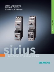
<strong>System</strong>-based switching,protecting, starting.SIRIUS <strong>Modular</strong> <strong>System</strong>.sirius
Everything for the electrical cabinet:SIRIUS <strong>Modular</strong> <strong>System</strong>.ContentsS00 structureS00 selection and ordering data:Circuit breakers, contactors,soft starters, overload relaysPress ShopMaster control roomS0 structureS0 selection and ordering data:Circuit breakers, contactors,soft starters, overload relaysS2 structureS2 selection and ordering data:Circuit breakers, contactors,soft starters, overload relaysS3 structurePower distributionBody ShopPaint ShopFinal AssemblyPowertrain/AssemblyS3 selection and ordering data:Circuit breakers, contactors,soft starters, overload relaysS6, S10, S12 structureS6, S10, S12 selection andordering data:Contactors, overload relays, soft startersFuseless load feedersInfeed systemPressing, equipping, transporting. These functionsrun in many automated production environments.You’ll find everything that you need to switch,protect and start motors with the extensive portfolioof the modular SIRIUS system.Everything. Easy. SIRIUS.Reversing combinationsup to 45 kWStar-delta combinationsup to 75 kWSafety-related load feedersAccessories
Everything. <strong>System</strong>-based. SIRIUS <strong>Modular</strong> <strong>System</strong>.When configuring electrical cabinets everything must proceed quickly, simply,flexibly using minimum space. How can all of this be done? With our uniquemodular system. This offers you everything that you need to switch, protectand start motors and plants. This means a modular range of standard componentsup to 250 kW/400 V in just 7 sizes. All of the components are optimallyharmonized with one another and can be combined easily. They also use thesame range of accessories. Industrial controls really can be this simple!Ongoing development and continuous innovation ensure that our customers –today and tomorrow – are best equipped with SIRIUS, and profit from costeffectivesolutions. All of the components of the SIRIUS modular systemdistinguish themselves due to their space-saving design and high degree offlexibility. Engineering, mounting & installation, wiring and maintenance canbe simply implemented and in a time-saving fashion. It doesn’t make anydifference if you wish to configure your load feeders with circuit breakers oroverload relays, contactors or soft starters – SIRIUS always has the optimumproduct for your particular application.The advantages of the SIRIUS modular system at a glanceLoad feeders<strong>Modular</strong> designVersions and sizesAccessoriesDesignCommunicationService/maintenanceApprovalsMountingSpring-loaded terminalsServiceEnvironmental issuesDesignUp to 250 kW/400 V – can be simply realized using standard deviceEverything fits together and can be combined as necessaryCost-effective and flexible with 7 compact sizesOptimum degree of variance using standard accessories for all devicesFast commissioning, short equipping times, simple wiringCan be connected to AS-Interface and PROFIBUS DPExtremely long service life, reliable and low maintenanceApproved and certified worldwide – e.g. IEC, UL, CSA, CCC,marine engineeringScrewed or snapped-on for permanent, safe and reliable mountingFast, safe reliable connection, vibration-proof and maintenance-freeShort delivery times include spare parts due to the global logisticalnetworkEnvironmentally-compatible production and materials, can be recycled,low power lossClear, ergonomic and has received the iF Product Design Award
An overview of theSIRIUS <strong>Modular</strong> <strong>System</strong>.Circuit breakersSENTRON 3VLContactorsOverload relaysSoft startersS00 S0 S2 S3 S6 S10 S12
Switching. Protecting. Starting.The componentsof the SIRIUS <strong>Modular</strong> <strong>System</strong>.Far more than ON/OFF: SIRIUS 3RV circuit breakersSIRIUS 3RV circuit breakers (MSP) are compact, current-limitingcircuit breakers. They guarantee safe reliable shutdown whenshort circuits occur and protect loads and plants against overload.Furthermore, they are suitable for operationally switching loadfeeders with a low operating frequency and safely disconnectingthe plant or system from the line supply when service is beencarried out or changes are being made. SENTRON 3VL circuitbreakers are suitable for applications above 100 A. As infeedand load feeder breaker, they protect plants and motors againstshort circuit and overload.Rugged and reliable: SIRIUS 3RT contactorsDue to their extremely high ruggedness and optimum contactreliability, our contactors switch with supreme confidence.Furthermore, compact electrical cabinets can be configured withhigh packing densities. The reason for this is that the auxiliaryswitch blocks and solenoid protective circuitry are located withinthe envelope contours of the contactors. This makes it easier toexpand the system and saves considerable space in the electricalcabinet.Tripping when things get tough: SIRIUS 3RU and 3RBoverload relaysThe overload relays of the SIRIUS family, available as either thermalor solid-state versions, protect loads connected to the main circuit,as a function of the current, and also protect other switching andprotective devices in the particular load feeder. The SIRIUS 3RB2solid-state overload relays guarantee seamless motor and plantprotection from 0.1 A to 630 A. Due to the wide setting ranges,the current range is covered with a minimum number of versions.Soft starting and stopping: SIRIUS 3RW soft startersSIRIUS 3RW soft starters offer a seamless range that covers all standardand high-feature motor starting applications. Today, it can beused in the widest range of applications to provide the advantagesof soft starting and stopping and for simple, cost-effective implementationof machine concepts.Fast, reliable and user-friendly: spring-loaded technologyYou will have a completely new experience with state-of-the-artspring-loaded technology as it relates to simplicity and speed.These screwless terminals reduce connection times by up to 75%,and eliminate wiring mistakes. They can stand up to the toughestconditions due to the vibration and shockproof design. And theyare virtually maintenance-free. It is no surprise that we are alreadyusing innovative spring-loaded technology for most of the SIRIUSmodular system.
More about theSIRIUS <strong>Modular</strong> <strong>System</strong>.Straight ahead: The 3RA11 direct starter Phases interchanged: The 3RA12 reversing starter Two stages – one start:The 3RA14 star-delta combinationReady for immediate use:Pre-wired SIRIUS load feedersLoad feeders start loads using a combination of protectiveand switching functions. Generally, a multiple number ofcomponents is required to implement every type of starter.In order to reduce time and costs – and especially to minimizedowntimes – we offer you a wide range of pre-wiredstarter solutions:• Direct starters up to 22 kW – the optimum startercombination for all motors• Reversing starters up to 11 kW – the matchingcombination for reversing motors• Star-delta combinations up to 75 kW – the solution forrunning-up motors in stages• Soft starters – when soft starting and stopping is required• Safe 3RA71 load feeders – pre-mounted, wired andcertified for the highest safety categories. Real stars thatreduce time and wiring mistakes
User-friendly power infeed and distribution:SIRIUS infeed systemThe SIRIUS infeed system allows power to be fed and distributedto a group of several circuit-breakers or complete load feeders in auser-friendly fashion. These devices belong to the modular SIRIUSsystem and are available with spring-loaded terminals for powerratings up to 5.5 kW at 400 V AC.If you prefer devices with classic screw terminals, then circuit-breakersand contactors are even available up to sizes S00 and S0. This meansthat the SIRIUS infeed system can be used for all motor feeders up to11 kW. Using a terminal block, in addition to the SIRIUS circuit-breakers,additional 1/2/3-pole components – such as relays and miniature circuit-breakers– can be integrated.Design highlights• New degree of flexibility when configuring and extending the system• Integration of motor feeders with screw and springloadedterminals possible• Maximum current rating of 80 A• Additional 1-, 2- or 3-pole components can beadditionally integrated using the terminal block• Either infeed from the left or right up to conductor cross-sections of 25 mm 2• Mounting time savings by using simple plug-in connections• More free space in the control cabinet as a result of theextremely compact design• High vibration strength, especially for controls withspring-loaded terminals• Optional wiring duct between feeders
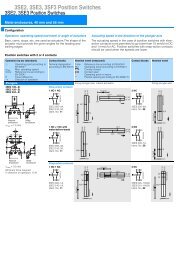
S00 designDirect startReversing startAssembly kit15for busbar mounting40 mm: 3RA19 13-1C17660 mm: 3RA19 13-1Dcomprising:1 wiring kit 44271 busbar adapter 61 controlgear support2 link wedges 752333444VersionOrder No.VersionOrder No.1Size S00 circuit breaker1Size S00 circuit breaker2Link module AC 3RA19 11-1AA002Connector3RA19 11-1AA003Size S00 contactor32, Size S00 contactorsFor busbar mounting (alternative)Busbar adapter 40 mm 8US10 51-5DM0760 mm 8US12 51-5DM074Wiring kit: 3RA19 13-2Aupper link module,lower link module,2 connecting clips,mechanical interlock(these can be eliminated)For rail mounting (diagram)For busbar mounting (diagram)Directly snapped onto a mounting rail without adapter5Controlgear support 40 mm 8US10 50-5AM0060 mm 8US12 50-5AM006Busbar adapter 40 mm 8US10 51-5DM0760 mm 8US12 51-5DM077Link wedges(1 Order No. = 100 wedges)8US19 98-1AA00For rail mounting (alternative)Directly snapped onto mounting rails without adapter
S00 selection and ordering data3-phasemotorAC-3/400 V[kW] [A]0.04 0.140.06 0.20.06 0.20.09 0.30.09 0.30.12 0.40.18 0.60.18 0.60.25 0.80.37 1.10.55 1.50.75 1.90.75 1.91.1 2.71.5 3.61.5 3.62.2 5.23 6.84 95.5 11.5Circuit breakers (MSP) Contactors Soft startersOverload relaysSettingrangeCLASS 10[A]Order No.0.11 – 0.16 3RV10 11-0AA100.14 – 0.2 3RV10 11-0BA100.18 – 0.25 3RV10 11-0CA100.22 – 0.32 3RV10 11-0DA100.28 – 0.4 3RV10 11-0EA100.35 – 0.5 3RV10 11-0FA100.45 – 0.63 3RV10 11-0GA100.55 – 0.8 3RV10 11-0HA100.7 – 1 3RV10 11-0JA100.9 – 1.25 3RV10 11-0KA101.1 – 1.6 3RV10 11-1AA101.4 – 2 3RV10 11-1BA101.8 – 2.5 3RV10 11-1CA102.2 – 3.2 3RV10 11-1DA102.8 – 4 3RV10 11-1EA103.5 – 5 3RV10 11-1FA104.5 – 6.3 3RV10 11-1GA105.5 – 8 3RV10 11-1HA107 – 10 3RV10 11-1JA109 – 12 3RV10 11-1KA10Control Aux- Order No.supply iliaryvoltage switchesAC 230 V, 50/60 Hz 1NC1NO3RT10 15-1AP023RT10 15-1AP01DC 24 V 1NC 3RT10 15-1BB421NOAC 230 V, 50/60 Hz 1NC1NO3RT10 15-1BB413RT10 16-1AP023RT10 16-1AP01DC 24 V 1NC 3RT10 16-1BB421NO3RT10 16-1BB41AC 230 V, 50/60 Hz 1NC 3RT10 17-1AP021NO 3RT10 17-1AP01DC 24 V 1NC 3RT10 17-1BB421NO 3RT10 17-1BB41ControlsupplyvoltageRated Order No.operatingcurrent 1) leAC/DC 110–230 V6 3RW30 14-1CB14AC/DC DC 24 V6 3RW30 14-1CB04AC/DC 110–230 VAC/DC 24 V9 3RW30 16-1CB149 3RW30 16-1CB04SettingrangeCLASS 10[A]ThermalOrder No.0.11 – 0.16 3RU11 16-0AB00.14 – 0.2 3RU11 16-0BB00.18 – 0.25 3RU11 16-0CB00.22 – 0.32 3RU11 16-0DB00.28 – 0.4 3RU11 16-0EB00.35 – 0.5 3RU11 16-0FB00.45 – 0.63 3RU11 16-0GB00.55 – 0.8 3RU11 16-0HB00.7 – 1 3RU11 16-0JB00.9 – 1.25 3RU11 16-0KB01.1 – 1.6 3RU11 16-1AB01.4 – 2 3RU11 16-1BB01.8 – 2.5 3RU11 16-1CB02.2 – 3.2 3RU11 16-1DB02.8 – 4 3RU11 16-1EB03.5 – 5 3RU11 16-1FB04.5 – 6.3 3RU11 16-1GB05.5 – 8 3RU11 16-1HB07 – 10 3RU11 16-1JB09 – 12 3RU11 16-1KB01) For rated device operating voltageVe: 200–460 V (Ve: 460–575 V refer to Catalog)2) When using tripping class CLASS 20 refer to theinformation in the engineering support“Engineering SIRIUS fuseless load feeders” andalso in the CatalogSettingrange[A]Solid-stateOrder No.0,1 – 0,4 3RB2 1 - RB00,32 – 1,25 3RB2 1 - NB01 – 4 3RB2 1 - PB03 –12 3RB2 1 - SB0Class 10 0 6 1Class 20 0 6 2Class 5...30* 1 3 4* With ground fault detection(can be activated) andelectrical remote reset.S00
S0 designDirect startReversing startAssembly kit11687for busbar mounting40 mm: 3RA19 13-1C60 mm: 3RA19 13-1Dcomprising:1 wiring kit 581 busbar adapter641 controlgear support2 link wedges 872232Assembly kitfor rail mounting3RA19 23-1Bcomprising:31 wiring kit52 rail adapter2 side modules4 link wedges 85VersionOrder No.1Size S0 circuit breaker123VersionOrder No.Size S0 circuit breakerLink module AC 3RA19 21-1AA00DC3RA19 21-1BA00Size S0 contactor23452, Size S0 connectorsMechanical interlock 3RA19 24-2BLink module AC 3RA19 21-1AA00DC3RA19 21-1BA00Wiring kit: 3RA19 23-2Aupper link module,lower link moduleFor busbar mounting (alternative)For busbar mounting (diagram)Busbar adapter 40 mm 8US10 51-5DM0760 mm 8US12 51-5DM07For rail mounting (diagram)67Controlgear support 40 mm 8US10 60-5AM0060 mm 8US12 60-5AM00Busbar adapter 40 mm 8US10 51-5DM0760 mm 8US12 51-5DM07Directly snapped onto a mounting rail without adapter8Link wedges (1 Order No. = 100 wedges)8US19 98-1AA00For rail mounting (alternative)Rail adapter3RA19 22-1AA00Side module (1 Order No. = 100 modules) 3RA19 02-1BLink wedges (1 Order No. = 100 wedges)8US19 98-1AA00
S0 selection and ordering data1) For rated device operating voltageVe: 200–460 V (Ve: 460–575 V refer to Catalog)2) When using tripping class CLASS 20 refer to theinformation in the engineering support“Engineering SIRIUS fuseless load feeders” andalso in the Catalog3) Fan available as accessory3-phasemotorAC-3/400 V[kW][A]5.5 11.5Circuit breakers (MSP) Contactors Soft startersOverload relaysSettingrangeCLASS 10Order No.[A]9 – 12.5 3RV10 21-1KA10Control Aux- Order No.supply iliaryvoltage contactsAC 230 V, 50/60 Hz –3RT10 24-1AL20DC 24 V – 3RT10 24-1BB40Control Rated- Order No.supply operatingvoltage current 1)leAC/DC 110–230 V 3)12.5 3RW30 24-1AB14Setting Thermalrange Order No.CLASS 10[A]9 – 12.5 3RU11 26-1KB0Settingrange[A]Solid-stateOrder No.7.5 15.57.5 15.511 – 16 3RV10 21-4AA1014 – 20 3RV10 21-4BA10AC 230 V, 50/60 Hz – 3RT10 25-1AL20DC 24 V – 3RT10 25-1BB40AC/DC 24 V 3) 12.5 3RW30 24-1AB04AC/DC 110–230 V 3)16 3RW30 25-1AB14AC/DC 24 V 3) 16 3RW30 25-1AB0411 – 16 3RU11 26-4AB014 – 20 3RU11 26-4BB06 – 25 2RB2 2 - QB011 2217 – 22 3RV10 21-4CA10AC 230 V, 50/60 Hz – 3RT10 26-1AL20DC 24 V – 3RT10 26-1BB40AC/DC 110–230 V 3)25 3RW30 26-1AB1417 – 22 3RU11 26-4CB0Class 10 0 6 1Class 20 0 6 2Class 5...30* 1 3 411 2220 – 25 3RV10 21-4DA10AC/DC 24 V 3) 253RW30 26-1AB0420 – 25 3RU11 26-4DB0* With ground fault detection(can be activated) andelectrical remote reset.S0
S2 designDirect startReversing startgsße14Hutschieadapter3RA19 3LeistungsschalterBaugröße S2146375Assembly kitfor busbar mounting40 mm: 3RA19 33-1C60 mm: 3RA19 33-1Dcomprising:381 wiring kit 51 busbar adapter6a 51491 controlgear support1 side module 92 link wedges 87ungs-231-1AA002232Assembly kitfor rail mounting31-1BA003RA19 33-1Bcomprising:1 wiring kit53eb5Verdrahtungsbausatz3RA19 33-2Aa oberer Verdrahtungsbausteinb unterer Verdrahtungsbaustein2 rail adapter2 side modules4 link wedges 8VersionOrder No.VersionOrder No.1Size S2 circuit breaker123Size S2 circuit breakerLink module AC 3RA19 31-1AA00DC3RA19 31-1BA00Size S2 contactorFor busbar mounting (alternative)Busbar adapter 40 mm 8US10 61-5FP0860 mm 8US12 61-5FP0823452, Size S2 connectorsMechanical interlock 3RA19 24-2BLink module AC 3RA19 31-1AA00DC3RA19 31-1BA00Wiring kit: 3RA19 33-2Aupper link module,lower link moduleFor busbar mounting (diagram)4For rail mounting (diagram)Rail adapter3RA19 32-1AA0067Controlgear support 40 mm 8US10 60-5AP0060 mm 8US12 60-5AP00Busbar adapter 40 mm 8US10 61-5FP0860 mm 8US12 61-5FP088Link wedges (1 Order No. = 100 wedges)8US19 98-1AA009Side module8US19 98-2MB00For rail mounting (alternative)Rail adapterLink wedges (1 Order No. = 100 wedges)3RA19 32-1AA008US19 98-1AA00
S2 selection and ordering data1) For rated device operating voltageVe: 200–460 V (Ve: 460–575 V refer to Catalog)2) When using tripping class CLASS 20 refer to theinformation in the engineering support“Engineering SIRIUS fuseless load feeders” andalso in the Catalog3) Fan available as accessory3-phasemotorAC-3/400 V[kW][A]Circuit breakers (MSP) Contactors Soft startersOverload relaysSettingrangeCLASS 10[A]Order No.Control Aux- Order No.supply iliaryvoltage contactsControl Rated Order No.supply operatingvoltage current 1)leSettingrangeCLASS 10[A]ThermalOrder No.Settingrange[A]Solid-stateOrder No.15 2922 – 32 3RV10 31-4EA10AC 230 V, 50/60 Hz –3RT10 34-1AL20DC 24 V – 3RT10 34-1BB40AC/DC 110–230 V 3)32 3RW30 34-1AB1422 – 32 3RU11 36-4EB018.5 3522 4122 4128 – 40 3RV10 31-4FA1036 – 45 3RV10 31-4GA1040 – 50 3RV10 31-4HA10AC 230 V, 50/60 Hz – 3RT10 35-1AL20DC 24 V – 3RT10 35-1BB40AC 230 V, 50/60 Hz – 3RT10 36-1AL20DC 24 V – 3RT10 36-1BB40AC/DC 24 V 3) 32 3RW30 34-1AB04AC/DC 110–230 V 3)38 3RW30 35-1AB14AC/DC 24 V 3) 38 3RW30 35-1AB04AC/DC 110–230 V 3)45 3RW30 36-1AB14AC/DC 24 V 3) 4528 – 40 3RU11 36-4FB036 – 45 3RU11 36-4GB040 – 50 3RU11 36-4HB012,5 – 50 3RB2 3 - UB0Class 10 0 6 1Class 20 0 6 2Class 5...30* 1 3 4* With ground fault detection(can be activated) andelectrical remote reset.3RW30 36-1AB04S2
S3 designDirect startReversing start5141675Assembly kitfor rail mounting3RA19 43-1Bcomprising:71 wiring kit 82 rail adapter 53 side modules628476 link wedges 72673238VersionOrder No.VersionOrder No.1Size S3 circuit breaker1Size S3 circuit breaker234Link module AC 3RA19 41-1AA00DC3RA19 41-1BA00Size S3 contactorRail adapter 3RA19 42-1A2342, Size S3 connectorsMechanical interlock 3RA19 24-2BLink module AC 3RA19 41-1AA00DC3RA19 41-1BA005Rail adapter3RA19 42-1AA006Side modules for rail adapters 3RA19 02-1B(1 Order No. = 10 adapters)7Link wedge (1 Order No. = 100 wedges)8US19 98-1AA008Wiring kit: 3RA19 43-2Aupper link module,lower link module
S3 selection and ordering data1) For rated device operating voltageVe: 200–460 V (Ve: 460–575 V refer to Catalog)2) When using tripping class CLASS 20 refer to theinformation in the engineering support“Engineering SIRIUS fuseless load feeders” andalso in the Catalog3) Fan available as accessory3-phasemotorAC-3/400 V[kW][A]Circuit breakers (MSP) Contactors Soft startersOverload relaysSettingrangeCLASS 10[A]Order No.Control Aux- Order No.supply iliaryvoltage switchesControlsupplyvoltageRatedoperatingcurrent 1)leOrder No.SettingrangeCLASS 10[A]ThermalOrder No.Settingrange[A]Solid-stateOrder No.30 5545 – 63 3RV10 41-4JA10AC 230 V, 50/60 Hz –3RT10 44-1AL20DC 24 V – 3RT10 44-1BB40AC/DC 110–230 V 3)63 3RW30 44-1AB1445 – 63 3RU11 46-4JB037 6745 8045 8057 – 75 3RV10 41-4KA1070 – 90 3RV10 41-4LA1080 – 100 3RV10 41-4MA10AC 230 V, 50/60 Hz – 3RT10 45-1AL20DC 24 V – 3RT10 45-1BB40AC 230 V, 50/60 Hz – 3RT10 46-1AL20DC 24 V – 3RT10 46-1BB40AC/DC 24 V 3) 63 3RW30 44-1AB04AC/DC 110–230 V 3)75 3RW30 45-1AB14AC/DC 24 V 3) 75 3RW30 45-1AB04AC/DC 110–230 V 3)100 3RW30 46-1AB14AC/DC 24 V 3) 10057 – 75 3RU11 46-4KB070 – 90 3RU11 46-4LB080 – 100 3RU11 46-4MB025 – 100 3RB2 4 - EB0Class 10 0 6 1Class 20 0 6 2Class 5...30* 1 3 4* With ground fault detection(can be activated) andelectrical remote reset.3RW30 46-1AB04S3
S6, S10, S12 selection and ordering dataS6ContactorsOverload relaysSoft starters3-phasemotorAC-3/400 V[kW][A]Electromagnetic Control Auxiliary Contactor Vacuumoperating supply switches Order No. contactormechanism voltage Order No.[AC/DC V]Setting Solid-state Versionrange Order No.CLASS 10[A]ControlsupplyvoltageRatedoperatingcurrent 1)le [A]Order No.55 115Conventional 220–240 2NO + 2NC 3RT1054-1AP36 –Electronic– for 24 V DC PLC output 200–277 2NO + 2NC 3RT1054-1NP36 –– for 24 V DC PLC output w/ RLT 3) 200–277 1NO + 1NC 3RT1054-1PP35 –– with AS-i interface and RLT 3) 200–277 1NO + 1NC 3RT1054-1QP35 –75 150Conventional 220–240 2NO + 2NC 3RT1055-6AP36 –Electronic– for 24 V DC PLC output 200–277 2NO + 2NC 3RT1055-6NP36 –– for 24 V DC PLC output w/ RLT 3) 200–277 1NO + 1NC 3RT1055-6PP35 –– with AS-i interface and RLT 3) 200–277 1NO + 1NC 3RT1055-6QP35 –50 – 200 3RB2 5 - FW2with straightthroughtransformer50 – 200 3RB2 5 - FC2 with busbarconnectionAC 230 V 134 3RW40 55-6BB44AC 115 V 134 3RW40 55-6BB34AC 230 V 162 3RW40 56-6BB4490 185Conventional 220–240 2NO + 2NC 3RT1056-6AP36 –Electronic– for 24 V DC PLC output 200–277 2NO + 2NC 3RT1056-6NP36 –– for 24 V DC PLC output w/ RLT 3) 200–277 1NO + 1NC 3RT1056-6PP35 –– with AS-i interface and RLT 3) 200–277 1NO + 1NC 3RT1056-6QP35 –Class 10 0 6 1Class 20 0 6 2Class 5...30* 1 3 4* With ground fault detection(can be activated) andelectrical remote reset.AC 115 V 162 3RW40 56-6BB34
S10110 225Conventional 220–240 2NO + 2NC 3RT1064-6AP36 3RT1264-6AP36Electronic– for 24 V DC PLC output 200–277 2NO + 2NC 3RT1064-6NP36 3RT1264-6NP36– for 24 V DC PLC output w/ RLT 3) 200–277 1NO + 1NC 3RT1064-6PP35 –– with AS-i interface and RLT 3) 200–277 1NO + 1NC 3RT1064-6QP35 –55 – 250 3RB2 6 - GC2 with busbarconnectionAC 230 V 230 3RW40 73-6BB44132 265160 300Conventional 220–240 2NO + 2NC 3RT1065-6AP36 3RT1265-6AP36Electronic– for 24 V DC PLC output 200–277 2NO + 2NC 3RT1065-6NP36 3RT1265-6NP36– for 24 V DC PLC output w/ RLT 3) 200–277 1NO + 1NC 3RT1065-6PP35 –– with AS-i interface and RLT 3) 200–277 1NO + 1NC 3RT1065-6QP35 –Conventional 220–240 2NO + 2NC 3RT1066-6AP36 3RT1266-6AP36Electronic– for 24 V DC PLC output 200–277 2NO + 2NC 3RT1066-6NP36 3RT1266-6NP36– for 24 V DC PLC output w/ RLT 3) 200–277 1NO + 1NC 3RT1066-6PP35 –– with AS-i interface and RLT 3) 200–277 1NO + 1NC 3RT1066-6QP35 –160 – 630 3RB2 6 - MC2 with busbarconnectionAC 115 V 230 3RW40 73-6BB34AC 230 V 280 3RW40 74-6BB44AC 115 V 280 3RW40 74-6BB34S12200 400250 500Conventional 220–240 2NO + 2NC 3RT1075-6AP36 3RT1275-6AP36Electronic– for 24 V DC PLC output 200–277 2NO + 2NC 3RT1075-6NP36 3RT1275-6NP36– for 24 V DC PLC output w/ RLT 3) 200–277 1NO + 1NC3RT1075-6PP35 –– with AS-i interface and RLT 3) 200–277 1NO + 1NC 3RT1075-6QP35 –Conventional 220–240 2NO + 2NC 3RT1076-6AP36 3RT1276-6AP36Electronic– for 24 V DC PLC output 200–277 2NO + 2NC 3RT1076-6NP36 3RT1276-6NP36– for 24 V DC PLC output w/ RLT 3) 200–277 1NO + 1NC 3RT1076-6PP35 –– with AS-i interface and RLT 3) 200–277 1NO + 1NC 3RT1076-6QP35 –160 – 630 3RB2 6 - MC2 with busbarconnectionClass 10 0 6 1Class 20 0 6 2Class 5...30 1 3 4* With ground fault detection(can be activated) andelectrical remote reset.AC 230 V 356 3RW40 75-6BB44AC 115 V 356 3RW40 75-6BB44AC 230 V 432 3RW40 76-6BB44AC 115 V 432 3RW40 76-6BB34For applications above 100 A, SIRIUS contactors can be combined with SENTRON 3VL circuit breakers.For more detailed information please refer to the engineering brochure “Engineering SIRIUS fuseless load feeders”.1) For rated device operating voltageVe: 200–460 V (Ve: 400–600 V refer to Catalog)2) When using tripping class CLASS 20 refer to the information in theengineering document “Engineering SIRIUS fuseless load feeders”and as well as in the Catalog3) RLT: Remaining lifetimeSENTRON 3VL circuit breakers are suitable for fuselessshort circuit and overload protection for softstarters from Size S6. For more detailed information,please refer to the Catalog.S6, S10, S12
Completely mounted/assembled load feedersFuseless load feeders3-phase motorAC-3/400 V[kW][A]Setting range,thermaloverloadrelease3RA coordinationtype 2230 V AC direct3RA coordinationtype 2230 V AC reversingSize3RA coordinationtype 1230 V AC direct3RA coordinationtype 1230 V AC reversingSize0.06 0.20.06 0.20.09 0.30.09 0.30.12 0.40.18 0.60.18 0.60.25 0.60.37 1.10.55 1.50.75 1.90.14 – 0.20.18 – 0.250.22 – 0.320.28 – 0.40.35 – 0.50.45 – 0.630.55 – 0.80.7 – 10.9 – 1.251.1 – 1.61.4 – 23RA11 10-0BA15-1AP03RA11 10-0CA15-1AP03RA11 10-0DA15-1AP03RA11 10-0EA15-1AP03RA11 10-0FA15- 1AP03RA11 10-0GA15-1AP03RA11 10-0HA15-1AP03RA11 10-0JA15 -1AP03RA11 10-0KA15-1AP03RA11 10-1AA15-1AP03RA11 10-1BA15-1AP03RA12 10-0BA15-0AP03RA12 10-0CA15-0AP03RA12 10-0DA15-0AP03RA12 10-0EA15-0AP03RA12 10-0FA15- 0AP03RA12 10-0GA15-0AP03RA12 10-0HA15-0AP03RA12 10-0JA15- 0AP03RA12 10-0KA15-0AP03RA12 10-1AA15-0AP03RA12 10-1BA15-0AP0S00Coordination type 2also fulfillscoordination type 1Coordination type 2also fulfillscoordination type 1S000.75 1.91.1 2.71.5 3.61.5 3.62.2 5.23 6.84 95.5 11.57.5 15.57.5 15.511 2211 2211 2215 2918.5 3522 4122 411.8 – 2.52.2 – 3.22.8 – 43.5 – 54.5 – 6.35.5 – 87 – 109 – 12.511 – 1614 – 2017 – 2220 – 2518 – 2522 – 3228 – 4036 – 4540 – 503RA11 20-1CA24-0AP03RA11 20-1DA24-0AP03RA11 20-1EA24-0AP03RA11 20-1FA24 -0AP03RA11 20-1GA24-0AP03RA11 20-1HA24-0AP03RA11 20-1JA26 -0AP03RA11 20-1KA26-0AP03RA11 20-4AA26-0AP03RA11 20-4BA26-0AP03RA11 20-4CA26-0AP03RA11 30-4DB34-0AP03RA11 30-4EB34 -0AP03RA11 30-4FB35 -0AP03RA11 30-4GB36-0AP03RA11 30-4HB36-0AP03RA12 20-1CB24- 0AP03RA12 20-1DB24-0AP03RA12 20-1EB24- 0AP03RA12 20-1FB24- 0AP03RA12 20-1GB24-0AP03RA12 20-1HB24-0AP03RA12 20-1JB26- 0AP03RA12 20-1KB26-0AP03RA12 20-4AB26-0AP03RA12 20-4BB26- 0AP03RA12 20-4CB26- 0AP0S0S23RA11 10-1CA15-1AP03RA11 10-1DA15-1AP03RA11 10-1EA15-1AP03RA11 10-1FA15- 1AP03RA11 10-1GA15-1AP03RA11 10-1HA15-1AP03RA11 10-1JA16- 1AP03RA11 10-1KA17-1AP03RA11 20-4AA25-0AP03RA11 20-4BA25-0AP03RA11 20-4CA26-0AP03RA11 20-4DA26-0AP03RA12 10-1CA15-0AP03RA12 10-1DA15-0AP03RA12 10-1EA15-0AP03RA12 10-1FA15- 0AP03RA12 10-1GA15-0AP03RA12 10-1HA15-0AP03RA12 10-1JA16- 0AP03RA12 10-1KA17-0AP03RA12 20-4AB25-0AP03RA12 20-4BB25- 0AP03RA12 20-4CA26-0AP03RA12 20-4DB26-0AP0S00S0S0S2
Infeed systemVersionOrder No.3-phase busbars13-phase busbars with infeed leftincl. 3RV19 17-6A end cover for 2 switches 3RV19 17-1A3-phase busbars with infeed rightincl. 3RV19 17-6A end cover for 2 switches 3RV19 17-1E23-phase busbars to expand the systemincl. 3RV19 17-5BA00 expansion connector for 2 switches 3RV19 17-4A3-phase busbars to expand the systemincl. 3RV19 17-5BA00 expansion connector for 3 switches 3RV19 17-4BConnection plug5Connection plugto connect to the circuit breaker S0, screw 1 unit 3RV19 17-5CA0010 units 3RV19 17-5CS00, spring-loaded terminals 1 unit 3RV19 17-5AA0010 units 3RV19 17-5AS0, screw 1 unit 3RV19 27-5AA0010 units 3RV19 27-5AAccessories6Contactor socket to configure direct or reversing starters 1 unit 3RV19 17-7AA0010 units 3RV19 17-7A7Terminal block to integrate1, 2 or 3-pole components 3RV19 17-5D123a3b45673-phase busbar with infeed at the left, 3RV19 17-1A3-phase busbar to expand the system, 3RV19 17-4BExtension plug, 3RV19 17-5BA00Wider extension plug, 3RV19 17-5EEnd cover, 3RV19 17-6AConnection plug, 3RV19-17-5AA00Contactor socket, 3RV19-17-AA00Terminal block, 3RV19-17-5D3b3aMounting rail to integrate other devices into the system,e.g. 5SY cable protection circuit breakersWider extension plug 3RV19 17-5ESpare partsExpansion plugas spare part3RV19 17-5BA004End coveras spare part 3RV19 17-6AFuseless load feeders,infeed system
Reversing combinations and Star-delta combinationsReversing combinations up to 45 kWStar-delta combinations up to 75 kWS00S00Reversing combinations3-phase motor Size Pre-wired andAC-3/400 Vtestedfor 230 V AC, 50/60 Hz[kW] [A] Order No.5.5 7 S00 3RA13 15-8XB30-1AP012 S0 3RA13 24-8XB30-1AL27.5 9 S00 3RA13 16-8XB30-1AP017 S0 3RA13 25-8XB30-1AL211 12 S00 3RA13 17-8XB30-1AP025 S0 3RA13 26-8XB30-1AL215 32 S2 3RA13 34-8XB30-1AL218.5 40 S2 3RA13 35-8XB30-1AL222 50 S2 3RA13 36-8XB30-1AL230 65 S3 3RA13 44-8XB30-1AL237 37 S3 3RA13 45-8XB30-1AL245 95 S3 3RA13 46-8XB30-1AL2Contactors combinations3-phase motor Size Pre-wired andAC-3/400 Vtestedfor 230 V AC, 50/60 Hz[kW] [A] Order No.5.5 12 S00-S00-S00 3RA14 15-8XB21-1AP07.5 17 S00-S00-S00 3RA14 16-8XB21-1AP011 25 S0-S0-S0 3RA14 23-8XC21-1AL215/18.5 32/40 S0-S0-S0 3RA14 25-8XC21-1AL222/30 50/65 S2-S2-S0 3RA14 34-8XC21-1AL237 80 S2-S2-S2 3RA14 35-8XC21-1AL245 86 S2-S2-S2 3RA14 36-8XC21-1AL255 115 S3-S3-S2 3RA14 44-8XC21-1AL275 150 S3-S3-S2 3RA14 45-8XC21-1AL2
Completely assembled load feedersSafety-related load feeders3-phase motorAC-3/400 V[kW][A]Setting range,thermaloverloadreleaseCoordination type 2230 V ACCategory 3according to EN 954-1Coordination type 224 V DCSize0.04 0.160.06 0.20.06 0.20.09 0.30.09 0.30.12 0.40.18 0.60.18 0.60.25 0.80.37 1.10.55 1.50.75 1.90.11 – 0.160.14 – 0.20.18 – 0.250.22 – 0.320.28 – 0.40.35 – 0.50.45 – 0.630.55 – 0.80.7 – 10.9 – 1.251.1 – 1.61.4 – 23RA71 01-0AA17-0AL23RA71 01-0BA17-0AL23RA71 01-0BA17-0AL23RA71 01-0DA17-0AL23RA71 01-0EA17-0AL23RA71 01-0FA17-0AL23RA71 01-0GA17-0AL23RA71 01-0HA17-0AL23RA71 01-0JA17-0AL23RA71 01-0KA17-0AL23RA71 01-1AA17-0AL23RA71 01-1BA17-0AL23RA71 1-0AA17-0AB43RA71 1-0BA17-0AB43RA71 1-0BA17-0AB43RA71 1-0DA17-0AB43RA71 1-0EA17-0AB43RA71 1-0FA17-0AB43RA713RA713RA713RA713RA713RA711-0GA17-0AB41-0HA17-0AB41-0JA17-0AB41-0KA17-0AB41-1AA17-0AB41-1BA17-0AB4S000.75 1.91.1 2.71.5 3.61.5 3.62.2 5.23 6.84 95.5 11.57.5 15.57.5 15.511 221.8 – 2.52.2 – 3.22.8 – 43.5 – 54.5 – 6.35.5 – 87 – 109 – 12.511 – 1614 – 2017 – 223RA71 02-1CA26-0AL23RA71 02-1DA26-0AL23RA71 02-1EA26-0AL23RA71 02-1FA26-0AL23RA71 02-1GA26-0AL23RA71 02-1HA26-0AL23RA71 02-1JA26-0AL23RA71 02-1KA26-0AL23RA71 02-4AA26-0AL23RA71 02-4BA26-0AL23RA71 02-4CA26-0AL23RA713RA713RA713RA713RA713RA713RA713RA713RA713RA713RA712-1CA26-0AB42-1DA26-0AB42-1EA26-0AB42-1FA26-0AB42-1GA26-0AB42-1HA26-0AB42-1JA26-0AB42-1KA26-0AB42-4AA26-0AB42-4BA26-0AB42-4CA26-0AB4S0S0011without3RA71 00-5AA26-0AL23RA710-5AA26-0AB4Circuit breaker(contactor-safetycombination)0 Safety electronics as basic unit up to Category 31 Safety electronics as basic unit up to Category 42 Safety electronics as expansion unit3 Safety electronics as expansion unit, time delay 0.05–3 s4 Safety electronics as expansion unit, time delay 0.05–30 sStar-delta combination,reversing combination,safety-related load feeders
Accessoriesoor Circuit -coupling breakers r otary oper ating mecha ni sm sVersion For Size Order No.8Insulated 3-phase busbar systems2743-phase busbars, modular spacing 45 mmfor 2 switches S00, S0 3RV19 15-1ABfor 3 switches3RV19 15-1BBfor 4 switches3RV19 15-1CBfor 5 switches3RV19 15-1DBConnectorfrom S0 to S00 S00, S0 3RV19 15-5DB3163-phase busbars, modular spacing 55 mmfor 2 switches S2 3RV19 35-1Afor 3 switches 3RV19 35-1Bfor 4 switches 3RV19 35-1CVersion For Size Order No.5NSB00006a3-phase line-side terminal,connection from the topS00 3RV19 15-5AS03RV19 25-5ABS2 3RV19 35-5ADoor-coupling rotary operating mechanismsBlackExtension shaft 130 mm S0, S2, S3 3RV19 26-0BExtension shaft 330 mm 3RV19 26-0Kwith support bracket12345678Transverse auxiliary 1CO S00, S0, S2, S3 3RV19 01-1Dswitch 1NO + 1NC 3RV19 01-1E2NO 3RV19 01-1FTransverse auxiliary 1NO + 1NC S00, S0, S2, S3 3RV19 01-1Aswitch with 2 contacts 2NO 3RV19 01-1B2NC 3RV19 01-1CTransverse auxiliary 2NO + 2NC S00, S0, S2, S3 3RV19 01-1Jswitch with 4 contactsShunt 230 V AC S00, S0, S2, S3 3RV19 02-1DP0releaseUndervoltage release 230 V AC S00, S0, S2, S3 3RV19 02-1AP0Undervoltage release 230 V AC S00 3RV19 12-1CP0with leading S0, S2, S3 3RV19 22-1CP0auxiliary switchesSignaling switch S0, S2, S3 3RV19 21-1MIsolator module S0 3RV19 28-1AS2 3RV19 38-1AMoulded-plastic enclosure for wall mountingWith actuator diaphragmwidth 54 mm S00 3RV19 13-1CA00(e.g. switch + transverse auxiliary switch)width 72 mm S00 3RV19 13-1DA00(e.g. switch + transverse auxiliary switch +auxiliary release)With rotary operating mechanismwidth 54 mm S0 3RV19 23-1CA00(e.g. switch + transverse auxiliary switch)width 72 mm S0 3RV19 23-1DA00(e.g. switch + transverse auxiliary switch +auxiliary release)
AccessoriesContactors S00VersionOrder No.1Contactor (example) 4 kW/400 V, 1NO 3RT10 16-1AP01control supply voltage230 V, 50/60 Hz22331414234Solid-state time-delay block 0.5 – 10 s 3RT19 16-2CH21ON delaySolid-state time-delay block 0.5 – 10 s 3RT19 16-2DH21OFF delayAuxiliary switch block, solid-statetime-delayON delay 0.5 – 10 s 3RT19 16-2ED21OFF delay 0.5 – 10 s 3RT19 16-2FL214451-pole auxiliary switch block, 1NO 3RH19 11-1AA10cable entry from above 1NC 3RH19 11-1AA01561111111115161667892-pole auxiliary switch block, 1NO + 1NC 3RH19 11-1LA11cable entry from above1-pole auxiliary switch block, 1NO 3RH19 11-1BA10cable entry from below 1NC 3RH19 11-1BA012-pole auxiliary switch block, 1NO + 1NC 3RH19 11-1MA11cable entry from below4-pole auxiliary switch block, 2NO + 2NC 3RH19 11-1HA22(terminal designationsacc. to DIN EN 50 012)711102-pole auxiliary switch block, 1NO + 1NC 3RH19 11-1NF11solid-state compatible design(acc. to DIN EN 50 005)811Solder pin adapter for for 4 contactors 3RT19 16-4KA1the basic unit(package)9 9101012 12121314Surge suppressor 127 – 240 V AC 3RT19 16-1JL00with LED (varistor) 12 – 24 V DC 3RT19 16-1JJ00Surge suppressor 127 – 240 V AC 3RT19 16-1BD00without LED (varistor) 24 – 70 V DC 3RT19 16-1BB00Link for paralleling, – 3RT19 16-4BA31(star jumper), 3-pole,without terminal15Link for paralleling, – 3RT19 16-4BB313-pole, with terminal1316Link for paralleling, – 3RT19 16-4BB414-pole, with terminalnd Koppelschützee S00 mit Zubehörschütznischer Zeitrelaisblock, ansprechverzögertfür Schützefür Schütze und Koppelschütze (InterfaceAccessories
AccessoriesContactors S0 – S3245318 1615 171191Version For Size Order No.Contactor, size S0 (example) 7.5 kW/400 V 3RT10 25-1AP00control supply voltage230 V, 50 Hz649710121116 1414 121081234567For sizes S0 to S3:Solid-state time-delay block, ON delay 0.5 – 10 s 3RT19 26-2CH21Solid-state time-delay block, OFF delay 0.5 – 10 s 3RT19 26-2DH21Auxiliary switch block, solid-state time-delayON delay 0.5 – 10 s 3RT19 26-2ED21OFF delay 0.5 – 10 s 3RT19 26-2FL212-pole auxiliary switch block, cable entry from above 1NO + 1NC 3RH19 21-1LA112-pole auxiliary switch block, cable entry from below 1NO + 1NC 3RH19 21-1MA114-pole auxiliary switch block(terminal designations acc. to DIN EN 50 012) 2NO + 2NC 3RH19 21-1HA227513 118615 1319 1714 168910Link for paralleling (star jumper), 3-pole, – S0 3RT19 26-4BA31without terminal S2 3RT19 36-4BA31S33RT19 46-4BA31Link for paralleling, 3-pole, with terminal – S0 3RT19 26-4BB31S23RT19 36-4BB31S33RT19 46-4BB312-pole auxiliary switch block, can be laterally mounted (left or right) 1NO + 1NC S0 – S3 3RH19 21-1DA11(terminal designations acc. to DIN EN 50012)11Single-pole auxiliary switch block (up to 4 can be snapped on) 1NO S0 – S3 3RH19 21-1CA101NC S0 – S3 3RH19 21-1CA0112Mechanical interlock, can be laterally mounted – S0 – S3 3RA19 24-2B181314Mechanical interlock, can be mounted at the front – S0 – S3 3RA19 24-1AWiring connectors at the top and bottom – S0 3RA19 23-2A(reversing operation) – plugging – S2 3RA19 33-2A– S3 3RA19 43-2A15Surge suppressor (varistors), – S0 – S3 3RT19 26-1BD00can be mounted at the top or bottom16Interface for mounting directly onto the contactor coil – S0 – S3 3RT19 26-3AB3117LED module to indicate contactor operation – S0 – S3 3RT19 26-1QT0018Mechanical latching 24 AC/DC S0, S2 3RT19 26-3AB31110 AC/DC S0, S2 3RT19 26-3AF31230 AC/DC S0, S2 3RT19 26-3AP31
AccessoriesContactors S6 – S12Operating mechanism types79131112113364455813181210 1223642191411554565101513RT10 and 3RT14 air contactors,Sizes S6, S10 and S123713 11233RT12 vacuum contactor, Sizes S10 and S12Withdrawable coils for contactors with conventional operatingmechanism 3RT1…-.A..4Withdrawable coils for contactors with electronic operatingmechanism 3RT1…-.N..5Withdrawable coils and laterally mounted module (can be plugged in) forcontactors with electronic operating mechanism and remaining lifetimesignal 3RT1…-.P.. and 2RT1…-.Q123456Version Order No.2-pole auxiliary switch block, can be laterally mounted– 2 nd block (left/right), DIN EN 50 012 1NO + 1NC 3RH19 21-1JA11– 2 nd block (left/right), DIN EN 50 005 1NO + 1NC 3RH19 21-1KA112NO 3RH19 21-1KA204-pole auxiliary switch block, can be mounted at the front– with classification No. 5…8, DIN EN 50 012 2NO + 2NC 3RH19 21-1XA22-0MA0– with classification No. 1…4, DIN EN 50 012 2NO + 2NC 3RH19 21-1HA22Single-pole auxiliary switch block, 1NO 3RH19 21-1CA10can be mounted at the front 1NC 3RH19 21-1CA012-pole auxiliary switch block,1NO + 1NC 3RH19 21-1LA11can be mounted at the frontcable entry from above, DIN EN 50 0052-pole auxiliary switch block,1NO + 1NC 3RH19 21-1MA11can be mounted at the frontcable entry from below, DIN EN 50 005Auxiliary switch block, solid-state time-delay 1NO + 1NC– ON delay, 200–240 V AC 0. … 10 s 3RH19 26-2ED21– OFF delay, 200–240 V AC 0.5 … 10 s 3RH19 26-2FL21Version Order No.78RC element, 127 … 240 V ACConnection cover for S63RT19 56-1CD003RT19 56-4EA1for busbar connection for S10/S12 3RT19 66-4EA19 Connection cover for S6 3RT19 56-4EA2for box terminals for S10/S12 3RT19 66-4EA210 Box terminal block– for S6 to 70 mm 2 3RT19 55-4Gto 120 mm 2 3RT19 56-4G– for S10/S12 to 240 mm 2 3RT19 66-4G11 Link for paralleling for S6 3RT19 56-4BA31for S10/S12 3RT19 66-4BA311213Mechanical interlockWiring connectors, topfor S63RA19 54-2A3RA19 53-2Aand bottom (reversing operation) for S10 3RA19 63-2Aplugging for S12 3RA19 73-2ASize 3-phase Contactor Withdrawable coil for operating mechanismmotor without coil conventional electronicAC-3/400 Vcontrol supply voltage220 … 240 V AC/DC 200 … 277 V AC/DCkW Order No. Order No. Order No.S6 55 3RT10 54-1LA06 3RT19 55-5AP31 3RT19 55-5NP3175 3RT10 55-6LA0690 3RT10 56-6LA06S10 110 3RT10 64-6LA06 3RT19 65-5AP31 3RT19 65-5NP31132 3RT10 65-6LA06160 3RT10 66-6LA06S12 200 3RT10 75-6LA06 3RT19 75-5AP31 3RT19 75-5NP31250 3RT10 76-6LA06Accessories
AccessoriesAccessories for 3RU11 thermal overload relays and 3RB20/21 solid-state overload relaysVersion For Size Order No.Version For Size Order No.Adapter for single mounting for 3RB20/21to separately mount the overload relay, S00 3RB29 13-0AA1screw and snapping onto Rails TH 35 S0 3RB29 23-0AA1Sealable cover for 3RB20/21, transparentto cover the setting elementsfor 3RB20/21 S00 to S10/S12 3RB29 84-0Connecting carrier for individual mounting for 3RU11for separately mounting the overload relay, S00 3RU19 16-3AA01screwed and snapped onto S0 3RU19 26-3AA01TH35 mounting rails. Size S3 also for S2 3RU19 36-3AA01a TH 75 mounting rail S3 3RU19 46-3AA01Terminal Covers for 3RU11 and 3RB20/21Cover for cable lug S3 3RT19 46-4EA1and busbar connection S6 3RT19 56-4EA1S10/S12 3RT19 66-4EA1Cover for box terminals S2 3RT19 36-4EA2S33RT19 46-4EA2S63RT19 56-4EA2S10/S12 3RT19 66-4EA22112Mechanical RESET for 3RU11 und 3RB20/21comprising:Resetting plunger, holder and former S00 to S10/S12 3RU19 00-1APushbutton with extended stroke (12 mm), S00 to S10/S12 3SB30 00-0EA11IP65, 22 mm diameterExtension actuator to equalize S00 bis S10/S12 3SX1335the clearance between a pushbuttonand the release button of the relay.Cover for the screw connection S6 3RT19 56-4EA3between the contactor and S10/S12 3RT19 66-4EA3overload relay withoutbox terminals(1x is required for each combination)Cable release with holder for RESET for 3RU11 und 3RB20/21for holes 6.5 mm diameter length 400 mm S00 to S10/S12 3RU19 00-1Bin the panel; length 600 mm S00 to S10/S12 3RU19 00-1Cmax. panel thickness, 8 mmBox terminal blockfor round and ribbon cables to 70 mm 2 S6 3RT19 55-4Gto 120 mm 2 S6 3RT19 56-4Gto 240 mm 2 S10/S12 3RT19 66-4G
Enclosures for motor starters3-phase motor Enclosure for Size Order No. Components required Qty.AC-3/400 Vdirect starters[kW]5.5 Moulded-plastic enclosure S00 3RE1913-1CB1 Contactor with integrated 3RT10 1.-....1 1for wall mountingauxiliary switch 1NOIP65 degree of protectionwith actuator elements Thermal or solid-state 3RU11 16 resp. 1overload relay 3RB10 1611 Moulded-plastic enclosure S0 3RE1923-1CB2 Contactor 3RT10 2 1for wall mountingIP65 degree of protection Thermal or solid-state 3RU11 26 resp. 1with actuator elements overload relay 3RB10 26Lateral auxiliary switch 3RH19 21-1DA11 11NO/1NC22 Moulded-plastic enclosure S2 3RE1933-1CB3 Contactor 3RT10 3 1for wall mountingIP65 degree of protection Thermal or solid-state 3RU11 36 resp. 1with actuator elements overload relay 3RB10 36Lateral auxiliary switch 3RH19 21-1DA11 11NO/1NC3-phase motor Enclosure for Size Order No. Components required Qty.AC-3/400 Vreversing starters[kW]5.5 Moulded-plastic enclosure S00/S0 3RE1913-2CB3 Contactor 3RT10 1 2for wall mountingIP65 degree of protection Wiring kit for reversing 3RH19 13-2A 1with actuator elementscombinationThermal or solid-state 3RU11 16 resp. 1overload relay 3RB10 16Auxiliary switch 1NO at the front 3RH19 11-1BA10 211 Moulded-plastic enclosure S00/S0 3RE1913-2CB3 Contactor 3RT10 2 2for wall mountingIP65 degree of protection Wiring kit for reversing 3RH19 23-2A 1with actuator elementscombinationDirect and reversing starters in enclosures are also available pre-configured. These include all of the necessary componentsand are pre-wired – with the exception of the overload relay. The overload relay should be selected corresponding to theapplication and must be separately ordered. For more detailed information, please refer to the Catalog.Mechanical interlock 3RH19 24-2B 1Thermal or solid-state 3RU11 26 resp. 1overload relay 3RB10 26Auxiliary switch 1NO at the front 3RH19 21-1CA10 2Accessories
Ordering by fax +49/911/978-3321 CD/Z1226NewsletterAlways up-to-date: Our regularNewsletter gives you current informationabout industrial controls and powerdistribution. Simply register underwww.siemens.com/lowvoltage/newsletterSWITCHINGPROTECTINGSTARTINGSiemens AGSIRIUSIndustrial ControlsSIRIUSSwitchingSIRIUSProtectingSIRIUSStartingSIRIUSInfeed systemCompany/DepartmentNameStreet, Postal Code/CityTelephone/FaxE-mailAutomation and DrivesLow-Voltage Controls and DistributionP.O. Box 48 48, 90327 NUREMBERG, GERMANYPlease send the selected informationto the following address:SIRIUSSolid-stateswitching devicesSIRIUSSoft startersSIRIUS Engineeringload feederswww.siemens.com/lowvoltage/technical-assistancewww.siemens.com/siriusSIMATICET 200proSIRIUSMotor starterMONITORING ANDCONTROLLINGDETECTINGCOMMANDINGAND SIGNALINGSUPPLYINGENGINEERINGSIRIUSAND MORESIRIUSMotor managementsystem SIMOCODE proSIRIUSDetectingSIRIUS Commandingand signalingSIRIUS Pushbuttons andindicator lightsSIRIUSSupplyingSIVENTFansMotor starter ESSoft starter ESSIRIUS SafetyIntegratedECOFASTSIRIUSRelaysSIRIUSSafety RelaysSIRIUSPosition switchesSIRIUS Signaling columns andintegrated signal lampsSIRIUSCable-operated switchesSIDACReactors & filtersSIDAC & SIVENTSolutionsSIMOCODE ESAS-InterfaceSIRIUS <strong>Modular</strong> systemSIRIUS Connection systemsThe information provided in this brochure contains merely generaldescriptions or characteristics of performance which in case of actualuse do not always apply as described or which may change as aresult of further development of the products. An obligation toprovide the respective characteristics shall only exist if expresslyagreed in the terms of contract.All product designations may be trademarks or product names ofSiemens AG or supplier companies whose use by third parties for theirown purposes could violate the rights of the owners.Subject to change without prior notice 03/06 Order No. E20001-A380-P302-V3-7600 I Dispo 27601 I 21C9389 SGSR.52.6.04 PA 03065.0 I Printed in Germany I © Siemens AG 2006 PUBLICIS