Proportional
Proportional
Proportional
- No tags were found...

You also want an ePaper? Increase the reach of your titles
YUMPU automatically turns print PDFs into web optimized ePapers that Google loves.
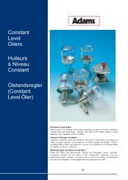
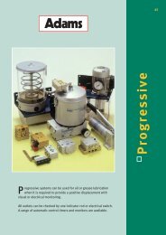
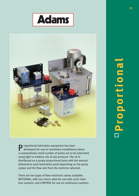
31Adams <strong>Proportional</strong><strong>Proportional</strong> lubrication equipment has beendeveloped for use on machinery installations wherea comparatively small number of points are to be lubricatedusing light to medium oils at low pressure. The oil isdistributed on a purely proportional basis with the amountdelivered to each lubrication point depending on the pumpoutput and the flow rate from the restrictor selected.There are two types of flow restrictors valves available.METERING, with non return valve for use with cyclic totalloss systems, and CONTROL for use on continuous systems.
32Adams<strong>Proportional</strong>System Design & Selection of Meter ValvesWhereas the ideal layout for a <strong>Proportional</strong> System would have equal lengths of tubing at every point, this is rarelypossible to achieve and so a selection of metering valves (restrictors) are available to serve the various lubricationpoint requirements.The variation of flow restriction of the small bore pipe-work (typically 4mm O/D) can generally be ignored,providing that the viscosity of the oil does not exceed 100 cSt @ 40°C or that the pipe runs are not excessive.When the layout has been determined, and the position of the pump established, the correct pump must be chosen.This depends entirely on the amount of oil delivery required per pump operation, allowing 5% extra for system lossesdue to nylon tube expansion.Bear in mind that it is the pump output that determines the total volume of oil which is distributed around the system bymeans of the meter valves or control units - hence the name <strong>Proportional</strong>.The selection of the meter valves to suit a particular bearing size is based on the ability of the meter valve flow rate topass sufficient oil to lubricate the bearing in the ‘cycle time’ of the pump. A bearing with twice the oil requirement wouldneed a meter valve of the next size up on the flow rate chart.Always check that the total value for flow rates of meter valves does not exceed the pump output.ExampleSystem for lubricating a total of 20 bearing points. Of these 10 require 2cc (50 drops) per 8 hour shift. 5 require 4cc (100drops) and 5 require 8cc (200 drops) per shift. This adds up to 80cc (2000 drops).Since it is always better to lubricate ‘little and often’ we will consider a cycle time of 30 minutes using an automatic pump.The choice of meter valves for the 3 different bearing sizes is in the ration of 1-2-4, so we may select any three consecutivemeter valve numbers, preferably from the middle of the available range. e.g. FSO. FS1 and FS2To Summarise:- TYPE OF METER VALVE QUANTITY DELIVERY/MIN TOTALFS0 10 0.08cc 0.80ccFS1 5 0.16cc 0.80ccFS2 5 0.32cc 1.60ccTotal delivery for all the meter valves is 3.2cc so the pump delivery every 30 mins. would have to be approx. 5cc whichrequires the pump running time to be set for 1 min. 30 secs. (JNT Type Pump / Timer)The diagram below shows the layout of a typical system for lubricating 13 delivery points on a machine.Schematic1. the pump with its lubricant container2. the main supply line3. the secondary lines4. the meter valves (restrictors)5. the lubrication points or delivery points
<strong>Proportional</strong>Adams33Combined Motorized Pump/Timer with MonitoringBFEFCDG HJKLAPart No. Voltage Res. Rating A B C D E F G H J K LLV 10290 110/230V 2 Lt Alum. 60 Watt 296 146LV 10291 50Hz 2.7 Lt Plas. Intermittent 196 145 125 15 28 12 7 M12x1 85305 155Please state voltage required: 110V or 230VNote: Outlet connectors are available as following:-For 4mm ∅ tube use Adaptor LV 90020 with Washer LV 91825 Tube Nut LV 90440 and Sleeve LV 90540For 6mm ∅ tube use Adaptor LV 90026 with Washer LV 91825 Tube Nut LV 90460 and Sleeve LV 90560For 1/4 BSP Female (to screw in Filter LV 10009) use Adaptor LV 90044 with Washer LV 91825SPECIFICATIONMotor Rating -70 Watt IntermittentPump Lubricant Output - 360 cc/minDelivery Pressure - 6 barInterval Range - variable 2 min to 8 hoursPumping Range - variable 0 to 60 secondsComplete with Low Level & Line Pressure Switches, Manual Override Button.Four L.E.D. Indicators monitoring system condition.Control Timer will give a Lubrication Cycle on initial Switch ‘On’ and will repeat at the preset intervals.Reservoir Oil Levels and System Oil Pressure are continuously monitored and confirmed by Visual Indicators.‘Voltage Free’ connections for Remote Alarms and the facility to Stop the machine are also provided.Anti-vibration mountings for use with above units are shown on Page - 78.
34Adams<strong>Proportional</strong>Electromagnetic Pump & Timer∅ EDGFABCFEATURESFor Single Line <strong>Proportional</strong> lubrication systems, this compact unit consists of:PROGRAMME CONTROLLER WITH:-Pre-Lube function. Manual (Red) override push button.GREEN - (Flashing) LED showing power ON YELLOW - LED showing pump operatingRED - LED Indicating low level, plus (no voltage contact) for remote signal.ELECTROMAGNETIC PISTON PUMP:-Output:- 120cc per minute Pressure:- 3 - 5 barLubricant:- Mineral oil 15 to 100 cSt @ 40° COutlet Port - 5/16 x 24 TPI (UNF) 4 mm ∅ TubePLASTIC RESERVOIR, with Low Level switch. (NO)SPECIFICATIONTIMERInterval range - Adjustable 0.3 to 90 MinsPump run range - Adjustable 0 to 3 MinsMOTORHalfwave Electromagnetic Motor Rating - 70 Watts Protection - Class FVOLTAGELOAD24 V - 50/60 HZ 2.5A110 V - 50/60 HZ 1.7A230 V - 50/60 HZ 0.7APLEASE STATE VOLTAGE REQUIRED WHEN ORDERING. Example: LV 65011/110 = 110 volt supplyPart No. A B C D E F G Reservoir CapacityLV 65011110 127 123 40 210 105 1.2 Lt TranslucentWith TimerLV 65013 136 150 240 76235 180 3 Lt Transparent6.5LV 69661110 127 123 35 170 105 1.2 Lt TranslucentWithout TimerLV 69667 142 152 155 50 202 125 2.7 Lt TranslucentThe above are also available with Normally Closed (NC) low level switch, and without Pre-Lube facility if required.The use of Anti-vibration mountings are recommended, see page 78 for details.
<strong>Proportional</strong>Adams35Motorized Pumps & Reservoir - 3 Phase & Single PhaseCDEBADescriptionThese electrical control units are for supplying Single Line <strong>Proportional</strong> systems. They are made in two series, one ofwhich uses a three-phase 70 W electric motor with double polarity; and the other is a single-phase motor with the samefeatures. The gear-driven pump has a capacity of 380cc/min. Operating pressure is 4-5 bars which can be regulated byadjusting the regulating valve. Tanks come in a range of sizes (see table at foot of page) and are made of eitherthermoplastic or die-cast aluminium. The units are equipped with an electric minimum level switch.PerformanceA typical installation is equipped with a motorised unit and a number of single line meter valves. There is no limit to thenumber of meter valves since either series can deliver up to 380cc./min. It needs a timer control system which providesfor a pause time and a working time, adjusted to suit the desired flow from the meter valves being used. The lubricationcycles are repetitive, alternating with rest periods.Page 20 shows some of the types of timer controls which can be used with these lubrication systems.Technical CharacteristicsMOTOR THREE PHASE SINGLE PHASEPower Frequency 230/400 V - 50 Hz. 110 - 230 V / 50 - 60 Hz.Absorbed Capacity 0.37/0.21A 1.8/0.9ANominal Power 70 W 70 W.RPM 2800/3360 2800/3360Service continuous continuousProtection IP 54 IP 54Insulation class F class FPUMPCapacity 0.36 Lt/minMax. Pressure 4 barSWITCHMin. level switch LMsingle thresholdContactNO at min. levelVoltage250V AC maxMax. Current3AMax. Load120VAProtection IP 65Insulationclass C3 Phase Single Phase Tank Cap.Motor Motor Lt A B C D ELV 63166 LV 63168 2 Alum295155 146LV 63529 LV 63278 2.7 Plastic 298 6.5105LV 63176 LV 67172 5 Alum 248 174 301 218
36Adams<strong>Proportional</strong>Manual Pumps - Operation of Manual PumpThis system may be used with an average gradeof light to medium lubrication oil only.To operate the pump, pull handle slowly to its fullest extent and release.The pump spring returns the plunger, forcing oil through the distributorsand metering valves to the bearings.LV 10224ACABThe pump handle must be allowed to return normally to the staticposition, any force will result in damage to the system.Adams metering valves use capillary elements to control the oil flow.When the pump is operated, pressure is built up in the main lubricationline. The oil passes through the distributors and is passed through themetering valves to the lubrication points. The pressure generated in theaverage layout is approximately 3.5 bar at the pump outlet. The pressurevaries according to the number of metering valves used in the system.Part No. Delivery ReservoirPer Stroke Capacity A B C Dccm LtLV 10224A 7 -40 211 -70LV 63158 6 0.4 78 142 38LV 628021053 To 9LV 63159155*1.2 124168 98LV 631701056 To 18LV 63160 155*LV 63158 / LV 63170 / LV 62802* Measurement with Handle/Lever at full extentIn all cases the outlet connection is seated for 4mm ∅Tube - Use LV 90443 Tube Nut and LV 90540 sleeve.ReservoirCapacity either 0.4 litres or 1.2 litres and made of shock-resistantthermoplastic material.PressureOperating pressure is determined by the thrust of the counter-springand can be anything between 3.5 and 1.5 bar.LubricantsAny lubricant can be used which has a viscosity of between 15and 100 cSt at 40°C.LV 63159 / LV 63160CDAB
<strong>Proportional</strong>Adams37Metering Valves - with Non-Return Valves, for use with Total Loss Cyclic Systems.Line Type - Screwed into Manifold when feeding lubrication point via ‘Tail Pipe’Part No. Flow Rate A B C D EELV 10533 BJ000LV 55000 BJ00LV 55001BJ0LV 55002 BJ1 31 12 9.52 4 5/16LV 55003 BJ2 (3/8”) UNFLV 55004BJ3LV 55005BJ4LV 10534BJ5BAC (AF)D Tube ∅Bearing Type - Screws directly into bearing point (Standard thread 1/8 BSP)Part No. Flow Rate A B C D ED Tube ∅LV 10535 FS000LV 55018 FS00LV 55019FS0LV 55020 FS1 26 7.2 9.52 4 1/8 BSPLV 55021 FS2 (3/8”) TaperLV 55022FS3LV 54158FS4LV 10536FS5AEBC (AF)Above Meter Valves also available in NPT Threads.All above Metering Valves use Tube Nut LV 90743, and Sleeve LV 90840.These fittings are suitable for use with Nylon, Copper and Bundy Tube.Distribution Manifolds for Meter Valves fitted with Non-Return Valvesi.e. Cyclic Total Loss Systems. All Tube Connections are seated for4mm ∅ Tube, use Tube Nut LV 90443 and Sleeve LV 90540.Single SidedPart No. No. of OutletsA B C D E F G H J KLV 95103 1 30.2 17.5LV 95104 2 48.0 33.3LV 95106 4 77.7 65.0 15.9 15.05 12 20 13.65 7.1 5/16 4mmLV 95108 6 109.5 96.8 UNF ∅LV 95110 8 141.3 128.6 tubeLV 95111 10 173.0 160.3LV 95106Double SidedPart No. No. of OutletsA B C D E F G H J KLV 95205 4 46 33.3LV 95206 6 61.9 49.2 15.9 15.05 12 30 23.65 7.1 5/16 4mmLV 95207 8 77.7 65 UNF ∅LV 95208 10 93.7 81 tubeLV 95209 12 109.5 96.8LV 952074mm tubing nuts and sleeves not suppliedMaterial - Aluminium
38Adams<strong>Proportional</strong>Metering Valves - With non-return valveTee Type - use with Junction Fittings shown belowPart No. Flow Rate A B C DLV 55023 FT 00LV 55024 FT 0LV 55025 FT 1 21.43 7.2 7.2 1/8 BSPLV 55026 FT 2 TaperLV 55027 FT 3LV 54159 FT 4ADBCAbove Meter Valves also Available in NPT ThreadsDJunction Headers 3 way and 4 wayAll tube connections are seated for 4 mm ∅ tube,use Tube Nut LV 90443 and Sleeve LV 90540LV 91528ABE5/16 UNFTHREADPart No. WaysA B C D EALV 91528 3LV 91927 3LV 91558 3 17.46 11.9 12.7 6.35 1/8 BSPLV 91529 4LV 91559 4LV 91927AEBLV 91558ACBAAELV 91529AACEALV 91559AAEAD
<strong>Proportional</strong>Adams39Control Units -Without non-return valve, for flow control on Continuous SystemsLine Type - screwed into manifold when feeding lubrication point via ‘Tail Pipe’Part No. Flow Rate A B C D ELV 10121 L1LV 10122 L2LV 10123 L3LV 10124 L4LV 10125 L5 33 9.5 10 4 M8x1LV 10126 L6LV 10127 L7LV 10128 L8LV 10129 L9C HexA/FlatsTHREADED Tube ∅BD Tube ∅ABearing Type - screws directly into bearing point. (standard thread 1/8 BSP)Part No. Flow Rate A B C D ELV 10131 B1LV 10132 B2LV 10133 B3LV 10134 B4LV 10135 B5 30.2 8 10 4 1/8 BSPLV 10136 B6 TaperLV 10137 B7LV 10138 B8LV 10139 B9C HexA/FlatsEBADistribution ManifoldsFor Control Units NOT fitted with non-return valves i.e. Continuous<strong>Proportional</strong> Systems. All Tube Connections are seated for 4mm ∅ Tube,use Tube Nut 36-0500-02 and Sleeve 36-0501-02.Single SidedPart No. No. of A B C D E F G H J KOutletsLV 10080 2 42.9 33.3 4mmLV 10081 4 71 61.9 14.3 14.3 12.7 19 14.3 5.16 M8x1 ∅LV 10082 6 100 90.5 tubeLV 10083 8 129 119ATubing Nut& SleeveCJAC C DJBFixingHolesHEG FDouble SidedPart No. No. of A B C D E F G H J KOutletsLV 10090 4 42.9 33.3 4mmLV 10091 6 57.2 47.6 14.3 14.3 12.7 28.5 23.8 5.16 M8x1 ∅LV 10092 8 71 61.9 tubeATubing Nut& SleeveCJAC C DBFixingHolesHEG F4mm tubing nuts and sleeves not suppliedMaterial - Aluminium
40Adams<strong>Proportional</strong>AccessoriesAngle AdaptorsPart No. Angle A B C D Taper ELV 10148 90° 12.7 8 121/8 BSP 1/8 BSPLV 10149 45° 14.2 8.6 14.2Material - brassFinish - naturalPressure GaugePart No. Pressure Range Diameter ThreadLV 10406 0-10 bar 50 1/8 BSPPressure Switch - with Din Plug to IP 65Part No. Adjustment Range Bar A B ThreadLV 10550 0.15-10 73 27A/F 1/4 BSPABFlow Filters - Outlet filters with sintered bronze filter elementenclosed in an anodised aluminium casing. Entry possible from eitherside depending on design instructions. Can be cleaned by unscrewingthe cap T, taking out the filter element SJ, then washing andblow-drying both items.Part No. Filtration degree Pressure max.bars Flow litres/min.LV 97522 25 micron 12 1.2A B C D F H J40 42 10 1/8 BSP 7 80 25