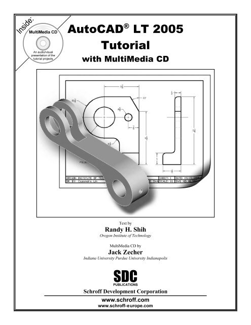
Autocad Tutorial - pdf
Autocad Tutorial - pdf
Autocad Tutorial - pdf
- No tags were found...

Create successful ePaper yourself
Turn your PDF publications into a flip-book with our unique Google optimized e-Paper software.
Geometric Construction Basics 1-3 Note that AutoCAD LT automatically assigns generic names, Drawing X, as newdrawingsCopyrightedare created. In our example, AutoCAD LT opened the graphics windowusing the default system units and assigned the drawing name Drawing1.MaterialCopyrightedMaterialCopyrightedMaterial2. Close the Tool Palettes by clicking once onClose button located the upper right cornerof the window as shown.3. Close the Info Palettes by clicking once on theClose button located at the upper left corner ofCopyrightedthe window as shown.Material
1-4 AutoCAD ® LT 2005 <strong>Tutorial</strong>Drawing Units SetupCopyrightedEvery object we construct in a CAD system is measured in units. We should determinethe value of the units within the CAD system before creating the first geometric entities.Material1. In the pull-down menus, select[Format] [Units]CopyrightedMaterial2. In the Drawing Units dialog box, set the Length Type to Decimal. This will setthe measurement to the default English units, inches.CopyrightedMaterialCopyrighted3. Set the Precision to two digits after the decimal point as shown in the abovefigure.4. Pick OKMaterialto exit the Drawing Units dialog box.
Geometric Construction Basics 1-5Drawing Area SetupCopyrightedNext, we will set up the Drawing Limits; setting the Drawing Limits controls theextents of the display of the grid. It also serves as a visual reference that marks theworking area. It can also be used to prevent construction outside the grid limits andas a plot option that defines an area to be plotted/printed. Note that this setting doesMaterialnot limit the region for geometry construction.1. In the pull-down menus, select[Format] [Drawing Limits]CopyrightedMaterial2. In the command prompt area, near the bottom of the AutoCAD LT drawing screen,the message “Reset Model Space Limits: Specify lower left corner or [On/Off]:” is displayed. Press the Enter key once to accept the defaultCopyrightedcoordinates .Material3. In the command prompt area, the message “Specify upper right corner:” is displayed. Press the ENTER key once to accept the defaultcoordinates .Copyrighted4. On your own, move the graphic cursor near the upper-right comer inside thedrawing areaMaterialand note that the drawing area is unchanged. (The Drawing Limitscommand is used to set the drawing area; but the display will not be adjusted untila display command is used.)
1-6 AutoCAD ® LT 2005 <strong>Tutorial</strong>Copyrighted5. In the pull-down menus, select[View] [Zoom All] The Zoom All command will adjustthe display so that all objects in thedrawing are displayed to be as large asMaterialpossible. If no objects are constructed,the Drawing Limits are used to adjustthe current viewport.6. Move the graphic cursor near the upperright comer inside the drawing area andnote that the display area is updated.CopyrightedUsing the Line CommandMaterial1. Switch ON the Info Palette option in the Helppull-down menu as shown.Copyrighted2. Move the graphics cursor to the first icon in the Draw toolbar.This icon is the Line icon. A help-tip box appears next to thecursor and a brief description of the icon is displayed at thebottomMaterialof the AutoCAD LT drawing screen: “Creates Straightline segments: LINE.”3. Select the icon by clicking once with the left-mouse-button;this will activate the Line command. Notice a brief explanation of the selected commandis displayed in the Active Assistance window. It isCopyrightedhighly recommended that you read the explanationsto gain some insights on the basic assumptions andgeneral procedure of using AutoCAD LT.Material4. In the Active Assistance window, click To drawlines to open the AutoCAD LT Help window and geta more detailed explanation on the procedure.
Geometric Construction Basics 1-7Copyrighted5. Click on Close button located at theInfo Palette window as shown.Materialupper left corner of the AutoCAD LTCopyrighted6. In the command prompt area, near the bottom of the AutoCAD LT drawing screen,the message “_line Specify first point:” is displayed. AutoCAD LT expects us toidentify the starting location of a straight line. Move the graphics cursor insidethe graphics window and watch the display of the coordinates of the graphicscursor at the bottom of the AutoCAD LT drawing screen. The two numbersMaterialrepresent the location of the cursor in the X, and Y directions. We can treat thegraphics window as if it were a piece of paper and we are using the graphicscursor as if it were a pencil with which to draw.CopyrightedCoordinates of the locationof the graphicsMaterialcursor3 25Copyrightedthe actual size or the accuracy of yourMaterial1 4 We will create a freehand sketch of a fivepointstar using the Line command. Createthe sketch by placing the first corner of thestar near the lower left corner of the drawingwindow. Do not be overly concerned withfreehand sketch. This exercise is to give youa feel for the AutoCAD ® LT 2005 userinterface.
1-8 AutoCAD ® LT 2005 <strong>Tutorial</strong>Copyrighted7. We will start at a location about one-third from the bottomof the graphics window. Left-click once to position thestarting point of our first line. This will be point 1 of oursketch. Next move the cursor upward and toward the rightside of point 1. Notice the rubber-band line that followsthe graphics cursor in the graphics window. Left-clickMaterialagain (point 2) and we have created the first line of oursketch.8. Move the cursor to the left of point 2 and create a horizontal line about the samelength as the first line on the screen.9. Repeat the above steps and complete the freehand sketch by adding three moreCopyrightedlines (from point 3 to point 4, point 4 to point 5, and then connect to point 5 back10. Notice that the Line command remains activated even afterMaterialwe connected the last segment of the line to the starting pointto point 1).(point 1) of our sketch. Inside the graphics window, clickonce with the right-mouse-button and a popup menuappears on the screen.11. Select Enter with the left-mouse-button to end the Linecommand. (This is equivalent to hitting the [ENTER] keyon the keyboard. The right-mouse-click brings up moreoptions and we should get used to using the option menu.)Copyrighted12. On your own, move the cursor near point 2 and point 3, and estimate the lengthof the horizontal line by watching the displayed coordinates for each point at thebottom of the screen.MaterialVisual ReferenceThe method we just used to create the freehand sketch is known as the interactivemethod, where we use the cursor to specify locations on the screen. This methodis perhaps the fastest way to specify locations on the screen. However, it is ratherdifficult to try to create a line of a specific length by watching the displayed coordinates.It would be helpful to know what one-inch or one-meter looks like on the screen whilewe are creatingCopyrightedentities. AutoCAD ® LT 2005 provides us with many tools to aid theset increment on the screen.Materialconstruction of our designs. We will use the GRID and SNAP options to get a visualreference as to the size of objects and learn to restrict the movement of the cursor to aThe Status Bar area is located at the bottom of the AutoCAD LT drawing screen. Thewords SNAP, GRID, ORTHO, POLAR, OSNAP, LWT and MODEL appearing to the right
Geometric Construction Basics 1-9of the coordinates are buttons that we can left-click to turn these special options ONand OFF.CopyrightedWhen the corresponding button is highlighted, the specific option is turned on.options. We can toggle the options ON and OFF in the middle of another command.MaterialThese buttons act as toggle switches; each click of the button will toggle the option on oroff. Using the buttons is a quick and easy way to make changes to these drawing aidOption ButtonsGRID ONCopyrighted1. Left-click the GRID button in the Status Bar to turn ON the GRID option. (Noticein the command prompt area, the message “” is also displayed.)MaterialCopyrighted2. Move the cursor inside the graphics window, and estimate the distance betweenthe grid points by watching the coordinates display at the bottom of the screen.Material The GRID option creates a patternCopyrighteddistance in between two dots onMaterial 3.0 inches long.of dots that extends over an areaon the screen. Using the grid issimilar to placing a sheet of gridpaper under a drawing. The gridhelps you align objects andvisualize the distance betweenthem. The grid is not displayedin the plotted drawing. The defaultgrid spacing, which means thethe screen, is 0.5 inches. We cansee that the sketched horizontalline in the above sketch is about
1-10 AutoCAD ® LT 2005 <strong>Tutorial</strong>SNAP ONCopyrighted1. Left-click the SNAP button in the Status Bar to turn ON the SNAP option.Material2. Move the cursor inside the graphics window, and move the cursor diagonally onthe screen. Observe the movement of the cursor and watch the coordinatesCopyrighteddisplay at the bottom of the screen. The SNAP option controls an invisible rectangular grid that restricts cursormovement to specified intervals. When SNAP mode is on, the screen cursor andall input coordinates are snapped to the nearest point on the grid. The default snapMaterialinterval is 0.5 inches, and aligned to the grid points on the screen.3. Click on the Line icon in the Draw toolbar. In the commandprompt area, the message “_line Specify first point:” is displayed.4. Create another sketch of the five-point star with the GRID andSNAP options switched ON.Copyrighted5. Use the right-mouse-button and select Enter in the popup menuto end the Line command if you have not done so.MaterialCopyrightedMaterial
Geometric Construction Basics 1-11Using the ERASERCopyrightedOne of the advantages of using a CAD system is the ability to remove entities withoutleaving any marks. We will erase two of the lines using the Erase command.Material1. Pick Erase in the Modify toolbar. (The icon isthe first icon in the Modify toolbar. The icon isa picture of an eraser at the end of a pencil.)The message “Select objects” is displayed inthe command prompt area and AutoCAD LTwaits for us to select the objects to erase.Copyrighted2. Left-click the SNAP button on the Status Bar to turn OFF the SNAP option sothat we can more easily move the cursor on top of objects. We can toggle theMaterialStatus Bar options ON or OFF in the middle of another command.Copyrighted3. Select any two lines on the screen, and right-mouse-click once to accept theselections. The selected two lines are erased.Material1. Inside the graphics window, click once with the rightmouse-buttonto bring up the popup option menu.Repeat the Last Command2. Pick Repeat Erase, with the left-mouse-button, in thepopup menu to repeat the last command. Notice the otheroptions available in the popup menu.Copyrighted AutoCAD ® LT 2005 offers many options to assist us inaccomplishing this task. Throughout this text, we willemphasize the use of the AutoCAD Heads-up Design TMinterface, which means that we can focus on the screen,Materialnot on the keyboard.
1-12 AutoCAD ® LT 2005 <strong>Tutorial</strong>3. Move the cursor to a location that is above and toward the left side of theentitiesCopyrightedon the screen. Left-mouse-click once to start a corner of a rubber-bandwindow.MaterialFirst cornerCopyrightedMaterialSecond cornerCopyrighted4. Move the cursor toward the and below the entities, and then left-mouse-that are inside the window are selected.Materialclick to enclose all the entities inside the selection window. Notice all entities5. Inside the graphics window, right-mouse-click to proceed with erasing theselected entities. On your own, create a sketch of your choice using the Line command.Experiment with using the different commands we have discussed so far, such asswitching the GRID and SNAP options ON and OFF in the middle of a command. Do not be in a hurry to rush through the tutorials. Build up your CAD skills byfamiliarizingCopyrightedyourself with the commands and options demonstrated, along withthe concepts discussed in the lessons. Feel free to repeat, at any time, any of thelessons. Use the Erase command and erase all entities on the screen before proceeding tothe next section.Material
Geometric Construction Basics 1-13The CAD Database and the User Coordinate SystemCopyrighted Designs and drawings created in a CAD systemare usually defined and stored using sets ofpoints in what is called world space. In mostCAD systems, the world space is defined usingMateriala three-dimensional Cartesian coordinate system.Three mutually perpendicular axes, usuallyreferred to as the X, Y, and Z-axes, define thissystem. The intersection of the three coordinate axesforms a point called the origin. Any point in worldspace can then be defined as the distance from theorigin in the X, Y and Z- directions. In most CADsystems, the directions of the arrows shown on theaxes identify the positive sides of the coordinates.CopyrightedA CAD file, which is the electronic version of the design, contains data that describethe entities created in the CAD system. Information such as the coordinate values inMaterialworld space for all endpoints, center points, etc., along with the descriptions of thetypes of entities is all stored in the file. Knowing that AutoCAD LT stores designsby keeping coordinate data helps us understand the inputs required to create entities.3D UCS iconCopyrightedMaterialThe icon near the bottom left corner of the default AutoCAD LT graphics windowshows the positive X-direction and positive Y-direction of the coordinate systemthat is active. In AutoCAD LT, the coordinate system that is used to create entitiesis called the User Coordinate System (UCS). By default, the User CoordinateSystem is aligned to the world coordinate system (WCS). The world coordinatesystem is a coordinate system used by AutoCAD LT as the basis for defining allCopyrightedobjects and other coordinate systems defined by the users. We can think of theorigin of the world coordinate system as a fixed point being used as a referencefor all measurements. The default orientation of the Z-axis can be considered aspositive valuesMaterialin front of the monitor and negative values inside the monitor.
1-14 AutoCAD ® LT 2005 <strong>Tutorial</strong>Changing to the 2D UCS Icon DisplayCopyrighted In AutoCAD ® LT 2005, the UCS icon is displayed in various ways to help usvisualize the orientation of the drawing plane.MaterialCopyrightedMaterial1. In the pull-down menus, select[View] [Display] [UCSIcon] [Properties]CopyrightedMaterial2. In the UCS icon style section,switch to the 2D option asshown.Copyrighted3. Click OK to accept the settings. Note the W symbol in the UCSicon indicates the UCSMaterialis alignedto the world coordinate system.
Geometric Construction Basics 1-15Cartesian and Polar Coordinate SystemsCopyrightedIn two-dimensional space, a point can be represented using different coordinate systems.The point can be located, using Cartesian coordinate system, as X and Y units away fromthe origin. The same point can also be located using the polar coordinate system, as r andθ units away fromMaterialthe origin.CopyrightedMaterialFor planar geometry, the polar coordinate system is very useful for certain applications.In the polar coordinate system, points are defined in terms of a radial distance, r, fromthe origin and an angle, θ, between the direction of r and the positive X-axis. The defaultsystem for measuring angles in AutoCAD ® LT 2005 defines positive angular values ascounter-clockwise from the positive X-axis.Absolute and Relative CoordinatesCopyrightedAutoCAD ® LT 2005 also allows us to use absoluteand relative coordinates to quickly construct objects.Absolute coordinate values are measured from thecurrent coordinate system's origin point. Relativecoordinate values are specified in relation to previousMaterialcoordinates. The coordinate display area can also be used as atoggle switch; each left-mouse-click will toggle thecoordinate display on or off.In AutoCADCopyrighted® LT 2005, the absolute coordinates and the relative coordinates canbe used in conjunction with the Cartesian and polar coordinate systems. By default,AutoCAD LT expects us to enter values in absolute Cartesian coordinates, distancesmeasured from the current coordinate system's origin point. We can switch to usingthe relative coordinates by using the @ symbol. The @ symbol is used as the relativeMaterialcoordinates specifier, which means that we can specify the position of a point in relationto the previous point.
1-16 AutoCAD ® LT 2005 <strong>Tutorial</strong>Defining PositionsCopyrightedIn AutoCAD LT, there are five methods to specify the locations of points when we createplanar geometric entities. Interactive method: UseMaterialthe cursor to select on the screen. Absolute coordinates (Format: X,Y): Type the X and Y coordinates to locate thepoint on the current coordinate system relative to the origin. Relative rectangular coordinates (Format: @X,Y): Type the X and Y coordinatesrelative to the last point.Copyrighted Direct distance entry technique: Specify a second point by first moving the cursorto indicate direction and then entering a distance.Material Relative polar coordinates (Format: @distance
Geometric Construction Basics 1-17The rule for creating CAD designs and drawings is that they should be created full sizeusing real-world units. The CAD database contains all the definitions of the geometricCopyrightedentities and the design is considered as a virtual, full-sized object. Only when a printeror plotter transfers the CAD design to paper is the design scaled to fit on a sheet. Thetedious task of determining a scale factor so that the design will fit on a sheet of paperis taken care of by the CAD system. This allows the designers and CAD operators toconcentrate their attention on the more important issues – the design.Material1. Select the Line command icon in the Draw toolbar. In thecommand prompt area, near the bottom of the AutoCAD LTgraphics window, the message “_line Specify first point:”is displayed. AutoCAD LT expects us to identify the startinglocation of a straight line.Copyrighted2. In the command prompt area, we will locate the starting pointof our design at the origin of the world coordinate system.Command: _line Specify first point: 0,0 [ENTER](Type 0,0 in the command prompt area and press theMaterial[ENTER] key once.)3. We will create a horizontal line by entering the absolute coordinates of thesecond point.Specify next point or [Undo]: 5.5,0 [ENTER]CopyrightedMaterialCopyrighted(0,0)(5.5,0)Material
1-18 AutoCAD ® LT 2005 <strong>Tutorial</strong> The line we created is aligned to the bottom edge of the drawing window. Let usadjust the viewing of the line by using the Pan Realtime command.Copyrighted4. Click on the Pan Realtime icon in the Standardtoolbar area. The icon is the picture of a hand withfour arrows.Material The Pan command enables us to move the view toa different position. This function acts as if you areusing a video camera.5. Move the cursor, which appears as a hand inside the graphics window, nearthe center of the drawing window, then push down the left-mouse-button anddrag the display toward the right and top side until we can see the sketchedline. (Notice the scroll bars can also be used to adjust viewing of the display.)Copyrighted6. Press the [Esc] key to exit the Pan command. Notice that AutoCAD LT goesback to the Line command.Material7. We will create a vertical line by using the relative rectangular coordinatesentry method, relative to the last point we specifiedSpecify next point or [Close/Undo]: @0,2.5 [ENTER]8. We can mix any of the entry methods in positioning the location of anendpoint. Move the cursor to the Status Bar area, and turn ON the GRIDandCopyrightedSNAP options.MaterialSNAP & GRID ON9. Create the next line by picking the location,world coordinates (8,2.5), on the screen.Copyrighted10. We will next use the relative polar coordinates entry method, relative to thelast point we specifiedMaterialSpecify next point or [Close/Undo]: @3
Geometric Construction Basics 1-19Copyrighted11. Using the relative rectangularMaterial along the two reference axes.Reference Coordinate Systemaligned at the previous pointCopyrighted12. Move the cursor directly to the left of the last pointMaterialcoordinates entry method tocreate the next line, we canimagine a reference coordinatesystem aligned at the previouspoint. Coordinates are measuredSpecify next point or[Close/Undo]: @-1.5,1 [ENTER](-1.5 and 1 inches are measuredrelative to the reference point.)and use the direct distance entry technique byentering 6.5 [ENTER].13. For the last segment of the sketch, we can use the Close optionto connect back to the starting point. Inside the graphics window,right-mouse-click and a popup menu appears on the screen.Copyrighted14. Select Close with the left-mouse-button to connect back to thestarting point and end the Line command.MaterialCopyrightedMaterial
1-20 AutoCAD ® LT 2005 <strong>Tutorial</strong>Creating CirclesCopyrightedThe menus and toolbars in AutoCAD ® LT 2005 are designed to allow the CADwe can also select the different Draw commands through the pull-down menus.Materialoperators to quickly activate the desired commands. Besides using the Draw toolbar,1. In the pull-down menus, select[Draw] [Circle] [Center, Diameter]CopyrightedMaterialCopyrightedMaterial Notice the different options available under the circle submenu:• Center Point: Draws a circle based on a center point and a diameter or a radius.• 3 Points: Draws a circle based on three points on the circumference.Copyrighted• 2 Points: Draws a circle based on two endpoints of the diameter.• TTR – Tangent, Tangent, Radius: Draws a circle with a specified radiustangent to two objects.Material• TTT– Tangent, Tangent, Tangent: Draws a circle tangent to three objects.
Geometric Construction Basics 1-212. In the command prompt area, the message “Specify center point for circle orCopyrighted[3P/2P/Ttr (tan tan radius)]:” is displayed. AutoCAD LT expects us toworld coordinates (2.5,3) as the center point for the first circle.Materialidentify the location of a point or enter an option. We can use any of the fourcoordinate entry methods to identify the desired location. We will enter theSpecify center point for circle or [3P/2P/Ttr (tan tan radius)]: 2.5,3 [ENTER]3. In the command prompt area, the message “Specify diameter of circle:”is displayed.Specify diameter of circle: 2.5 [ENTER]CopyrightedMaterialCopyrightedMaterial4. Inside the graphics window, right-mouse-clickto bring up the popup option menu.5. Pick Repeat Center, Diameter with the leftmouse-buttonin the popup menu to repeat thelast command.Copyrighted6. Using the relative rectangular coordinates entrymethod, relative to the center-point coordinatesof the first circle, we specify the location as(2.5,2).MaterialSpecify center point for circle or [3P/2P/Ttr (tan tan radius)]: @2.5,2 [ENTER]
1-22 AutoCAD ® LT 2005 <strong>Tutorial</strong>7. In the command prompt area, the message “Specify Diameter of circle:”Copyrightedis displayed. The default option for the Circle command inAutoCAD LT is to specify the radius, and the last radius used is alsodisplayed in brackets.Specify DiameterMaterialof circle: 1.5 [ENTER]CopyrightedMaterialSaving the CAD FileCopyrightedMaterial1. In the pull-down menus, select[File] [Save As]CopyrightedMaterial
Geometric Construction Basics 1-232. In the Save Drawing As dialog box, select the folder in which you want toCopyrightedstore the CAD file and enter GuidePlate in the File name box.MaterialSelect the folder tostore the file.CopyrightedEnter GuidePlate.Material3. Pick Save in the Save Drawing As dialog box to accept the selections andsave the file.CopyrightedTo exit AutoCAD ® LT 2005, select FileMaterialthen choose Exit from the pull-down menuExit AutoCAD LT 2005or type QUIT at the command prompt.CopyrightedMaterial
1-24 AutoCAD ® LT 2005 <strong>Tutorial</strong>Questions:Copyrighted1. What are the advantages and disadvantages of using CAD systems to createengineering drawings?2. How do the GRID andMaterialSNAP options assist us in sketching?3. List and describe the different coordinate entry methods available in AutoCAD LT?4. List and describe two types of coordinate systems commonly used for planargeometry.5. Identify the following commands:(a)CopyrightedMaterial(b)(c)CopyrightedMaterial(d)Tan, Tan, RadiusCopyrightedMaterial
Geometric Construction Basics 1-25Exercises: (All dimensions are in inches.)Copyrighted1.MaterialCopyrightedMaterial2.CopyrightedMaterialCopyrightedMaterial
1-26 AutoCAD ® LT 2005 <strong>Tutorial</strong>3.CopyrightedMaterialCopyrightedMaterial4.CopyrightedMaterialCopyrightedMaterial