optionscontentName Purpose Model ModelInput Noise FilterReduces noise from the line that enters into the drive input power system. Should be installed as closeas possible to the drive. 400 V class: Filter of the manufacturer Block are used. Class C1 and footmountingup to 15 kW (HD), Class C2 and side mounting up to 110 kW (HD)4A0002AA4A0088AA4A0004 AA 4A0103 AAFB-40008A4A0005 AA 4A0139 AA4A0007 AA 4A0165 AA4A0009 AA4A0208 AAFB-40014A4A0011 AA 4A0250 AA4A0018 AA4A0296 AAFB-40025A4A0023 AA 4A0362 AA4A0031 AA4A0414 AAFB-40044A4A0038 AA 4A0515 AA4A0044 AA4A0675 AAFB-40060A4A0058 AA 4A0930 AA4A0072 AA FB-40072A 4A1200 AAAC Chokes Reducing Harmonics B06040 <strong>Series</strong>Analog inputEnables high-precision and high-resolution analog speed reference setting.• Input signal level: -10 to +10 VDC (20 kΩ) 4 to 20 mA (500 Ω)• Input channels: 3 channels, DIP switch for input voltage/input current selection• Input resolution: Input voltage 13 bit signed (1/8192) Input current 1/6554AI-A3FB-40105AFB-40170AFB-40250AFB-40414AFB-40675AFB-41200ADigital InputEnables 16-bit digital speed reference setting.• Input signal: 16 bit binary, 2 digit BCD + sign signal + set signal• Input voltage: +24 V (isolated)• Input current: 8 mASelectable Parameter: 8 bit, 12 bit, 16 bitDI-A3DeviceNetcommunications interfaceCC-Linkcommunications interfaceCANopencommunications interfaceMECHATROLINKcommunications interfacePROFIBUS-DPcommunications interfaceAnalog monitorDigital outputOpen collector PGinterfaceLine Driver PGinterfaceUsed for running or stopping the drive, setting or referencing parameters and monitoring output frequency, output current, or similar items throughDeviceNet communication with the host controllerUsed for running or stopping the drive, setting or referencing parameters and monitoring output frequency, output current, or similar items throughCC-Link communication with the host controller.Used for running or stopping the drive, setting or referencing parameters and monitoring output frequency, output current, or similar items throughCANopen communication with the host controller.Used for running or stopping the drive, setting or referencing parameters and monitoring output frequency, output current, or similar items throughMECHATROLINK communication with the host controller.Used for running or stopping the drive, setting or referencing parameters and monitoring output frequency, output current, or similar items throughCANopen communication with the host controller.Outputs analog signal for monitoring drive output state (output freq., output current etc.)• Output resolution: 11 bit signed (1/2048)• Output voltage: −10 to +10 VDC (non-isolated)• Output channels: 2 channelsOutputs isolated type digital signal for monitoring drive run state (alarm signal, zero speed detection, etc.).Output channel: Photo coupler 6 channels (48 V, 50 mA or less) Relay contact output 2 channels 250 VAC, 1 A or less 30 VDC, 1 A or lessFor control modes requiring a PG encoder for motor feedback.• Phase A, B, and Z pulse inputs (complementary type)• PG frequency range: Approx. 50 kHz max.• Pulse monitor output: Open collector, max. voltage: 24 V, max. current 30 mA• Power supply output for PG: +12 V, max. current 200 mAFor control modes requiring a PG encoder for motor feedback.• Phase A, B, and Z pulse (differential pulse) inputs (RS-422)• PG frequency range: up to 300 kHz (approx.)• Pulse monitor output: RS-422• Power supply output for PG: +5 V or +12 V, max. current 200 mALED Operator Easy long distance reading JVOP-182Braking Resistor Used to shorten the deceleration time by dissipating regenerative energy through a resistor. (3% ED) (all models up to 3,7 kW) ERF-150WJ seriesBraking Chopper Unit Shortened deceleration time results when used with a Braking Transistor Unit. CDBR series24 V Power SupplyUSB Copy Unit(RJ-45/USB compatible plug)LCD operator extension cableProvides power supply for the control circuit and option boards. Note: Parameter settings cannot be changed when the drive is operating solely fromthis power supply.• Adapter for connecting the drive to the USB port of a PC• Can copy parameter settings easily and quickly to be later transferred to another drive.Cable for connecting the LCD operator.Note: contact the manufacturer in question for availability and specifications of non-YASKAWA products.SI-N3SI-C3SI-S3SI-T3SI-P3AO-A3DO-A3PG-B3PG-X3PS-A10HPS-A10LJVOP-181WV001: 1 mWV003: 3 m18 YASKAWA <strong>A1000</strong>
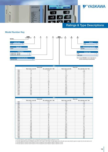
atings & type Descriptionsmodel number KeyCIMR- A4CA0004 F A AAC Drive<strong>A1000</strong><strong>Inverter</strong> <strong>Series</strong>A1stRevisionAEuropeRegion codeCEnvironmental SpecificationStandardAVoltage Class3-phase, 200 – 240 VAC 23-phase, 380 – 480 VAC 4IP00NEMA Type1Enclosure TypeAFCustomized SpecificationStandard modelANote: Contact YASKAWA for more information onenvironmental tolerance specifications.200 VNormal duty* 1Heavy dutyRated output current [AA]Max. applicable motor* 2 [kW] Rated output current [AA]Max. applicable motor* 2 [kW]0004 3.5 0.75 3.2* 3 0.40006 6 1.1 5* 3 0.750010 9.6 2.2 8* 3 1.50012 12 3 11* 3 2.20021 21 5.5 17.5* 3 4.00030 30 7.5 25* 3 5.50040 40 11 33* 3 7.50056 56 15 47* 3 110069 69 18.5 60* 3 150081 81 22 75* 3 18.50110 110 30 85* 3 220138 138 37 115* 3 300169 169 45 145* 4 370211 211 55 180* 4 450250 250 75 215* 4 550312 312 90 283* 4 750360 360 110 346* 4 900415 415 110 415* 1 110400 VNormal duty* 1Heavy dutyRated output current [AA]Max. applicable motor* 2 [kW] Rated output current [AA]Max. applicable motor* 2 [kW]0002 2.1 0.75 1.8* 3 0.40004 4.1 1.5 3.4* 3 0.750005 5.4 2.2 4.8* 3 1.50007 6,9 3 5.5* 3 2.20009 8.8 4.0 7.2* 3 30011 11.1 5.5 9.2* 3 4.00018 17.5 7.5 14.8* 3 5.50023 23 11 18* 3 7.50031 31 15 24* 3 110038 38 18.5 31* 3 150044 44 22 39* 3 18.50058 58 30 45* 3 220072 72 37 60* 3 300088 88 45 75* 5 370103 103 55 91* 3 450139 139 75 112* 4 550165 165 90 150* 4 750208 208 110 180* 4 900250 250 132 216* 4 1100296 296 160 260* 4 1320362 362 185 304* 4 1600414 414 220 370* 4 1850515 515 250 450* 1 2200675 675 355 605* 1 3150930 930 500 810* 1 4501200 1200 630 1090* 1 560*1: This value assumes a carrier frequency of 2 kHz. Increasing the carrier frequency requires a reduction in current.*2: The motor capacity (kW) refers to a YASKAWA 4-pole, 60 Hz, 200 V motor or 400 V motor. The rated output current of the drive output amps should be equal to or greater than the motor rated current.*3: This value assumes a maximum carrier frequency of 8 kHz. Increasing the carrier frequency requires a reduction in current.*4: This value assumes a maximum carrier frequency of 5 kHz. Increasing the carrier frequency requires a reduction in current.19