UNIFLOW-200 Instruction manual - Process Control Kft
UNIFLOW-200 Instruction manual - Process Control Kft
UNIFLOW-200 Instruction manual - Process Control Kft
- No tags were found...

Create successful ePaper yourself
Turn your PDF publications into a flip-book with our unique Google optimized e-Paper software.
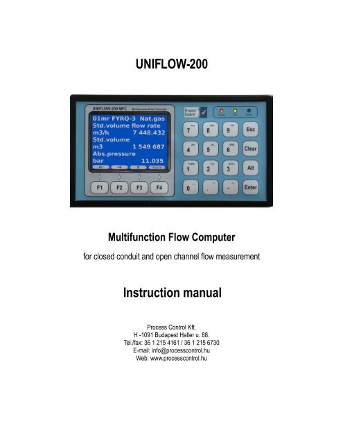
<strong>UNIFLOW</strong>-<strong>200</strong>Multifunction Flow Computerfor closed conduit and open channel flow measurement<strong>Instruction</strong> <strong>manual</strong><strong>Process</strong> <strong>Control</strong> <strong>Kft</strong>.H -1091 Budapest Haller u. 88.Tel./fax: 36 1 215 4161 / 36 1 215 6730E-mail: info@processcontrol.huWeb: www.processcontrol.hu
UNI<strong>200</strong>_<strong>Instruction</strong>_<strong>manual</strong>_EN <strong>200</strong>8.06.08Revision tracking sheetJun <strong>200</strong>8This <strong>manual</strong> may be revised periodically to incorporate new or updated information. Listed beloware the revision dates:RevisionDateInitial issue Jun <strong>200</strong>8While information in this <strong>Instruction</strong> Manual is presented in good faith and believed to be accurate,<strong>Process</strong> <strong>Control</strong> <strong>Kft</strong>. does not guarantee satisfactory results from reliance upon such information.Nothing contained herein is to be construed as a warranty or guarantee, express or implied,regarding the performance, merchantability, fitness or any other matter with respect to theproducts. <strong>Process</strong> <strong>Control</strong> <strong>Kft</strong>. reserves the right, without notice, to alter or improve the designs orspecifications of the products described herein.2
UNI<strong>200</strong>_<strong>Instruction</strong>_<strong>manual</strong>_EN <strong>200</strong>8.06.08Contents1 About this <strong>manual</strong> ........................................................................................................................... . 102 Introduction ....................................................................................................................................113 Technical specification ...................................................................................................................143.1 General features .....................................................................................................................143.2 Technical data ..........................................................................................................................143.3 Accessories ............................................................................................................................174 Plug-in boards and hardware operation ..........................................................................................184.1 Plug-in boards ......................................................................................................................... . 184.2 Hardware operation ................................................................................................................195 Installation, wiring and start-up ......................................................................................................215.1 Installation ............................................................................................................................. ...215.2 Wiring .....................................................................................................................................215.3 Start-up ..................................................................................................................... ...............235.4 Start and stop metering streams ............................................................................................246 Basic operation ..............................................................................................................................256.1 Keypad ...................................................................................................................................256.1.1 Numeric keys ..................................................................................................................256.1.2 Editing keys .....................................................................................................................266.1.3 Function keys ..................................................................................................................266.2 Display ..................................................................................................................... ................276.2.1 Navigating the display .....................................................................................................296.3 Security levels ......................................................................................................................... . 296.4 The menu system ...................................................................................................................306.5 Entering data ..........................................................................................................................356.5.1 Changing numeric data ...................................................................................................356.5.2 Changing selection .......................................................................................................... 366.6 Data pages .............................................................................................................................367 Maintenance and troubleshooting ..................................................................................................378 Support .......................................................................................................................................... 388.1 UNISetup ................................................................................................................................388.2 UNIArchive ............................................................................................................................ ... 388.3 VISION SCADA system ..........................................................................................................389 Detailed operation – The menu tree ..............................................................................................409.1 Flow .........................................................................................................................................409.1.1 Stream data ..................................................................................................................... 409.1.1.1 Summary display 1, 2, 3 and 4 ................................................................................409.1.1.2 Periodic totals ..........................................................................................................429.1.1.3 Flow rates ................................................................................................................439.1.1.4 Cumulative totals .....................................................................................................449.1.1.5 Premium totals .........................................................................................................459.1.1.6 Fault totals ...............................................................................................................469.1.1.7 <strong>Process</strong> data ............................................................................................................479.1.1.7.1 Flow meter data ...............................................................................................479.1.1.7.2 Fluid data ..........................................................................................................503
UNI<strong>200</strong>_<strong>Instruction</strong>_<strong>manual</strong>_EN <strong>200</strong>8.06.089.1.1.7.3 Gas composition ..............................................................................................529.1.2 Plant I/O ..........................................................................................................................529.1.3 Archive data ....................................................................................................................569.1.4 Modbus registers ............................................................................................................. 589.1.5 Data transfer ..................................................................................................................599.1.6 Extra summary display .................................................................................................... 609.2 Parameters .............................................................................................................................619.2.1 I/O signal setup ...............................................................................................................619.2.1.1 Analogue (4-20 mA) input channel ..........................................................................629.2.1.2 PRT/RTD input channel ...........................................................................................659.2.1.3 Pulse input channel .................................................................................................669.2.1.4 Digital input channel ................................................................................................749.2.1.5 Digital output channel ..............................................................................................769.2.1.6 Analogue (4-20 mA) output channel ........................................................................819.2.1.7 HART signal input channel ......................................................................................829.2.1.8 Modbus signal channel ............................................................................................859.2.2 Stream setup ...................................................................................................................879.2.2.1 Physical stream setup .............................................................................................879.2.2.1.1 Fluid selection ..................................................................................................889.2.2.1.1.1 Natural gas ...............................................................................................889.2.2.1.1.2 Liquids ....................................................................................................... 999.2.2.1.1.2.1 Crude oil and products ......................................................................999.2.2.1.1.2.2 Ethanol ............................................................................................1029.2.2.1.1.2.3 General liquid ..................................................................................1039.2.2.1.1.2.4 Liquid mixture ..................................................................................1059.2.2.1.2 Flow meter selection ......................................................................................1079.2.2.1.2.1 Orifice meter ...........................................................................................1079.2.2.1.2.2 Segmental orifice plate ...........................................................................1099.2.2.1.2.3 V-Cone meter ..........................................................................................1109.2.2.1.2.4 Annubar ...................................................................................................1119.2.2.1.2.5 Gas turbine meter, Liquid turbine meter, Vortex meter, Mass flow meter,Ultrasonic meter, Rotameter, Electromagnetic flow meter ........................................1129.2.2.1.2.6 Flow meter with power characteristic ......................................................1149.2.2.1.3 Stream setup ..................................................................................................1159.2.2.1.3.1 Stream setup – fluid: natural gas, flow meter: orifice meter ....................1169.2.2.1.3.2 Stream setup – fluid: natural gas, flow meter: ultrasonic meter ..............1219.2.2.1.3.3 Stream setup – fluid: crude oil, flow meter: liquid turbine meter .............1239.2.2.1.4 Premium limits ................................................................................................1299.2.2.2 Virtual stream setup ............................................................................................... 1309.2.2.2.1 Virtual stream setup .......................................................................................1309.2.2.2.2 Virtual stream Premium limits ........................................................................1339.2.2.3 Premium mode setup ............................................................................................1339.2.2.4 Fault mode setup ...................................................................................................1359.2.3 General data .................................................................................................................136........................................................................................................................ ..................1369.2.3.1 Date and time ........................................................................................................1364
UNI<strong>200</strong>_<strong>Instruction</strong>_<strong>manual</strong>_EN <strong>200</strong>8.06.089.2.3.2 Time periods ..........................................................................................................1379.2.3.3 User defined setup ................................................................................................1389.2.3.3.1 Archiving ......................................................................................................... 1389.2.3.3.2 Display ............................................................................................................1389.2.3.3.2.1 Summary display setup ..........................................................................1389.2.3.3.2.2 Extra summary display setup ..................................................................1439.2.3.3.3 Print ................................................................................................................1439.2.3.4 Averaging setup .....................................................................................................1449.2.3.5 Password setup .....................................................................................................1459.2.3.6 Reset .......................................................................................................................1469.2.3.6.1 Totals reset .....................................................................................................1469.2.3.6.2 General reset .................................................................................................1479.2.3.7 Version control ......................................................................................................1489.2.3.8 Company data ......................................................................................................1499.2.3.9 LCD settings ..........................................................................................................1509.2.4 Interfaces ........................................................................................................................1519.2.4.1 Serial ports ............................................................................................................. 1519.2.4.2 Ethernet port ..........................................................................................................1539.2.5 Operator parameters ..................................................................................................... 1549.2.5.1 Keypad & limits ......................................................................................................1549.2.5.2 Keypad values .......................................................................................................1559.3 Alarms and events system ...................................................................................................1579.3.1 I/O channel alarms ........................................................................................................1589.3.1.1 Analog input channel (4-20 mA) alarms ................................................................1589.3.1.2 PRT/RTD (Pt100) channel alarms ......................................................................... 1599.3.1.3 Pulse input channel (flow pulse signal) alarms ......................................................1599.3.1.4 Pulse input channel (flow frequency signal) alarms ...............................................1609.3.1.5 Pulse input channel (density frequency signal) alarms ..........................................1609.3.1.6 Analog output (4-20 mA) channel alarms ..............................................................1619.3.1.7 Pulse output channel alarms .................................................................................1619.3.1.8 Modbus (serial communication) channel alarms .................................................... 1619.3.2 Metering stream alarms ...............................................................................................1619.3.2.1 Calculation alarms .................................................................................................1619.3.3 Common alarm and status output ................................................................................. 1629.3.3.1 Common alarm ......................................................................................................1629.3.3.2 Status output .......................................................................................................... 1639.3.4 Alarm list .........................................................................................................................1639.3.5 Event list .........................................................................................................................1649.3.6 Download log ................................................................................................................1659.4 Tests ....................................................................................................................................... 1659.4.1 Tests – ANI4PT2 board .................................................................................................1669.4.2 Tests – ANI8 board ........................................................................................................1669.4.3 Tests – PT4 board .........................................................................................................1679.4.4 Tests – AODIO484 board ..............................................................................................1679.4.5 Tests – PDIO484 board ................................................................................................. 1689.5 Calibration ............................................................................................................................1695
UNI<strong>200</strong>_<strong>Instruction</strong>_<strong>manual</strong>_EN <strong>200</strong>8.06.089.6 Help ........................................................................................................................................1699.7 English/Magyar .....................................................................................................................16910 Communication ..........................................................................................................................17010.1 Serial link setup ..................................................................................................................17010.2 Ethernet link setup ..............................................................................................................17110.3 Communication device address .........................................................................................17110.4 Protocol implementation .....................................................................................................17210.4.1 Implemented Modbus command codes .....................................................................17210.4.1.1 Read multiply registers (code: 3) ......................................................................... 17210.4.1.2 Write multiply registers (code: 16) .......................................................................17210.4.2 Calculation of CRC check sum ...................................................................................17310.4.3 Data types in the Modbus registers ............................................................................17310.4.3.1 8 bit binary unsigned integer ...............................................................................17310.4.3.2 16 bit binary unsigned integer .............................................................................17310.4.3.3 32 bit binary signed integer .................................................................................17410.4.3.4 Floating point number ..........................................................................................17410.5 Standard Modbus register map (2 byte/register, Uniflow-100 compatible) .........................17510.5.1 Accessing periodic totals ............................................................................................. 18010.6 Daniel Modbus register map (4 byte/register) ....................................................................18210.6.1 Registers for system date and time modification via Modbus link ............................... 18210.6.2 Registers for totals ......................................................................................................18210.6.3 Registers for other measured data .............................................................................185Annex A. Reports ..........................................................................................................................187Annex B. Drawings .........................................................................................................................190Annex C. Application note for U<strong>200</strong>_HTI4x15 I/O board ..............................................................2026
UNI<strong>200</strong>_<strong>Instruction</strong>_<strong>manual</strong>_EN <strong>200</strong>8.06.08FiguresFigure 5-1 Backplane connectors.................................................................................. ........22Figure 6-2 Front panel............................................................................................... ............25Figure 6-3 Menu page.................................................................................. .........................28Figure 6-4 Data page.......................................................................................... ...................28Figure 6-5 Main menu page............................................................................. .....................30Figure 6-6 Main menu - Flow........................................................................... ....................31Figure 6-7 Main menu - Parameters...................................................................................... 34Figure 6-8 Main menu – Alarm and events, Tests, Calibration, Help.................................35Figure 7-9 Fuses.............................................................................................. ......................37Figure 8-10 Capabilities of <strong>UNIFLOW</strong>-<strong>200</strong>................................................................ ........39Figure 9-11 The default summary display...................................................... ......................41Figure 9-12 Periodic totals................................................................................. ...................42Figure 9-13 Flow rates.............................................................................. ............................43Figure 9-14 Cumulative totals........................................................................................ .......44Figure 9-15 Premium totals........................................................................................... ........45Figure 9-16 Fault totals................................................................................. ........................46Figure 9-17 <strong>Process</strong> data menu page.................................................................................. ...47Figure 9-18 Flow meter data for differential pressure devices (orifice, nozzle, Venturi tube)................................................................................................................................................ .48Figure 9-19 Flow meter data for pulse output flow meters (turbine meter, Vortex meter,etc.).............................................................................................................. ...........................48Figure 9-20 Flow meter data (Flowsic-600 US meter, serial communication)....................49Figure 9-21 Flow meter data (QSonic US meter, serial communication)............................49Figure 9-22 Fluid data for natural gas.............................................................................. .....50Figure 9-23 Fluid data for crude oil and refined products....................................................50Figure 9-24 Fluid data for ethanol............................................................. ...........................51Figure 9-25 Fluid data for general liquid................................................................. .............51Figure 9-26 Fluid data for liquid mixture....................................................... ......................51Figure 9-27 Gas composition data for natural gas..................................................... ...........52Figure 9-28 I/O board n data page for U<strong>200</strong>_ANI8 board..................................................53Figure 9-29 I/O board n data page for U<strong>200</strong>_ANI4PT2 board...........................................53Figure 9-30 I/O board n data page for U<strong>200</strong>_PDIO484 board............................................54Figure 9-31 I/O board n data page for U<strong>200</strong>_AODIO484 board........................................54Figure 9-32 Modbus signal data page.................................................................... ...............55Figure 9-33 Archive data data page........................................................... ...........................56Figure 9-34 Modbus registers data page................................................................. ..............58Figure 9-35 Data transfer data page........................................................................ ..............59Figure 9-36 Analogue (4-20 mA) input channel data page.................................................62Figure 9-37 Error curve data page for flow rate signal.......................................................63Figure 9-38 PRT/RTD input channel data page......................................................... ...........65Figure 9-39 Pulse input channel (signal type = flow pulse) data page................................67Figure 9-40 Error curve data page (signal type = flow pulse).............................................69Figure 9-41 Pulse input channel (signal type = flow check pulse) data page......................697
UNI<strong>200</strong>_<strong>Instruction</strong>_<strong>manual</strong>_EN <strong>200</strong>8.06.08Figure 9-42 Pulse input channel (signal type = flow frequency) data page.........................70Figure 9-43 Error curve data page (signal type = flow frequency).....................................72Figure 9-44 Pulse input channel (signal type = density frequency) data page.....................72Figure 9-45 Digital input channel (signal type = dual state) data page...............................74Figure 9-46 Digital input channel (signal type = pulse) data page.......................................75Figure 9-47 Digital output channel (signal type = pulse) data page....................................76Figure 9-48 Digital output channel (signal type = STR FR alarm) data page.....................77Figure 9-49 Digital output channel (signal type = Analog input alarm) data page..............78Figure 9-50 Digital output channel (signal type = Digital input alarm) data page..............79Figure 9-51 Digital output channel (signal type = Common alarm) data page....................80Figure 9-52 Digital output channel (signal type = Time base) data page............................80Figure 9-53 Analogue (4-20 mA) output channel data page...............................................81Figure 9-54 HART input channel data page................................................. ........................83Figure 9-55 Error curve data page for flow rate signal.......................................................84Figure 9-56 Modbus channel data page............................................................... .................86Figure 9-57 Stream selection data page.............................................................. ..................87Figure 9-58 Natural gas data page............................................................. ...........................88Figure 9-59 Natural gas detailed gas composition menu page............................................89Figure 9-60 Natural gas composition selection data page...................................................89Figure 9-61 Natural gas keypad composition data page................................................... ....90Figure 9-62 Natural gas Modbus registers data page..........................................................91Figure 9-63 Natural gas limited gas composition data page...............................................92Figure 9-64 Crude oil and product data page....................................................................... .99Figure 9-65 Ethanol data page................................................................... .........................102Figure 9-66 General liquid data page............................................................................. .....104Figure 9-67 Liquid mixture data page................................................................................ .105Figure 9-68 Orifice meter data page............................................................. ......................107Figure 9-69 Segmental orifice plate data page..................................................................109Figure 9-70 V-Cone meter data page................................................................................... 110Figure 9-71 Annubar data page................................................................... ........................111Figure 9-72 Gas turbine meter, Liquid turbine meter, Vortex meter, Mass flow meter,Ultrasonic meter, Rotameter, Electromagnetic flow meter data page.................................113Figure 9-73 Flow meter with power characteristic data page............................................114Figure 9-74 Stream setup data page, fluid: natural gas, flow meter: orifice meter............116Figure 9-75 Stream setup data page, fluid: natural gas, flow meter: ultrasonic meter......121Figure 9-76 Stream setup data page, fluid: crude oil, flow meter: liquid turbine..............124Figure 9-77 Premium limits data page...................................................................... ..........129Figure 9-78 Virtual stream selection data page................................................................. ..130Figure 9-79 Virtual stream setup data page........................................................................131Figure 9-80 Premium limits data page...................................................................... ..........133Figure 9-81 Premium mode setup data page....................................................................... 134Figure 9-82 Fault mode setup data page............................................................. ................135Figure 9-83 Date and time data page............................................................. .....................136Figure 9-84 Time periods data page.............................................................................. ......137Figure 9-85 Summary display setup data page....................................................... ............138Figure 9-86 Display editing data page, General display.....................................................1398
UNI<strong>200</strong>_<strong>Instruction</strong>_<strong>manual</strong>_EN <strong>200</strong>8.06.08Figure 9-87 Display editing data page, Previous month display.......................................141Figure 9-88 Display editing data page, Current month display.........................................142Figure 9-89 Extra summary display setup data page.................................................. ........143Figure 9-90 Averaging setup data page...................................................................... .........144Figure 9-91 Password setup data page..................................................................... ...........145Figure 9-92 Totals reset data page...................................................................................... .146Figure 9-93 General reset data page...................................................... .............................147Figure 9-94 Version control data page............................................................ ....................148Figure 9-95 User data data page........................................................................................ ..149Figure 9-96 LCD settings data page....................................................... ............................150Figure 9-97 Serial ports data page............................................................ ..........................151Figure 9-98 Ethernet port data page.............................................................................. ......153Figure 9-99 Operator data - limits data page.................................................. ....................154Figure 9-100 Keypad values data page................................................................. ..............155Figure 9-101 Tests – ANI4PT2 board data page............................................................. ....166Figure 9-102 Tests – ANI8 board data page.......................................................................167Figure 9-103 Tests – PT4 board data page...................................................................... ....167Figure 9-104 Tests – AODIO484 board data page............................................................168Figure 9-105 Tests – PDIO484 board data page...................................................... ...........169TablesTable 4-1 I/O board types.......................................................................................... ............18Table 4-2 Communication interfaces............................................................... .....................19Table 9-3 Natural gas properties modes......................................................................... .......98Table 9-4 Ranges of gas mixture characteristics for compression factor calculation fromdetailed gas composition.................................................................................... ....................98Table 9-5 Ranges of gas mixture characteristics for compression factor calculation fromlimited set of gas composition............................................................................................ ....98Table 9-6 Default values of the calorific value and CO2 emission factors........................101Table 9-7 Stream data for general summary display.........................................................139Table 9-8 Stream data for previous month summary display............................................140Table 9-9 Stream data for current month summary display..............................................140Table 10-10 Communication device addresses........................................................... ........1689
UNI<strong>200</strong>_<strong>Instruction</strong>_<strong>manual</strong>_EN <strong>200</strong>8.06.081 About this <strong>manual</strong>This <strong>manual</strong> introduces the <strong>UNIFLOW</strong>-<strong>200</strong> multifunction flow computer. It describes the installationprocedure and shows how to operate the system including entering and modifying data. Basicmaintenance and troubleshooting information is also provided.The information in this <strong>manual</strong> is arranged as follows:Section 2 – Introduction provides an overview of the <strong>UNIFLOW</strong>-<strong>200</strong> including the list of meteringstandards, fluids and flow meters available in the flow computer for configuration.Section 3 – Technical specification contains a complete list of physical, performance, andenvironmental specifications of the <strong>UNIFLOW</strong>-<strong>200</strong>.Section 4 – Plug-in boards and hardware operation provides the list of I/O boards available forselection together with their I/O channel capabilities. This section consists of the short descriptionof the hardware operation of the flow computer.Section 5 – Installation and wiring provides instruction on installing the <strong>UNIFLOW</strong>-<strong>200</strong>. Itdescribes the field wiring configurations.Section 6 – Basic operation shows how to use the <strong>UNIFLOW</strong>-<strong>200</strong>. This includes keypadfunctions, screen displays, system initialization, display navigation, data entry, and printing reports.Section 7 – Maintenance and troubleshooting provides maintenance and troubleshootinginformation, including the basic board-level test procedures.Section 8 – Support describes the software tools provide for the convenience of operation of the<strong>UNIFLOW</strong>-<strong>200</strong>.Section 9 – Detailed operation – The menu tree describes in depth the menu structure of the<strong>UNIFLOW</strong>-<strong>200</strong>. It guides through the steps required to setup the <strong>UNIFLOW</strong>-<strong>200</strong> for a particularflow measurement task. It gives the full list of options available for selection in the setupprocedure.Section 10 – Alarms and events describes the full list of alarms and events that may appear inthe alarm and event files.Section 11 – Communication describes the communication capabilities of the <strong>UNIFLOW</strong>-<strong>200</strong>.Annex A – Reports gives examples of the periodic reports available in the <strong>UNIFLOW</strong>-<strong>200</strong> foruploading and printing.Annex B – Drawings includes the drawings.Annex C – Application note for U<strong>200</strong>_HTI4x15 I/O board10
UNI<strong>200</strong>_<strong>Instruction</strong>_<strong>manual</strong>_EN <strong>200</strong>8.06.082 Introduction<strong>UNIFLOW</strong>-<strong>200</strong> multifunction flow computer is designed to measure flow of fluids flowing in closedconduits (gas, liquid, water and steam) and open channel (water). The flow computer performs thedata processing and displaying function in the flow metering system. The flow computer calculatesthe uncorrected and corrected volume, mass and energy flow rate of the fluid. It totalizes theuncorrected and corrected volume, mass and energy for the accounting periods.<strong>UNIFLOW</strong>-<strong>200</strong> MFC represents the fourth generation of flow computers incorporating more than 20years of experience in development and manufacturing at <strong>Process</strong> <strong>Control</strong> Ltd.The flow computer was designed to provide cost effective solution for multi stream applications.Benefits of the flow computer allowing remarkable cost reduction comparing to the single streamflow computers: sharing of the transmitters between metering streams is possible; PRT sensors can be connected directly to the flow computer; no temperature transmitteris required; power supply output for transmitters is provided; no separate power supply unitsrequired; additional I/O modules expand the metering capability of the flow computer withmoderated additional cost only; flexible communication capabilities allows easy system integration.The manufacturer <strong>Process</strong> <strong>Control</strong> Ltd provides support for the end users to integrate the flowcomputer into metering systems and into data acquisition and process visualization systems. Themanufacturer also can provide complete solution for flow metering task, including the design,manufacturing and implementation if required.Flow meters that can be selected in the flow computer and the standards related pressure differential devices; orifice plate, nozzle, Venturi tube (ISO 5167, edition 1991, 1998 or <strong>200</strong>3) V-Cone meter (according to manufacturer’s method); Annubar (according to manufacturer’s method); segmental orifice plate;flow meters with linear output signal; turbine meter; Vortex meter; electromagnetic flow meter; ultrasonic flow meter; mass flow meter.flow meters with nonlinear output signal; rotameter; flow meter with power characteristic.11
UNI<strong>200</strong>_<strong>Instruction</strong>_<strong>manual</strong>_EN <strong>200</strong>8.06.08Fluids that can be selected in the flow computer together with fluid properties calculation hydrocarbon gas mixtures (natural gas, coke oven gas, blast furnace gas); pure gases (air, nitrogen, oxygen, argon, carbon-monoxide, ethylene, ammonia,propane, general gas) steam and hot water as energy supply fluids; liquids (crude oil, refined products, ethanol, general liquid);Standards and procedures for fluid properties calculation hydrocarbon mixtures compression factoro AGA8 (edition 1985 and 1992) detailed and gross methods;o GERG 91;o AGA NX19;o GOST 30319. calorific values, relative density and base densityo ISO 6976 (edition 1995). dynamic viscosity and isentropic exponento GOST 30319 gas compositiono read on-line from a gas chromatograph,o downloaded from a supervisory system,o fixed value.pure gases compression factor, dynamic viscosity and isentropic exponento HE-64 (calculation procedure of Hungarian Office of Measure);crude oil and refined products temperature volume correction factorso ASTM D1250/API 2540 Tables 54A, 54B, 54C pressure volume correction factorso API MPMS Chapter 11.2.1M and 11.2.2Msteam and water physical propertieso Industrial Formulation 1997 for the Thermodynamic Properties of Water andSteam (IAPWS-IF97)ethanol physical propertieso Council Directive 76/766/EECo Horst Bettin, Frank Spieweck: A Revised Formula for the Calculation ofAlcoholometric Tables. PTB-Mitteilungen 100 6/9012
UNI<strong>200</strong>_<strong>Instruction</strong>_<strong>manual</strong>_EN <strong>200</strong>8.06.08<strong>UNIFLOW</strong>-<strong>200</strong> is a Gas-volume electronic conversion device complying with EN 12405.The <strong>UNIFLOW</strong>-<strong>200</strong> MFC calculates the CO2 emission for gaseous and liquid fuels according to<strong>200</strong>4/156/EK and IPCC 1996.<strong>UNIFLOW</strong>-<strong>200</strong> is capable to provide flow computer function for maximum of 8 metering streams.In other words: in one <strong>UNIFLOW</strong>-<strong>200</strong> we have 8 independent flow computers.In general each metering stream has the input signals as follows: flow meter signal signals for correction (pressure, temperature, density, gas composition, etc.)Depending on the application one single signal for correction can be assigned to several meteringstreams. If here is no transmitter for a particular signal for correction the flow computer will use afixed value for that signal.In case of signal failure the flow computer revert to the fixed value of that signal and this value willbe used in the flow calculation.Beside the 8 physical metering streams the flow computer is capable to provide 4 virtual meteringstreams. The virtual metering streams are to produce data from the flow rates of the physicalmetering streams. The virtual streams can be configured to give sum, difference, product or ratio(or their combination) of the physical streams. It can be used to setup a simple energy balance fora small group of consumers.For more complex energy systems <strong>Process</strong> <strong>Control</strong> Ltd can provide a PC based software packageto implement energy balance with data processing, process visualization, trend and archiving asrequested.The accuracy of the flow measurement is a key issue. <strong>UNIFLOW</strong>-<strong>200</strong> high precision inputs, theimplementation of the latest editions of the flow metering standards provide minimum contributionof the flow computer in the uncertainty budget of the metering system.Utilization of the digital communication with the flow meters and transmitters can further reduce theoverall uncertainty of the measurement.13
UNI<strong>200</strong>_<strong>Instruction</strong>_<strong>manual</strong>_EN <strong>200</strong>8.06.083 Technical specification3.1 General featureshigh capacity 32-bits microprocessormodular design, up to 5 I/O boardsup to 8 physical metering streamsup to 4 virtual metering streamsflow meters: orifice plate, nozzle, Venturi tube, segmental orifice plate, Annubar, V-Conemeter, turbine meter, Vortex meter, ultrasonic meter, electromagnetic meter, mass flowmeter, rotameter, meter with power characteristicfluids: gas, liquid and water steammode of operation: metering mode, configuration mode, test modeconfiguration: from keypad, via serial link, via ethernet linkpassword protected parameters, audit trial logparameters and totals integrity protection: non volatile memoryarchiving: hourly, shift, daily, multi-day and monthly totals and averages for 400 daysoperator interface: alphanumerical and graphical displayRS232, RS485, RS422 serial links, 10/100 Ethernet and USB interfacestream independent signal processinghigh reliability, no battery, no potentiometerssupport: UNISetup configuration software, UNIArchive remote archive uploder software3.2 Technical dataAnalog inputs symmetrical inputs with galvanic isolation input range 0-20 mA/4-20 mA (operator selectable) accuracy +/- 0,02 % input impedance 100 ohm Potential diff. among inputs 50 V max.PRT/RTD inputs sensor type 100 ohms PRT standard or individually calibrated(other type on request) connection 4-wire accuracy +/- 0,1 o C maximum loop resistance 500 ohmsPulse/frequency inputs (NAMUR) frequency range 0…10000 Hz input signal level 2 V…10 V signal form square, unipolar signal counting without loss of pulses14
UNI<strong>200</strong>_<strong>Instruction</strong>_<strong>manual</strong>_EN <strong>200</strong>8.06.08 Uncertainty of frequency measurement 0.001 % max.Digital inputs potential-free contacts, open collector inputs (transistor) or 24 VDC inputs accepted andused as: static inputs, or pulse inputs (frequency: 50 Hz max., 50 % fill in ratio) internal power supply for potential-free inputs: 15 VDC, 6,8 kohmAnalog outputs output channels with individual galvanic isolation current range 0-20 mA / 4-20 mA (operator selectable) resolution 12 bits load 500 ohm max.Digital outputs galvanically isolated open collector (transistor), overvoltage- and overcurrent-protectedoutputs load 100 mA, 40 Vdc max.Digital communication serial links mode RS232/RS485/RS422 (operator selectable) baud rate 1<strong>200</strong>…38400 baud (operator selectable) protocol Modbus ASCII and RTU maximum cable length RS232 15 mRS485/RS4222 1<strong>200</strong> m 10/100 Ehernet protocol: Modbus TCP USB USB 1.1 port with standard-A receptacleHot/stand-by interface flow computer status output (to stand-by unit)change-over voltage-free contact, maximum load: 100 V, 100 mA operating closed contact (NO) fault opened contact (NC) flow computer status input (from hot unit)potential-free contact, open collector inputs (transistor) or 24 VDC input sense sensing inputKeyboard foil protected membrane keyboardDisplay3,5” QVGA (320 x 240) backlit TFT color LCD15
UNI<strong>200</strong>_<strong>Instruction</strong>_<strong>manual</strong>_EN <strong>200</strong>8.06.08Accuracy of the calculated data on the pulse and analog outputs and on the communicationinterface +/- 0.05 % under reference conditions +/- 0.1 % in the 0…50 °C ambient temperature rangeOperating conditions operating temperature -10…+50 o C operating humidity 0…90 % non-condensing climatic class normal EMC complies with EU EMC regulation storage temperature -25…+70 o CPower requirements power supply 230 VAC +10 %/-15 %, 50 Hz +/-3 Hz24 VDC nominal, 20 VDC … 35 VDC power consumption 25 VA max.Case and mountingPanel mounted version front panel 196 mm W x 110 mm H case depth 272 mm minimum cabinet depth 320 mm panel cutout 186 mm W x 91 mm H weight 4.3 kg protection IP20prepared for sealingplug-in connectorso 230 V power supply IEC60320 C14 chassis plugo 24 VDC plug-in screw terminalo input/output signals 25-pin DSUB connector (female)o serial links 9-pin DSUB connector (male)o 10/100 ethernet RJ45 UTPo USB host and device Standard-A receptacleo flow computer status plug-in screw terminalStand alone version size 230 mm W x 270 mm H x 160 mm D protection IP65 prepared for sealingProtection against electrical shockClass ICertificates MKEH (OMH) EC-type examination certificate TH-8430 MEEI EMC conformance certificate M5 2692542 0116
UNI<strong>200</strong>_<strong>Instruction</strong>_<strong>manual</strong>_EN <strong>200</strong>8.06.083.3 AccessoriesList of accessories supplied with <strong>UNIFLOW</strong>-<strong>200</strong>25-pin DSUB connector (male) 1 .. 5*9-pin DSUB connector (female) 1 .. 3**230 V power cord (2 meters) 1Fastener for mounting 4Fastener screw 4Fuse1 set<strong>Instruction</strong> <strong>manual</strong> 1* Depends on the number of boards fitted** Depends on the number of serial links fitted17
UNI<strong>200</strong>_<strong>Instruction</strong>_<strong>manual</strong>_EN <strong>200</strong>8.06.084 Plug-in boards and hardware operationThe modular design of the flow computer allows flexible combination of the I/O board to suitdifferent applications.The flow computer consists of the modules as listed below: mother board part of the base unit front panel with keypad and display part of the base unit power supply unit part of the base unit CPU board part of the base unit I/O boards application dependant serial extension module application dependantThe maximum number of I/O boards that can be installed is five. The maximum number ofmetering streams (8) can be defined only if the total number of input and output channels iscovered by the properly selected five I/O boards. Otherwise more then one <strong>UNIFLOW</strong>-<strong>200</strong> shouldbe installed.The base unit provides communication interfaces as listed below: serial link (RS232/RS485/RS422) 1 USB host 1 10/100 Ethernet 14.1 Plug-in boardsThe available I/O boards listed in the table below:I/O board name Number of SignalRemarkchannelsU<strong>200</strong>_ANI8 8 4-20 (0-20) mA current input selectable1 24 VDC/<strong>200</strong> mA transmitter powerU<strong>200</strong>_ANI4PT2 424-20 (0-20) mA current inputPRT/RTD inputselectable4-wire connection1 24 VDC/<strong>200</strong> mA transmitter powerU<strong>200</strong>_PT4 4 PRT/RTD input 4-wire connectionU<strong>200</strong>_PDIO484 484pulse/frequency inputdigital (contact) inputdigital (open collector) output static or pulseU<strong>200</strong>_AODIO484 4844-20 (0-20) mA current inputdigital (contact) inputdigital (open collector) outputU<strong>200</strong>_DE4 4 DE protocol input for single function(SF) or multi function (MF) transmitterwith 24 VDC transmitter power supplyU<strong>200</strong>_HTI4x15 60 HART communication input inmultidrop or broadcast mode4 independent loops, 15 PV per loopshigh level (active or passive)active or passive, stat. or pulseselectableactive or passive, stat. or pulsestatic or pulse2 off MF and 1 off SFor4 off SF transmitterThe loops are isolated ifexternal power supply is used18
UNI<strong>200</strong>_<strong>Instruction</strong>_<strong>manual</strong>_EN <strong>200</strong>8.06.08Table 4-1 I/O board typesThe available communication interfaces listed in the table below:Communication TypeRemarkmoduleCom1 port universal serial port part of the base unit on the CPUboardRS232/RS485/RS422 – selectableU<strong>200</strong>_SEmoduleserial extension moduleadditional com2 and com3 portsRS232/RS485/RS422 – selectable10/100 port 10/100 baseT Ethernet interface part of the base unit on the CPUboardUSP port USB 1.1 host part of the base unit on the CPUboardTable 4-2 Communication interfaces4.2 Hardware operationThe flow computer is built on the basis of the ATMEL ATM9<strong>200</strong>…ARM microprocessor.The application software of the flow computer runs under the UX<strong>200</strong> operating system.The operating system and the application software are stored in the compact flash memory(PCMCIA device). The boot program is stored in data flash memory. The calculation data aresaved periodically into I 2 C flash.All the parameters, calculation data and archive data are stored in flash memory so that the dataare retained in case of power failure.The working memory of the flow computer is 32 MB SDRAM.The real time clock chip (DALLAS DS12887) provides the time and date for the operation.It provides also 500 ms interrupts for the processor to synchronize the calculation cycles. Theclock chip has its own built-in lithium battery providing independent operation from the externalpower.The human – machine interface of the flow computer is the 320x240 dots backlit color LCD and thefoil protected membrane keyboard.There are three LEDs on the front panel.The POWER LED indicates the presence of power supply.The RUN LED indicates the normal operation of the flow computer.The ALARM LED indicates the alarm status.The Com1, Com2, Com3 serial ports provide asynchrony communication links to other devices. Allof them can be configured as RS23 or RS485 or RS422 port. The parameters of the ports areoperator selectable.19
UNI<strong>200</strong>_<strong>Instruction</strong>_<strong>manual</strong>_EN <strong>200</strong>8.06.08The 10/100 BaseT Ethernet port allows to connect the flow computer to the LAN or WAN. Theparameters of the Ethernet port (IP address, subnet mask, default gateway) are operatorselectable. The Ethernet port can be configured to provide DHCP function.The USB port is provided for easy transfer of the archive data files to pen drive.The flow computer can accommodate up to five I/O boards for field signal connection. It isrecommended to install the I/O boards in the numbered slots starting from one. The type of the I/Oboards is recognized automatically by the CPU board.The status of the flow computer (normal operation or in error) is signaled with a dual state doublepole voltage free contact. The state of the contact and the state of the RUN LED are synchronized.See details in the section 9.3.3The power supply unit provides two independent groups of voltages for the flow computeroperation. The voltages are isolated by DC/DC converters for high noise immunity. The voltagesare: TTL level voltageoo+5 V (Vcc) to supply the digital circuitsprediction of power failure to provide- smooth program stopping and- finishing the data saving processvoltage for analogue circuitso +24 V for transmitter power supplyo +/-15 V to supply the analogue circuitsThe I/O boards include also DC/DC converters to isolate the field input signals and thecommunication interfaces from the internal circuits.The flow computer can be powered from: 230 V 50 Hz or 24 V DCpower source. Both power sources can be connected simultaneously. If power exists on bothpower inputs then the flow computer takes power from the 230 V 50 Hz inputs. If the power fails onthis input then the flow computer automatically switch to the 24 VDC power input. The powerswitch over will not affect the operation of the flow computer.To assure high reliability and low maintenance no potentiometers and no batteries are installed inthe flow computer.20
UNI<strong>200</strong>_<strong>Instruction</strong>_<strong>manual</strong>_EN <strong>200</strong>8.06.085 Installation, wiring and start-up<strong>UNIFLOW</strong>-<strong>200</strong> flow computer is designed for panel mounting. Its outer case is made of paintedwelded steel list to provide magnetic screening.The mechanical structure of the flow computer is constructed in such a way that after loosing thetwo fixing screws on the back side of the unit the complete internal can be pulled out from the front.The terminals and the sockets for the signal connections and the fuse holders are located on thebackplane of the unit.The base unit consists of 4 PCBs, the mother board, the front panel, the power supply and theCPU. The front panel connects to the mother board with flat ribbon cable. The CPU board and thepower supply are connected to the mother board with multi-pin sockets. There are 5 off 64-pinsockets on the mother board to accommodate the I/O boards for field signals. The field signals areconnected to the 25-pin DSUB sockets located at the rear edge of the I/O boards.5.1 InstallationInstallation of the <strong>UNIFLOW</strong>-<strong>200</strong> must conform to all applicable local codes and regulations. Allinstallation procedures should be in accordance with normal practices of good workmanship.The <strong>UNIFLOW</strong>-<strong>200</strong> panel mount is designed for use within the control room and should be placedin a position that provides ease of use, comfort, and safety for operators and maintenancepersonnel. The optimum height for viewing and using the display and keypad is at operator eyelevel.CAUTIONWhere one or more units are installed in a confined space or with other heat producing equipment,special attention should be given to the combined heating effect. This combined heat couldincrease the environmental temperature beyond its acceptable threshold impacting performance.Prepare the requested cut out in the panel for mounting. Refer to the drawing in the Annex B.Panel thickness should be at least 3 mm to prevent distortion.Carefully slide the <strong>UNIFLOW</strong>-<strong>200</strong> into the cut out. Secure the unit in the panel by means of thefour fastener supplied with the unit.5.2 WiringAll local wiring practices and regulations should be observed performing the wiring.The connectors and terminals accepting external wirings are located on the backplane of the flowcomputer as shown on the figure below.21
UNI<strong>200</strong>_<strong>Instruction</strong>_<strong>manual</strong>_EN <strong>200</strong>8.06.08USB Type BUSB Type ASerial port COM210/100 BaseT Ethernet Power 230 v 50 HzI/O board No.1I/O board No.2Power 24 VDCSense inputI/O board No.3I/O board No.4I/O board No.5Serial port COM1Status outputSerial port COM3Figure 5-1 Backplane connectorsPower supplyTwo different power supply inputs are available on the <strong>UNIFLOW</strong>-<strong>200</strong>. Both power supply inputcan be connected at the same time.230 V 50 Hz power supply is connected via IEC60320 C14 chassis plug.CAUTION<strong>UNIFLOW</strong>-<strong>200</strong> shall be connected to the power supply system with protective ground.24 VDC power supply connection is made by a plug-in screw terminal. The terminal is labeled24 V BAT.Serial portsThree communication ports are provided on the backplane of the flow computer.The ports use 9-pin DSUB male connectors and are labeled COM1, COM2 and COM3.The pin assignments of the connectors in case of RS232/RS485/RS422 configuration see in theAppendix B.22
UNI<strong>200</strong>_<strong>Instruction</strong>_<strong>manual</strong>_EN <strong>200</strong>8.06.08Ethernet portThis port is for high-speed communications using Ethernet local area network architecture.The speed of data transfer is 10/100 Mb/sec using a 10baseT twisted pair. The port uses an RJ45connector.USB portUSB port is for file transfer from the flow computer to pen drive device. The port uses a standard-Areceptacle.Status output and Sense inputA single pole, double throw relay with Normally Open or Normally Closed terminals provides thestatus (operating and error) of the flow computer. A flow computer failure causes the relay to deenergize.Connection is made by plug-in screw terminals.Contact is rated at 100 mA, 100 volts and is a Form “C” contact.The terminals are marked:O operatingC commonE faultThe Sense input accepts potential-free contact, open collector inputs (transistor) or 24 VDC inputfrom other flow computer working in pair in hot/stand-by mode.The terminals are marked:+S + signalS- - signalI/O board connectorsThe backplane has one 25-pin female D-type connectors for field wiring for each I/O board.See the pin assignment of the connector for each type of the boards in the Annex B5.3 Start-upAfter the <strong>UNIFLOW</strong>-<strong>200</strong> has been wired for power and external devices, it may be activated byenergizing the external power supply. When power is applied, the unit displays themessage Load in progress… Please be patient.After about 1 minute the operating system of the unit starts testing the internal parameters anddisplays messages indicating whether the parameters pass or fail the test. If some of theparameters are missed or damaged the default parameters are activated.After the tests the blinking message Restarted! appears on the display together with the date andtime of the restart and with the current date and time.There is also a message informing operator if the test of parameters was successful or the testfailed and default parameters were activated.After pressing any key the main menu appears on the display.If after the start-up the unit displays messages Parameters are damaged! and Checkparameters! then it is necessary to enter the Parameters menu and set the parameters required23
UNI<strong>200</strong>_<strong>Instruction</strong>_<strong>manual</strong>_EN <strong>200</strong>8.06.08for the particular application. Before setting up the proper parameters the unit will not start thenormal operation, i.e. will not start to perform the measurement.See the setup procedure in the Section 9.If after the start-up the unit displays messages Parameters are OK! then it starts the normaloperation, i.e. it will perform the measurement even if the blinking message Restarted! is seen onthe display.CAUTIONIf the operating conditions and the parameters of the application were not provided to themanufacturer then <strong>UNIFLOW</strong>-<strong>200</strong> is supplied from the factory with all the input and outputchannels inactive and all the metering streams are disabled.It is part of the start-up procedure to setup the unit for the particular application. See the setupprocedure in the Section 9.5.4 Start and stop metering streamsOnce the metering stream is properly configured it starts the flow calculation and never stops.When operator modifies any parameter and leaves the Parameters menu the flow calculation isinterrupted for few calculation periods while the new parameters are checked.The metering stream operation can be suspended if in the parameter setup the fluid or the flowmeter set to None (see section 9).24
UNI<strong>200</strong>_<strong>Instruction</strong>_<strong>manual</strong>_EN <strong>200</strong>8.06.086 Basic operationThe operation of the <strong>UNIFLOW</strong>-<strong>200</strong> is through an operator interface comprising an LCD displayand a keypad. The layout of the front panel is shown in figure below.6.1 KeypadFigure 6-2 Front panelThere are 20 keys located on the keypad grouped into 3 functional groups.6.1.1 Numeric keysThe numeric keys offer the full number set (0 - 9), decimal point (.), and a minus (-) key.They used to enter or change data.Each numeric key has secondary characters assigned to them.They are as follows:Numeric 1 to 8 – alphabetic letters from A to ZNumeric 0 – space ( )Numeric 7 – Exponent (Exp)Decimal point (.) – opening (() and closing ()) bracketMinus sign (-) – plus (+), multiply (*) and divide (/) signThe secondary characters activated by repeated key press.For example pressing the key 9 repeatedly the characters in the input field appears in the followingorder: 9 D E F É d e f é. Both uppercase and lowercase letters can be entered this way.Letters and special characters are used to- enter text information (e.g. the name of the metering stream)- enter equation in virtual stream definition (see Section 9.)25
UNI<strong>200</strong>_<strong>Instruction</strong>_<strong>manual</strong>_EN <strong>200</strong>8.06.08Exponent key is used to enter quantities in scientific notation. The exponent field is activated bypressing Alt key then Exp key. Letter “e” appears in the input field indicating that the exponent partof the number to be entered.Exponent key available only for the parameters which value in decimal notation exceeds the spaceavailable in the input fields.6.1.2 Editing keysEsc keyClear keyAlt keyEnter keypressing Esc key while editing any data entry field causes the editing stopped, theentered numbers or the selection mode is ignored and the original value of the field isrestored;pressing Esc key while data page is displayed (and no any data entry field is beingedited) causes exit from data page to the parent menu. All the modifications done afterthe last pressing of the Save key will be ignored and the original values of the data fieldswill be restored.pressing Clear key while editing any data entry field causes the last character entered iscleared.Alt key is used in conjunction with the Exp key to enter number in exponential format.Enter key is used to finish the data entry and data selection in the data entry fields.Pressing Enter do not causes the entered data is activated. To activate the data theSave key shall be pressed and the Parameters menu item shall be left. Exiting fromparameter menu the flow computer shows message Parameter update in progress. Themodified parameters will be used in flow calculation after the message disappears.6.1.3 Function keysThere are four function keys located below the display and marked with F1, F2, F3 and F4.The function keys have no one single particular function. They are multifunctional keys. The validfunctions of the keys at each particular display page are indicated in the bottom line of the display.The function keys are to navigate in the menu tree and select parameters or data items to view,change or save.The functions of the keys are as follows:left arrow move to the previous (upper) level of menu tree or return to the parent menu from thedata pageright arrow move to the next (lower) level of menu tree enter into data page if there is no more menu tree level26
UNI<strong>200</strong>_<strong>Instruction</strong>_<strong>manual</strong>_EN <strong>200</strong>8.06.08up arrow move by one item up in the menu list (on the menu page) or data list (on data page)down arrow move by one item down in the menu list (on the menu page) or data list (on data page)up-down arrow scroll through the menu items or data pages. After the last menu item or data page thefirst one appears.left-right arrow move to the next data entry field. After the last field the cursor jumps to the first field.Savesave the data on the data page displayed and return to the parent menuChangeMenuin the numeric entry field: clears the content of the field and enters the field for editingin the selection entry field: pressing Change key repeatedly the option list for theselection scrolls in the selection field. Press Enter when the desired option is displayedto make your selection.leaves the data page and return to the parent menuOKconfirm the selection of the highlighted item6.2 DisplayThe 320 x 240 dots backlit TFT color LCD display offers 14 lines of information displayed asalphanumeric and graphical characters.There are two different types of display pages available in the <strong>UNIFLOW</strong>-<strong>200</strong>: menu pageThe left pane of the menu page shows the menu tree levels the operator went through toarrive to the current position.The right pane shows the available menu items for selection. Press and key tohighlight the desired menu item. Press key to enter the next menu level or to datapage. Press to return the previous menu level.The figure below shows an example of the menu page27
UNI<strong>200</strong>_<strong>Instruction</strong>_<strong>manual</strong>_EN <strong>200</strong>8.06.08Figure 6-3 Menu pagedata pageThe data page is a list of parameters. The description, the value and the unit ofmeasurement of the parameters are shown.Press and key to highlight the desired data item.Press Change key to start editing the numeric entry field.Press Change key repeatedly to scroll through the available options of the selectionentry field.Press OK key to confirm the numeric value entered or the selection highlighted.Press Save key to save the new value of the parameter and return to the parent menu.Press Esc key if you want to discard the editing you have done and return to the parentmenu.The figure below shows an example of the data page.Figure 6-4 Data page28
UNI<strong>200</strong>_<strong>Instruction</strong>_<strong>manual</strong>_EN <strong>200</strong>8.06.08NOTEEach page consists of 15 lines.First line shows the stream identifier string.Last line shows the function pictogram of the F1 - F4 function keys.13 data lines can be seen on the screen. If more then 13 data items to be displayedscroll through the data lines with and keys.6.2.1 Navigating the displayFrom the main menu select the item you require by pressing and keys. Press key to enterthe next menu level. Select the required sub-menu item by pressing and keys and press key to enter the next sub-menu level. Repeating this procedure you arrive to the required datapage. Navigating in the menu tree you can see the menu and sub-menu items passed on the leftpane of the display.Pressing key returns to the previous menu level.6.3 Security levelsData are protected with password in the flow computer.There are three security levels. Each of them has its own password. Depending on the securitylevel the operator logged in he/she has the right to modify different groups of parameters.At Engineer level both the Operator and Engineer password can be modified.CAUTIONThe flow computer shipped with empty password list. It means that pressing Enter when the flowcomputer requires password you log in at Engineering level allowing modification all theparameters.Set your own Operator and Engineering level password to protect the parameters againstundesired modification. The procedure for password setting is described in Section 9.Remember the password you entered. If you forget your password you will have to ask theassistance of the manufacturer or you have to return the unit to the manufacturer.Guest levelAt Guest level all the parameters can be reviewed at the display but no any modification is allowed.The default password for Guest level is the Enter key. When the flow computer prompt for thepassword just press Enter key without entering any codes.The Guest level password can not be altered.Operator levelAt Operator level only the parameters listed in the Operator parameters submenu are available formodification. These parameters include the transmitter ranges, the high and low alarm limits andthe keypad values.The default password for the Operator level is Enter (no password is set).Engineer levelAt Engineer level all the parameters are available for editing.The default password for the Engineer level is Enter (no password is set).29
UNI<strong>200</strong>_<strong>Instruction</strong>_<strong>manual</strong>_EN <strong>200</strong>8.06.08IMPORTANTOnce the operator logged in at Operator or Engineer level and the inactivity period (i.e. noany key is pressed) exceeds 2 minutes the flow computer automatically logs out theoperator. This is to prevent accidental leaving the flow computer in the state where theparameters can be altered.6.4 The menu systemThe main menu consists of items as shown below.Figure 6-5 Main menu pageThe menu items Flow, Alarms & events, Help and language selection (Magyar/English) areaccessible without password.In Flow menu the metering data are shown grouped into different submenus.In Alarms & events menu the list of unacknowledged and acknowledged alarms can be seen. Thealarm log, event log and the downloaded gas composition log are accessible here also.The menu items Parameters and Tests require password to enter for accessing.The menu item Calibration is reserved for the manufacturer and for the authority calibrating the flowcomputer. It is accessible with special password only.The menu item Magyar (displayed if the current display language is English) / English (displayed ifthe current display language is Hungarian) is to change the language of the display.30
UNI<strong>200</strong>_<strong>Instruction</strong>_<strong>manual</strong>_EN <strong>200</strong>8.06.08The menu structure (the menu tree) shown on the figures below.Main menu Submenu 1 Submenu 2 Submenu 3 Submenu 4Flow Streams Summary display 1 data page (1.1.1)Periodic totals data page (1.1.2)Flowrates data page (1.1.3)Cumulative totals data page (1.1.4)Premium totals data page (1.1.5)Fault totals data page (1.1.6)<strong>Process</strong> data Flow meter data data page (1.1.7.1)Fluid data data page (1.1.7.2)(*)Summary display 2 data page (1.1.8)Summary display 3 data page (1.1.9)Summary display 4 data page (1.1.10)Plant I/O I/O board 1 data page (1.2.1)I/O board 2 data page (1.2.2)I/O board 3 data page (1.2.3)I/O board 4 data page (1.2.4)I/O board 5 data page (1.2.5)Modbus signals data page (1.2.6)Archive data data page (1.3)Modbus regs data page (1.4)Data transfer data page (1.5)Extra sum. display Extra sum. disp. 1 data page (1.6.1)Extra sum. disp. 2 data page (1.6.2)Extra sum. large. 1 data page (1.6.3)Extra sum. large 2 data page (1.6.4)(*) Depending on the selected flow meter and the fluid more data pages may exist.Figure 6-6 Main menu - Flow31
UNI<strong>200</strong>_<strong>Instruction</strong>_<strong>manual</strong>_EN <strong>200</strong>8.06.08Main menu - ParametersMain menu Submenu 1 Submenu 2 Submenu 3 Submenu 4 Submenu 5 Submenu 6 Submenu 7Parameters IO signals IO board 1 1. channel data page (2.1.1.1)2. channel data page (2.1.1.2)(*)n. channe data page (2.1.1.n)IO board 2 1. channel data page2. channel data page(*)n. channe data pageIO board 3 1. channel data page2. channel data page(*)n. channe data pageIO board 4 1. channel data page2. channel data page(*)n. channe data pageIO board 5 1. channel data page2. channel data page(*)n. channe data pageModbus signal 1. channel data page2. channel data page(*)n. channe data page32
UNI<strong>200</strong>_<strong>Instruction</strong>_<strong>manual</strong>_EN <strong>200</strong>8.06.08(Main menu - Parameters continued)Main menu Submenu 1 Submenu 2 Submenu 3 Submenu 4 Submenu 5 Submenu 6 Submenu 7Streams Physical stream Stream 1. Fluid Hydrocarb mixt. Natural gas data page (2.2.1.n.1.1.1)Coke oven gas data page (2.2.1.n.1.1.2)Blast furnace gas data page (2.2.1.n.1.1.3)Pure gases data page (2.2.1.n.1.2)Steamdata page (2.2.1.n.1.3)Waterdata page (2.2.1.n.1.4)Liquid Crude oil & product data page (2.2.1.n.1.5.1)Ethanoldata page (2.2.1.n.1.5.2)General liquid data page (2.2.1.n.1.5.3)Liquid mixture data page (2.2.1.n.1.5.4)NoneFlow meter Diff. press. dev. Orifice plate data page (2.2.1.n.2.1.1)Nozzledata page (2.2.1.n.2.1.2)Venturi tubedata page (2.2.1.n.2.1.3)Segm. orif. plate data page (2.2.1.n.2.1.4)V-Cone meter data page (2.2.1.n.2.1.5)Annubardata page (2.2.1.n.2.2)Turbine meter Gas turbine data page (2.2.1.n.2.3.1)Liquid turbine data page (2.2.1.n.2.3.2)Vortex meter data page (2.2.1.n.2.4)Mass flow meter data page (2.2.1.n.2.5)Ultrasonic meter data page (2.2.1.n.2.6)Rotameterer data page (2.2.1.n.2.7)El.magnet. meter data page (2.2.1.n.2.8)Meter w/^x char. data page (2.2.1.n.2.9)NoneStream setup data page (2.2.1.n.3)Premium limits data page (2.2.1.n.4)Stream 2., …8. (**)Virtual stream Stream 9 Stream setup data page (2.2.2.m.1)Stream 10., 12. (***)Prem. mode setup data page (2.2.3)Fault mode setup data page (2.2.4)Premium limitsdata page (2.2.2.m.1)33
UNI<strong>200</strong>_<strong>Instruction</strong>_<strong>manual</strong>_EN <strong>200</strong>8.06.08(Main menu - Parameters continued)Main menu Submenu 1 Submenu 2 Submenu 3 Submenu 4 Submenu 5 Submenu 6 Submenu 7General data Date/time data page (2.3.1)Period settings data page (2.3.2)User defined Archiving data page (2.3.3.1)Display Summary display data page (2.3.3.2.1)Extra sum. display data page (2.3.3.2.2)Print data page (2.3.3.3)Averaging data page (2.3.4)Password data page (2.3.5)Reset Totals reset data page (2.3.6.1)General reset data page (2.3.6.2)Version control data page (2.3.7)Company data data page (2.3.8)LCD settings data page (2.3.9)Interfaces Serial ports Com1 data page (2.4.1.1)Com2 data page (2.4.1.2)Com3 data page (2.4.1.3)Ethernet data page (2.4.2)USB data page (2.4.3)Operator entry Keypad & limits data page (2.5.1)Keypad values data page (2.5.2)(*) The number of channels depends on the type of the I/O board installed. See chapter 4 for details.(**) Submenus for Stream 2, 3, …, 8 are identical with those of Stream 1(**) Submenus for virtual streams 10, 11, 12 are identical with those for Stream 9Text- options in the shaded cells not yet availableFigure 6-7 Main menu - Parameters34
UNI<strong>200</strong>_<strong>Instruction</strong>_<strong>manual</strong>_EN <strong>200</strong>8.06.08(Main menu continued)Main menu Submenu 1 Submenu 2 Submenu 3Alarms & events Not acknowledged data page (3.1)Acknowledged data page (3.2)Events Alarm log data page (3.3.1)Event log data page (3.3.2)Downloaded comp. log data page (3.3.3)Tests IO board 1 data page (4.1)IO board 2 data page (4.2)IO board 3 data page (4.3)IO board 4 data page (4.4)IO board 5 data page (4.5)IO polling data page (4.6)CalibrationHelp data page (6)Magyar/EnglishFigure 6-8 Main menu – Alarm and events, Tests, Calibration, Help6.5 Entering dataThere are two different data types in the <strong>UNIFLOW</strong>-<strong>200</strong>.Numeric data can have any numeric value the operators enter (within the limit of the applicablestandard).An example of such value is the orifice bore diameter for example.Selection data can have value selected from a list of options.An example of such value is the differential pressure tapping location of the orifice meter. It can beselected from a list comprising corner, flange or D and D/2 tapping.Changing the value of numeric data or selection of any displayed parameter is straightforward with the<strong>UNIFLOW</strong>-<strong>200</strong>.6.5.1 Changing numeric dataLocate the parameter to be changed in the Parameters menu navigating to the appropriate data page.Entering into Parameters menu key in the password corresponding to the security level the desiredparameter can be changed.Select the parameter on the data page using and keys.Press Change key and enter the new value. If necessary, you can edit the new data as you key it in.Use Clear key if you want to delete single figures or characters.Press OK function key or Enter key to finish editing and accept the entered figures.Pressing Esc key while editing causes the data entry process aborted and the original value of theparameter is restored.Select the next parameter to be edited and repeat the procedure above.When you finish the data editing on the data page press the Save function key to make your modificationpermanent. Pressing Save key saves the modified parameters and return to the parent menu from thedata page.
UNI<strong>200</strong>_<strong>Instruction</strong>_<strong>manual</strong>_EN <strong>200</strong>8.06.08If instead of Save key you press Esc key all the modification done on the data page are discarded. Itcauses the original values of the parameters are restored and return to parent menu.6.5.2 Changing selectionChanging the selection is done in a similar way as changing the numeric data.The only difference is that the list of available options for selection is scrolled through in the data entryfield by pressing Change key repeatedly.6.6 Data pagesThe data pages are listed in the Section 9.36
UNI<strong>200</strong>_<strong>Instruction</strong>_<strong>manual</strong>_EN <strong>200</strong>8.06.087 Maintenance and troubleshootingIn normal operating environment <strong>UNIFLOW</strong>-<strong>200</strong> do not require any periodic maintenance.However the real time IC (Dallas 12887) shall be replaced after 10 years of operation.If the <strong>UNIFLOW</strong>-<strong>200</strong> fails to start check the fuses.There are three fuses located on the rear panel of the flow computer as shown on the figure below.F3 T <strong>200</strong> mAF2 T <strong>200</strong> mAF1 T 1.6 AFigure 7-9 FusesFuse F1 (T type 1.6 A) protects the 24 VDC power input.Fuses F2 and F3 (T type <strong>200</strong> mA) protects the 230 V 50 Hz power input.CAUTIONDisconnect both 230 V 50 Hz and 24 VDC power inputs before the fuse replacement.Never use fuses with higher rating then it is recommended. It may cause damage of the instrument.The signal on the input and output channels can be checked in the menu:Main menu – Tests – I/O board n,where n is the number of I/O board to be tested.The data page of the I/O boards shows: current in mA for current input and current output channels; resistance for PRT/RTD channels; frequency and number of pulses received for pulse input channels; state (open or closed) for digital input and digital output channels.37
UNI<strong>200</strong>_<strong>Instruction</strong>_<strong>manual</strong>_EN <strong>200</strong>8.06.088 SupportFor convenience of operation there are two software tools available for <strong>UNIFLOW</strong>-<strong>200</strong>.8.1 UNISetupIt is a Jave based application running on PC.General features of the UNISetup connects to <strong>UNIFLOW</strong>-<strong>200</strong> on the Ethernet port; uploads application parameters from <strong>UNIFLOW</strong>-<strong>200</strong>; generates application parameters off-line; edits application parameters off-line; saves application parameters on the disk drive of the PC; downloads application parameters to <strong>UNIFLOW</strong>-<strong>200</strong>.See installation operating instruction of the UNISetup in the help file of the software.8.2 UNIArchiveUNIArchive is a Windows based program running on PC.General features of the UNISetup connects to <strong>UNIFLOW</strong>-<strong>200</strong> on the Ethernet port; uploads archive data files from <strong>UNIFLOW</strong>-<strong>200</strong>; saves archive data file on the disk drive of the PC.See installation and operating instruction of the UNIArchive in the help file of the software.UNISetup and UNIArchive are available for download on the web site of manufacturer,www.processcontrol.hu.8.3 VISION SCADA systemEffective acquisition, storage, processing and visualization of the large number of data provided by theflow computers are possible only with computer support.<strong>Process</strong> <strong>Control</strong> Ltd developed an Energy accounting software on the basis of the VISION SCADAsoftware package. The Energy accounting software is scalable. It can prove its efficiency for small scalesystem (few metering streams with one or two <strong>UNIFLOW</strong>-<strong>200</strong> flow computer) and large scale system (upto several hundred metering streams with large number of <strong>UNIFLOW</strong>-<strong>200</strong> flow computers) as well.The Energy accounting system is assembled from tested functional units (communication subsystem,operator displays, archiving subsystem with archive data retrieval, balances and reports, alarm and eventlog subsystem, etc.).38
UNI<strong>200</strong>_<strong>Instruction</strong>_<strong>manual</strong>_EN <strong>200</strong>8.06.08Figure 8-10 Capabilities of <strong>UNIFLOW</strong>-<strong>200</strong>39
UNI<strong>200</strong>_<strong>Instruction</strong>_<strong>manual</strong>_EN <strong>200</strong>8.06.089 Detailed operation – The menu treeIn this section the data pages are described in detail. The order of data pages follows the menustructure.9.1 FlowIn the Flow menu the measured and calculated data can be called on the display. The data are groupedtogether on several submenu pages as described below.No password is required to enter the Flow menu and to display any data.No data modification can be initiated in the Flow menu.9.1.1 Stream data9.1.1.1 Summary display 1, 2, 3 and 4Route in the menu tree:Flow Streams Summary display 1 data page (1.1.1)Flow Streams Summary display 2 data page (1.1.8)Flow Streams Summary display 3 data page (1.1.9)Flow Streams Summary display 4 data page (1.1.10)The summary displays collect together the most important metered and calculated data for each meteringstream. The data items to be shown on the summary displays are editable. They can be edited in themenu:Parameters General data User defined Display pages Summary displayThe operator can modify the default display or build a totally new one most suitable for the particularapplication.There are four summary displays available in the flow computer.Summary display 1 has the default content as shown in the figure below.Summary display 2 shows the same data as summary display 1 but with double sized characters forbetter visibility. This is the default display page appearing on the display if no any key is pressed on thekeypad for more then 2 minute.Summary display 3 shows the previous month data by default.Summary display 4 shows the current month data by default.The operator can create his own set of displayed data here if desired.40
UNI<strong>200</strong>_<strong>Instruction</strong>_<strong>manual</strong>_EN <strong>200</strong>8.06.08Figure 9-11 The default summary displayThe first line of the display identifies the metering stream as follows.nn.Str. Stream namewhere nn the stream number from 01 to 12Stream name any string entered for the stream as name in the menuParameters Streams Physical stream Stream nameFunction of the F keys on the summary display data page: go to the summary display of the previous metering stream go to the summary display of the next metering stream for Summary display 1 scrolls through data pagesSummary display 1Summary display 3Summary display 4Flow ratesCumulative totalsPremium totalsFault totals for Summary display 2 scrolls through data linesMenureturns to the parent menu.41
UNI<strong>200</strong>_<strong>Instruction</strong>_<strong>manual</strong>_EN <strong>200</strong>8.06.089.1.1.2 Periodic totalsRoute in the menu tree:Flow Streams Periodic totals data page (1.1.2)The periodic totals data page shows the totals for the current and the previous period of the hour, shift,day, multi day and month as shown on the figure below.Figure 9-12 Periodic totalsThe first line of the display identifies the metering stream.Function of the F keys on the periodic totals data page: go to the periodic totals of the previous metering stream go to the periodic totals of the next metering stream scrolls through the totalsCVOL (volume at base conditions)MASS (mass)ENERGY (energy)UVOL (volume at line conditions)CO2 mass (mass of CO2 emission)Prem. CVOL (premium volume at base conditions)Fault CVOL (fault volume at base conditions)Menureturns to the parent menu.42
UNI<strong>200</strong>_<strong>Instruction</strong>_<strong>manual</strong>_EN <strong>200</strong>8.06.089.1.1.3 Flow ratesRoute in the menu tree:Flow Streams Flow rates data page (1.1.3)The flow rates data page shows the instantaneous flow rates as shown on the figure below.Figure 9-13 Flow ratesThe first line of the display identifies the metering stream.Function of the F keys on the flow rates data page: go to the flow rates of the previous metering stream go to the flow rates of the next metering stream scrolls through data pagesFlow ratesCumulative totalsPremium totalsFault totalsSummary display 1Summary display 3Summary display 4Menureturns to the parent menu.43
UNI<strong>200</strong>_<strong>Instruction</strong>_<strong>manual</strong>_EN <strong>200</strong>8.06.089.1.1.4 Cumulative totalsRoute in the menu tree:Flow Streams Cumulative totals data page (1.1.4)The cumulative totals data page shows the non-resettable counters for the totals as shown on the figurebelow.Figure 9-14 Cumulative totalsThe first line of the display identifies the metering stream.Function of the F keys on the cumulative totals data page: go to the flow rates of the previous metering stream go to the flow rates of the next metering stream scrolls through data pagesCumulative totalsPremium totalsFault totalsSummary display 1Summary display 3Summary display 4Flow ratesMenu returns to the parent menu.44
UNI<strong>200</strong>_<strong>Instruction</strong>_<strong>manual</strong>_EN <strong>200</strong>8.06.089.1.1.5 Premium totalsRoute in the menu tree:Flow Streams Premium totals data page (1.1.5)The premium totals data page shows the counters for the premium totals measured above the setpremium limit as shown on the figure below. Setting of the premium limit see in the menu:Parameters Streams Physical stream Stream nn Premium limitsFigure 9-15 Premium totalsThe first line of the display identifies the metering stream.Function of the F keys on the premium totals data page: go to the flow rates of the previous metering stream go to the flow rates of the next metering stream scrolls through data pagesPremium totalsFault totalsSummary display 1Summary display 3Summary display 4Flow ratesCumulative totalsMenureturns to the parent menu.45
UNI<strong>200</strong>_<strong>Instruction</strong>_<strong>manual</strong>_EN <strong>200</strong>8.06.089.1.1.6 Fault totalsRoute in the menu tree:Flow Streams Fault totals data page (1.1.6)The fault totals data page shows the counters for the fault totals measured under fault conditions asshown on the figure below. Description of the fault conditions see in the section 9.3.Figure 9-16 Fault totalsThe first line of the display identifies the metering stream.Function of the F keys on the fault totals data page: go to the flow rates of the previous metering stream go to the flow rates of the next metering stream scrolls through data pagesFault totalsSummary display 1Summary display 3Summary display 4Flow ratesCumulative totalsPremium totalsMenureturns to the parent menu.46
UNI<strong>200</strong>_<strong>Instruction</strong>_<strong>manual</strong>_EN <strong>200</strong>8.06.089.1.1.7 <strong>Process</strong> dataInside the process data menu two or more data pages may appear. The content of these data pagesdepends on the flow meter selected and the fluid to be measured.The process data menu page is shown on the figure below.Figure 9-17 <strong>Process</strong> data menu pageFunction of the F keys on the process data menu page:Change change the metering stream the data to be displayed from go to the highlighted data page select the data pageMenureturns to the parent menu.9.1.1.7.1 Flow meter dataRoute in the menu tree:Flow Streams <strong>Process</strong> data Flow meter data data page (1.1.7.1)This data pages shows the parameters of the flow meter under line conditions and the measured andcalculated data directly related to the flow meter. The content of the flow meter data pages for differentflow meters shown on the figures below.47
UNI<strong>200</strong>_<strong>Instruction</strong>_<strong>manual</strong>_EN <strong>200</strong>8.06.08Figure 9-18 Flow meter data for differential pressure devices (orifice, nozzle, Venturi tube)Figure 9-19 Flow meter data for pulse output flow meters (turbine meter, Vortex meter, etc.)48
UNI<strong>200</strong>_<strong>Instruction</strong>_<strong>manual</strong>_EN <strong>200</strong>8.06.08Figure 9-20 Flow meter data (Flowsic-600 US meter, serial communication)Figure 9-21 Flow meter data (QSonic US meter, serial communication)Function of the F keys on the flow meter data data page: returns to the <strong>Process</strong> data menu page scrolls through data lines on the data page if not all the line fit on one displayMenureturns to the parent menu.49
UNI<strong>200</strong>_<strong>Instruction</strong>_<strong>manual</strong>_EN <strong>200</strong>8.06.089.1.1.7.2 Fluid dataRoute in the menu tree:Flow Streams <strong>Process</strong> data Fluid data data page (1.1.7.2)The fluid data data page shows the fluid properties. The content of the data page highly depends on thefluid selected. Examples of the data pages are shown on the figures below.Figure 9-22 Fluid data for natural gasFigure 9-23 Fluid data for crude oil and refined products50
UNI<strong>200</strong>_<strong>Instruction</strong>_<strong>manual</strong>_EN <strong>200</strong>8.06.08Figure 9-24 Fluid data for ethanolFigure 9-25 Fluid data for general liquidFigure 9-26 Fluid data for liquid mixture51
UNI<strong>200</strong>_<strong>Instruction</strong>_<strong>manual</strong>_EN <strong>200</strong>8.06.08Function of the F keys on the fluid data data page: returns to the <strong>Process</strong> data menu page scrolls through data lines on the data page if not all the lines fit on one displayMenureturns to the parent menu.9.1.1.7.3 Gas compositionRoute in the menu tree:Flow Streams <strong>Process</strong> data Gas composition data page (1.1.7.3)In case of natural gas the gas composition is shown on separate data page as shown below.Figure 9-27 Gas composition data for natural gasFunction of the F keys on the gas composition data page: returns to the <strong>Process</strong> data menu page scrolls through data lines on the data page if not all the lines fit on one displayMenureturns to the parent menu.9.1.2 Plant I/ORoute in the menu tree:Flow Plant I/O I/O board 1 data page (1.2.1)I/O board 2 data page (1.2.2)I/O board 3 data page (1.2.3)I/O board 4 data page (1.2.4)I/O board 5 data page (1.2.5)Modbus signals data page (1.2.6)The data pages in the plant I/O submenu show: signals in engineering unit for current, PRT/RTD and frequency input and current outputchannels; states for digital input and digital output channels.Data pages for the different type of the I/O boards shown on the figures below.52
UNI<strong>200</strong>_<strong>Instruction</strong>_<strong>manual</strong>_EN <strong>200</strong>8.06.08Figure 9-28 I/O board n data page for U<strong>200</strong>_ANI8 boardChannel 1, 2 and 3 configured to measure differential pressure.Channel 4 configured to measure pressure.Channel 5 configured to measure temperature on current inputChannel 6 configured to measure volume flow rate on current input.Channel 7 configured to measure mass flow rate on current input.Channel 8 configured to measure density on current input.Figure 9-29 I/O board n data page for U<strong>200</strong>_ANI4PT2 boardChannel 1 and 2 configured to measure differential pressureChannel 3 configured to measure pressure.Channel 5 to measure temperature from PRT sensor53
UNI<strong>200</strong>_<strong>Instruction</strong>_<strong>manual</strong>_EN <strong>200</strong>8.06.08Figure 9-30 I/O board n data page for U<strong>200</strong>_PDIO484 boardChannel 1 and 2 configured to count high frequency pulses from flow meterChannel 3 and 4 configured to measure density frequency from densitometerChannel 5 and 6 configured to signal valve open and closed positionChannel 7 configured to count low frequency pulsesChannel 13 configured to output low frequency pulses proportional to energyChannel 14 configured to signal corrected volume flowrate limit alarmChannel 15 configured to signal temperature input low limit alarmChannel 16 configured to signal valve positionFigure 9-31 I/O board n data page for U<strong>200</strong>_AODIO484 boardChannel 1 configured to output current proportional to pressureChannel 2 configured to output current proportional to corrected volume flow rateChannel 3 configured to output current proportional to temperatureChannel 4 configured to output current proportional to energy flowrateChannel 13 configured to signal common alarmChannel 14 configured to signal corrected volume flowrate low limit alarmChannel 15 configured to signal corrected volume flowrate high limit alarmChannel 16 configured to output timed pulses54
UNI<strong>200</strong>_<strong>Instruction</strong>_<strong>manual</strong>_EN <strong>200</strong>8.06.08Figure 9-32 Modbus signal data pageChannel 1 configured for Sick-Maihak ultrasonic meterChannel 2 configured for Instromet ultrasonic meterFunction of the F keys on the I/O board data page: display the I/O signals on the board in the next slot display the I/O signals on the board in the previous slot scrolls through channels of the I/O boardMenureturns to the parent menu.55
UNI<strong>200</strong>_<strong>Instruction</strong>_<strong>manual</strong>_EN <strong>200</strong>8.06.089.1.3 Archive dataRoute in the menu tree:Flow Archive data data page (1.3)<strong>UNIFLOW</strong>-<strong>200</strong> has a very extensive data archive.The most convenient way to access the archived data is to read them via the Ethernet link by means ofUNIArchive software.However all the archive data can be called on the display as well, if PC is not available.The archive data data page is shown on the figure below.Figure 9-33 Archive data data pageConfigured to display hourly totals for- corrected volume;- corrected volume measured under fault conditions;- premium corrected volumeThe totals are displayed for 13 May <strong>200</strong>8 for the hours from 7 to 16.Data are displayed in three columns preceding with serial number of the periods in the first column.The selection of the data to be displayed and the time period is done by the function keys as describedbelow.Press key to select the field to be edited. Press key to scroll through the items from selection list inthe data field or press Change key to enter the numeric fields. The editable fields and their values are asfollows. stream number from 01 to 12 period field: hourly, shift, daily, multi day, monthlydate field: yyyy mm ddvariable name field:o CVOL m 3 (volume at base conditions);56
UNI<strong>200</strong>_<strong>Instruction</strong>_<strong>manual</strong>_EN <strong>200</strong>8.06.08o UVOL m 3 (volume at line conditions);o MASS kg (mass)o ENGY GJ (energy)o CO2MASS kg (mass of CO2 emission)o RAW UVOL m 3 (volume at line conditions before applying any error curve correction);o Temp. o C (temperature)o dP mbar (differential pressure)o fltCVOL m 3 (fault volume at base conditions);o fltUVOL m 3 (fault volume at line conditions);o fltMASS kg (fault mass);o fltENGY GJ (fault energy);o PressG bar (gauge pressure);o Dens. kg/m 3 (line density);o premCVOL m 3 (premium volume at base conditions);o premUVOL m 3 (premium volume at line conditions);o premMASS kg (premium mass);o premENGY GJ (premium energy);o PressA bar (absolute pressure);o K(Zl/Zb) (ratio of the compression factor at line conditions to base conditions);o No of cycl. (number of calculation cycles;variable type subfield:For totals this subfield can be selected as:o total (displays the period counter for the selected period);o min. (displays the minimum flow rate for the flow corresponding to the total, e.g.minimum mass flow rate for the mass total);o max. (displays the maximum flow rate for the flow corresponding to the total, e.g.maximum mass flow rate for the mass total);For non total variables this subfield can be selected as:o average (displays the average value of the variable for the selected period);o min. (displays the minimum value for the selected variable in the selected period);o max. (displays the maximum value for the selected variable in the selected period);Press OK key after all the selection is done.The data are displayed on the screen and the first data line is highlighted.Press and keys for scrolling through the data lines.Press key for selecting the editable fields to select different data for different periods to be displayed.Press Menu key to return to the parent menu.Function of the F keys on the Archive data page: select the next field for editing select he data item in the field being editedOK confirm the selection and display the data select the next data line select the previous data lineMenureturns to the parent menu.57
UNI<strong>200</strong>_<strong>Instruction</strong>_<strong>manual</strong>_EN <strong>200</strong>8.06.089.1.4 Modbus registersRoute in the menu tree:Flow Modbus registers data page (1.4)The data communication with <strong>UNIFLOW</strong>-<strong>200</strong> is implemented with Modbus protocol.The content of the Modbus registers can be displayed in this menu item. It can be useful in troubleshootingif PC is not available for some reason.The Modbus register data page is shown on the figure below.Figure 9-34 Modbus registers data pageThe register mode can be selected as follows: Uniflow100 (register map is compatible with the previous version of <strong>UNIFLOW</strong>) Daniel (register map compatible with Daniel/Enron/Omni format)The content of the registers displayed in hexadecimal and decimal format. The number format (shortinteger, integer, float) displayed as well.See the register maps for both modes in Section 11.Function of the F keys on the Modbus registers data page: select the next field for editing select he data item in the field being editedOK confirm the selection and display the data select the next data line select the previous data lineMenureturns to the parent menu.58
UNI<strong>200</strong>_<strong>Instruction</strong>_<strong>manual</strong>_EN <strong>200</strong>8.06.089.1.5 Data transferRoute in the menu tree:Flow Data transfer data page (1.4)The most convenient way to access the archived data of the <strong>UNIFLOW</strong>-<strong>200</strong> is to read them via theEthernet link by means of UNIArchive software. If this method of accessing the files is not available forsome reason then data retrieval (sending data files to the serial or USB port) can be initiated in thismenu.There are several archive files available in the UNIFLWO-<strong>200</strong>. All of them can be sent to the serial orUSB port, however not all of them are optimized for printer.The reports Month (short daily) and Month (short hourly) are optimized for printer. The delimitercharacter is space in theses files and they can be printed on standard 80-character wide printer.The rest of the files have semicolon delimiter character and they are wider then 80 columns. They can becaught on the serial or port of PC by some terminal program and saved on the hard disk for furtherevaluation or can be written to pen drive on the USB port.The archive data files sent to the serial or USB port make use of UTF8 encoding. To display the archivedata file on external device it shall be set accordingly. Otherwise some of the characters on the reportsmight not be displayed properly.The data transfer data page is shown on the figure below.Figure 9-35 Data transfer data pageThe editable fields and their content are as follows: Port where the files to be sent)o USB;o Com1o Com2o Com359
UNI<strong>200</strong>_<strong>Instruction</strong>_<strong>manual</strong>_EN <strong>200</strong>8.06.08 Data file (The available reports for selection are)o Month (short daily);o Month (short hourly);o Logs;o Month (multiday);o Month (daily);o Month (shift);o Month (hourly);o Year (monthly); Month. Select the month for which the report to be transferred. Start. Select value “Yes” for this field to initiate file sendingThere are separate short reports for each metering stream (from 01 to 12). Reports for all streams will besent out once the Start is selected.The non-short reports include data for all the streams.Sample of the different short reports are shown in Annex A.Function of the F keys on the Data transfer data page: select the next field for editing select the previous field for editingChange modify the selected data fieldOK Confirm the selectionMenureturns to the parent menu.9.1.6 Extra summary displayRoute in the menu tree:Flow Extra summary display Extra sum. disp. 1 data page (1.6.1)Extra sum. disp. 2 data page (1.6.2)Extra sum. disp. 1 large data page (1.6.3)Extra sum. disp. 2 large data page (1.6.4)There are two extra summary displays available in the <strong>UNIFLOW</strong>-<strong>200</strong>. Both of them can be displayedwith double sized characters as well.The main difference between the summary display and extra summary display is that on the extrasummary display data from different metering streams can be grouped together. In case of multi streamapplication it helps the operator to overview the desired data from different streams on one single display.The extra summary displays are empty by default.The operator can edit them in the menu:Parameters General data User defined Display pages Extra sum. display data page (2.3.3.2.2)60
UNI<strong>200</strong>_<strong>Instruction</strong>_<strong>manual</strong>_EN <strong>200</strong>8.06.089.2 ParametersThis chapter guides through the steps required to setup the <strong>UNIFLOW</strong>-<strong>200</strong> for a particular flowmeasurement task. It gives the full list of options available for selection in the setup procedure.<strong>UNIFLOW</strong>-<strong>200</strong> is true multi function flow computer. Its capabilities allow configuring it for very wide rangeof applications. As a consequence the flow computer should be setup for each particular application.The setup is done in the Parameters menu.Generally the setup is required only before the start-up of the unit. However modification of theparameters may become necessary during the normal operation of the flow computer as well. E.g.changing of the orifice bore diameter in case of orifice plate replacement, or, changing the turbine meterK-factor if the turbine meter is replaced are part of the normal daily operational procedure.The setup can be done via keypad and display. The UNISetup software is also available at the web siteof the manufacturer for download making the setup even more convenient and user friendly.Entering the Parameters menu requires password. Logging in on Operator security level allowsmodification of limited set of parameters only. At Engineer level all the parameters are alterable. Ifoperator logs in at Guest level then no parameter modification is allowed but all the parameters can bereviewed.The signal processing and the flow calculation are not interrupted during the parameter editing.In the editing procedure: OK key accepts the new value of the parameter Save key stores the new value in a temporary locationThe modified new parameters become active (i.e. the flow computer takes their value in the flowcalculation) after the operator left the Parameters menu. Message “Parameter update in progress” isshown on the display when new parameters are activated.The general rules of navigating the menu and editing data see in the Chapter 6.It is recommended to setup the parameters in the orders as described in this chapter.9.2.1 I/O signal setupRoute in the menu tree:Parameters I/O signals I/O board m Channel n data page (2.1.m.n)where: m serial number of I/O boardn serial number of channel on the board mThere are 5 slots in the flow computer capable to accommodate any type of I/O board available.The setup parameters depend on the type of channel being configured. For example the analog inputchannel is configured in the same way regardless of its location on the U<strong>200</strong>_ANI8 or U<strong>200</strong>_ANI4PT2board.61
UNI<strong>200</strong>_<strong>Instruction</strong>_<strong>manual</strong>_EN <strong>200</strong>8.06.08The physical parameters of the flow measurement and the input and output channels are not hard wiredtogether in the flow computer. It is part of the setup procedure to assign the physical parameter (forexample pressure) to the channel where the pressure transmitter signal is wired to (for example channel1 on board 1).The figures below show the settings for each type of channels.First line of each data page indicates the number of board and channel being edited and the type of theI/O board.CAUTIONIf the channel status is inactive then the channel can not be used in the flow calculation even if you set allthe parameters of the channel.Do not forget to set the channel active if you want to use the signal measured at the channel in the flowcalculation.9.2.1.1 Analogue (4-20 mA) input channelThe analogue (4-20 mA) input channel data page is shown on the figure below.Function of the F keys on the analogue (4-20 mA) input channel data page select the next field for editing select the previous field for editing remove the highlighted item from the eventing list and step to the next itemChange modify the selected data fieldOK Confirm the selectionSave save the selected/entered data and returns to the parent menu.Figure 9-36 Analogue (4-20 mA) input channel data pageThe editable fields on the data page are as follows: Signal nameAny character string up to 18 characters, for example: FIQ 501 pressure Signal type Unit Supplementary parameter (depending on the signal type)62
UNI<strong>200</strong>_<strong>Instruction</strong>_<strong>manual</strong>_EN <strong>200</strong>8.06.08Type of the physical parameter measured at the channel, its unit of measurement and thesupplementary parameter are selected from the list below:o Differential pressure;- mbar- Pao Flowrate;- m 3 /h- kg/h- GJ/h- MWsupplementary parameter: Error curve yessupplementary parameter 2: error curve correction type linear interpolation, UVOLFR (m 3 /h) –Error (%) noFigure 9-37 Error curve data page for flow rate signalooIf the error curve correction is selected for the flow rate signal then new datapage opens for entering the error curve points. The volume flow rate at lineconditions (in m 3 /h) and the error at that flow rate shall be entered from thecalibration certificate of the flow meter.Maximum of 16 error curve point can be entered.The flow rates shall be entered in increasing order.Pressure;- bar- Pasupplementary parameter: type of transmitter Gauge pressure Abs. pressureTemperature;- oC63
UNI<strong>200</strong>_<strong>Instruction</strong>_<strong>manual</strong>_EN <strong>200</strong>8.06.08ooooDensity;- kg/m 3supplementary parameter: type of transmitter Line density Base density Relative density (unit changes to – (none) for relative density)Special (special signal);- %- mole%- - (none)- MJ/m 3- MJ/kg- uSKin. viscosity (kinematic viscosity);- mm 2 /s- cStLevel;- cm- m- mmsupplementary parameters Level equivalent (in level unit/mA) Zero level (in level unit)Common parameters for input channels regardless of the signal type LO_current (low scale of the current input); HI_current (high scale of the current input); LO_scale (low scale of the parameter in engineering unit); HI_scale (high scale of the parameter in engineering unit); LO_limit (low alarm limit); HI_limit (high alarm limit); LOLO_limit (low-low alarm limit); HIHI_limit (high-high alarm limit); Keypad value; Keypad value is not available for differential pressure, flow rate and levelsignals. See the activation of the Keypad value in section 9.3. Alarm and events Eventing;It can be selected here that which of the events shall cause an event generated in the eventlog of the flow computer. The options are:o lsc (low scale);o hsc (high scale);o lo (lo limit);o hi (hi limit);o lolo (lolo limit);o hihi (hihi limit);64
UNI<strong>200</strong>_<strong>Instruction</strong>_<strong>manual</strong>_EN <strong>200</strong>8.06.08Signal statuso active;o inactive;NOTEThe input channels on the U<strong>200</strong>_DEI4 I/OI board (input for transmitters communicating withHoneywell DE protocol) shall be setup in the same way as analogue (4-20 mA) channels withexception that no LO_current and HI_current parameters are available for these channels.IMPORTANTIf the signal configured for any channel is to be used in flow calculation then the unit ofmeasurement shall be selected as follows: pressure signal: bar differential pressure signal: mbar temperature signal: oC9.2.1.2 PRT/RTD input channelThe PRT/RTD input channel data page is shown on the figure below.Function of the F keys on the PRT/RTD input channel data page select the next field for editing select the previous field for editing remove the highlighted item from the eventing list and step to the next itemChange modify the selected data fieldOK confirm the selectionSave save the selected/entered data and returns to the parent menu.Figure 9-38 PRT/RTD input channel data pageThe editable fields on the data page are as follows: Signal nameAny character string up to 18 characters, for example: FIQ 501 temperature65
UNI<strong>200</strong>_<strong>Instruction</strong>_<strong>manual</strong>_EN <strong>200</strong>8.06.08 RTD typeo Pt100 (100 ohms at 0 o C) default value, Pt500 and Pt1000 on special request; RTD calibrated?o yes;If yes is selected then it is assumed that the Callendar - Van Dusen (CVD) coefficientsare available for the sensor. In this case the CVD constants set to yes automatically andthe R0, A, B and C can be edited.o no;If no is selected then the default value of the CVD coefficients (from EN 60751) are usedto convert the measured resistance to temperature. If CVD constants set to yes then R0,A, B and C are displayed but can not be edited. CVD constants (according to EN 60751);o yes;o no; R0 (at 0 oC), default value = 100; A, default value = 3.9083e-3; B, default value = -5.775e-7; C, default value = -4.183e-12; LO_scale (low scale of the parameter in engineering unit); HI_scale (high scale of the parameter in engineering unit); LO_limit (low alarm limit); HI_limit (high alarm limit); LOLO_limit (low-low alarm limit); HIHI_limit (high-high alarm limit); Keypad value; see the activation of the Keypad value in section 9.3 Alarm and events Eventing;It can be selected here that which of the events shall cause an event generated in the eventlog of the flow computer. The options are:o lsc (low scale);o hsc (high scale);o lo (lo limit);o hi (hi limit);o lolo (lolo limit);o hihi (hihi limit); Signal statuso active;o inactive;9.2.1.3 Pulse input channelDepending on the selected signal type of the pulse input the physical parameter represented by the pulseand the data processing are different. The signal types are as follows: flow pulse;Each pulse represents certain amount of fluid passed through the flow meter. The number ofpulses is counted and converted into the totals with the K-factor of the flow meter.66
UNI<strong>200</strong>_<strong>Instruction</strong>_<strong>manual</strong>_EN <strong>200</strong>8.06.08flow check pulse;This type of pulse input is used to check the pulse train integrity from the flow meter to the flowcomputer. Flow check pulse input channel is selected in pair with flow pulse channel if the flowmeter provides dual pulse output.flow frequency;The frequency of the pulse signal is proportional with the flow rate measured by the meter.The flow computer converts the frequency to the flow rate using the low and high range valuesand the flow rate then totalized.density frequency;The frequency is proportional to the density measured with the density transducer. The flowcomputer converts the frequency to the density according to the equation provided by themanufacturer of the densitometer.The pulse input data page has different view depending on the signal type. The data pages for eachsignal type shown below.Function of the F keys on the pulse input channel data page select the next field for editing select the previous field for editingChange modify the selected data fieldOK Confirm the selectionSave save the selected/entered data and returns to the parent menu. remove the highlighted item from the eventing list and step to the next item enter into error curve definition data page left the error curve definition data pageFigure 9-39 Pulse input channel (signal type = flow pulse) data pageThe editable fields on the data page are as follows: Signal nameAny character string up to 18 characters, for example: FIQ 501 main pulse Signal typeo Flow pulse;67
UNI<strong>200</strong>_<strong>Instruction</strong>_<strong>manual</strong>_EN <strong>200</strong>8.06.08Unito m3/h;o kg/h;o GJ/h;o MW;Pulse transm. (Pulse transmitter type)o active 5 V;o active 15 V;o open collector (12 V);o NAMURMin. UVOL FR (low metering range of the flow meter, volume flow rate at line conditions)Max. UVOL FR (high metering range of the flow meter, volume flow rate at line conditions)Max. overload (allowable overload of the flow meter in percent of the high metering range)K-factor mode;o pulse/m 3 ;o m 3 /pulse;K-factor;Error curve;o yes; (see error curve data page below if yes is selected)o no;LO_limit (low alarm limit);HI_limit (high alarm limit);LOLO_limit (low-low alarm limit);HIHI_limit (high-high alarm limit);Eventing;It can be selected here that which of the events shall cause an event generated in the eventlog of the flow computer. The options are:o lo (lo limit);o hi (hi limit);o lolo (lolo limit);o hihi (hihi limit);Live/check signalo live;o Hz; (enter check signal is Hz)o usec; (enter check signal is usec)Check signal; (displayed only if Live/check signal set to Hz or usec. This feature is providedfor test purpose only. Do not forget to set the Live/check signal to “live” after the test torecover the normal operation of the flow computer.)Signal statuso active;o inactive;68
UNI<strong>200</strong>_<strong>Instruction</strong>_<strong>manual</strong>_EN <strong>200</strong>8.06.08Figure 9-40 Error curve data page (signal type = flow pulse)If the error curve correction is selected for the flow rate signal then new datapage opens for entering the error curve points.The editable fields on the error curve data page are as follows: Error curve typeo linear interpolation;Maximum of 16 error curve point can be entered in increasing order.o polynomial;The coefficients and the power of the polynomial shall be entered up to 6th power.In any of the above two cases the independent and the dependant variable of the error curveselected from the list:o UVOLFR (m 3 /h) – Error (%);o frequency (Hz) – K-factor (pulse/m3);o UVOLFR (m 3 /h) – K-factor (pulse/m3);o log(UVOLFR/visc (m3/h/cSt) – K-factor (pulse/m3);Figure 9-41 Pulse input channel (signal type = flow check pulse) data page69
UNI<strong>200</strong>_<strong>Instruction</strong>_<strong>manual</strong>_EN <strong>200</strong>8.06.08The editable fields on the data page are as follows: Signal nameAny character string up to 18 characters, for example: FIQ 501 check pulse Signal typeo Flow check pulse; Unito m3/h;o kg/h;o GJ/h;o MW; Pulse transm. (Pulse transmitter type)o active 5 V;o active 15 V;o open collector (12 V);o NAMUR K-factor mode;o pulse/m 3 ;o m 3 /pulse; K-factor; Live/check signalo live;o Hz; (enter check signal is Hz)o usec; (enter check signal is usec) Check signal; (displayed only if Live/check signal set to Hz or usec. This feature is providedfor test purpose only. Do not forget to set the Live/check signal to “live” after the test torecover the normal operation of the flow computer.) Signal statuso active;o inactive;Figure 9-42 Pulse input channel (signal type = flow frequency) data page70
UNI<strong>200</strong>_<strong>Instruction</strong>_<strong>manual</strong>_EN <strong>200</strong>8.06.08The editable fields on the data page are as follows: Signal nameAny character string up to 18 characters, for example: FIQ 501 frequency Signal typeo Flow frequency; Unito m3/h;o kg/h;o GJ/h;o MW; Pulse transm. (Pulse transmitter type)o active 5 V;o active 15 V;o open collector (12 V);o NAMUR Error curve;o yes; (see error curve data page below if yes is selected)o no; LO_Hz (low scale of the frequency input); HI_Hz (high scale of the frequency input); LO_scale (low scale of the parameter in engineering unit); HI_scale (high scale of the parameter in engineering unit); LO_limit (low alarm limit); HI_limit (high alarm limit); LOLO_limit (low-low alarm limit); HIHI_limit (high-high alarm limit); Eventing;It can be selected here that which of the events shall cause an event generated in the eventlog of the flow computer. The options are:o lo (lo limit);o hi (hi limit);o lolo (lolo limit);o hihi (hihi limit); Live/check signalo live;o Hz; (enter check signal is Hz)o usec; (enter check signal is usec) Check signal; (displayed only if Live/check signal set to Hz or usec. This feature is providedfor test purpose only. Do not forget to set the Live/check signal to “live” after the test torecover the normal operation of the flow computer.) Signal statuso active;o inactive;71
UNI<strong>200</strong>_<strong>Instruction</strong>_<strong>manual</strong>_EN <strong>200</strong>8.06.08Figure 9-43 Error curve data page (signal type = flow frequency)If the error curve correction is selected for the flow rate signal then new datapage opens for entering the error curve points.The editable fields on the error curve data page are as follows: Error curve typeo linear interpolation;Maximum of 16 error curve point can be entered in increasing order.o polynomial;The coefficients and the power of the polynomial shall be entered up to 6th power.In any of the above two cases the independent and the dependant variable of the error curveselected from the list:o UVOLFR (m 3 /h) – Error (%);o frequency (Hz) – K-factor (pulse/m3);o UVOLFR (m 3 /h) – K-factor (pulse/m3);o log(UVOLFR/visc (m3/h/cSt) – K-factor (pulse/m3);Figure 9-44 Pulse input channel (signal type = density frequency) data page72
UNI<strong>200</strong>_<strong>Instruction</strong>_<strong>manual</strong>_EN <strong>200</strong>8.06.08The editable fields on the data page are as follows: Signal nameAny character string up to 18 characters, for example: FIQ 501 density Signal typeo Density frequency; Pulse transm. (Pulse transmitter type)o active 5 V;o active 15 V;o open collector (12 V);o NAMUR Density transmitter typeo linear;o Solatron 3096R;o Solatron 3096N;o Solatron 7812;o Solatron 7835; Density cnst (constants for the density transducers from the calibration certificate)o Solatron 3096R – K0, K2;o Solatron 3096N – K0, K2;o Solatron 7812 – K0, K1, K2, K3, K4, K18, K19;o Solatron 7812 – K0, K1, K2, K3, K4, K18, K19, K20A, K20B, K21A, K21B;LO_scale (low scale of the parameter in engineering unit);HI_scale (high scale of the parameter in engineering unit);LO_limit (low alarm limit);HI_limit (high alarm limit);LOLO_limit (low-low alarm limit);HIHI_limit (high-high alarm limit);Keypad value; see the activation of the Keypad value in section 9.3 Alarm and eventsEventing;It can be selected here that which of the events shall cause an event generated in the eventlog of the flow computer. The options are:o lsc (low scale);o hsc (high scale);o lo (lo limit);o hi (hi limit);o lolo (lolo limit);o hihi (hihi limit);Live/check signalo live;o Hz; (enter check signal is Hz)o usec; (enter check signal is usec)Check signal; (displayed only if Live/check signal set to Hz or usec. This feature is providedfor test purpose only. Do not forget to set the Live/check signal to “live” after the test torecover the normal operation of the flow computer.)73
UNI<strong>200</strong>_<strong>Instruction</strong>_<strong>manual</strong>_EN <strong>200</strong>8.06.08Signal statuso active;o inactive;9.2.1.4 Digital input channelDepending on the selected signal type of the digital (2-state) input the parameters and the data pagesare different. The signal types are as follows: Dual state;It is used to indicate two status of any equipment (for example valve) represented by an openand closed state of a contact. Pulse;It is used to totalize the flow by counting low frequency (50 Hz maximum) pulse train from flowmeter.The data pages for each signal type show below.Function of the F keys on the digital input channel data page select the next field for editing select the previous field for editingChange modify the selected data fieldOK Confirm the selectionSave save the selected/entered data and returns to the parent menu. remove the highlighted item from the eventing list and step to the next itemFigure 9-45 Digital input channel (signal type = dual state) data pageThe editable fields on the data page are as follows: Signal nameAny character string up to 18 characters, for example: FV 501 valve status Signal typeo Dual state;74
UNI<strong>200</strong>_<strong>Instruction</strong>_<strong>manual</strong>_EN <strong>200</strong>8.06.08Type of contacto NO (normally open);o NC (normally closed);Even wheno entering into state;o exiting from state;o at changing state;Eventing; (generate event in the event log of the flow computer)o yes;o no;Signal statuso active;o inactive;Figure 9-46 Digital input channel (signal type = pulse) data pageThe editable fields on the data page are as follows: Signal nameAny character string up to 18 characters, for example: FIQ 501 pulse Signal typeo Pulse; Unito m3;o kg;o GJ;o MWh; Type of contacto NO (normally open);o NC (normally closed); K-factor mode;o pulse/m 3 ;o m 3 /pulse;75
UNI<strong>200</strong>_<strong>Instruction</strong>_<strong>manual</strong>_EN <strong>200</strong>8.06.08K-factor;Signal statuso active;o inactive;9.2.1.5 Digital output channelDepending on the selected signal type of the digital (2-state) output channel the parameters and the datapages are different. The signal types are as follows: Pulse;It is used to provide pulse output proportional to any total of any metering stream. STR FR alarm (stream flow rate alarm);It is used to provide alarm output for any flow rate of any metering stream. AI alarm (analogue input alarm);It is used to provide alarm output for any analogue input signal limit. DI alarm (digital input alarm);It is used to provide alarm output for any digital input. Common alarm;It is used to provide alarm output in case of general process alarm is active. Time base;It is used to provide pulses as time base for any external equipment.The data pages for each signal type show below.Function of the F keys on the digital output channel data page select the next field for editing select the previous field for editingChange modify the selected data fieldOK Confirm the selectionSave save the selected/entered data and returns to the parent menu. remove the highlighted item from the eventing list and step to the next itemFigure 9-47 Digital output channel (signal type = pulse) data page76
UNI<strong>200</strong>_<strong>Instruction</strong>_<strong>manual</strong>_EN <strong>200</strong>8.06.08The editable fields on the data page are as follows: Signal nameAny character string up to 18 characters, for example: FIQ 501 energy Signal typeo Pulse; Type of contacto NO (normally open);o NC (normally closed); Stream number; (from 1 to 12) Stream parameter;o CVOL FR; (volume flow rate at base conditions);o UVOL FR; (volume flow rate at line conditions);o MASS FR (mass flow rate);o ENGY FR (energy flow rate); K-factor mode;o pulse/m 3 ;o m 3 /pulse; K-factor; Pulse length; (in 10 ms) Interpulse gap; (in 10 ms) Signal statuso active;o inactive;Figure 9-48 Digital output channel (signal type = STR FR alarm) data pageThe editable fields on the data page are as follows: Signal nameAny character string up to 18 characters, for example: FIQ 501 CVOL FR Signal typeo STR FR alarm; Stream number; (from 1 to 12)77
UNI<strong>200</strong>_<strong>Instruction</strong>_<strong>manual</strong>_EN <strong>200</strong>8.06.08Stream parameter;o CVOL FR; (volume flow rate at base conditions);o UVOL FR; (volume flow rate at line conditions);o MASS FR (mass flow rate);o ENGY FR (energy flow rate);LO_limit (low alarm limit for the stream parameter selected);HI_limit (high alarm limit for the stream parameter selected);LOLO_limit (low-low alarm limit for the stream parameter selected);HI_limit (high-high alarm limit for the stream parameter selected);Eventing;It can be selected here that which of the events shall cause an event generated in the eventlog of the flow computer. The options are:o lo (lo limit);o hi (hi limit);o lolo (lolo limit);o hihi (hihi limit);Type of contacto NO (normally open);o NC (normally closed);Delay; (in seconds)Signal statuso active;o inactive;Figure 9-49 Digital output channel (signal type = Analog input alarm) data pageThe editable fields on the data page are as follows: Signal nameAny character string up to 18 characters, for example: FIQ 501 temperature Signal typeo Analog input alarm;78
UNI<strong>200</strong>_<strong>Instruction</strong>_<strong>manual</strong>_EN <strong>200</strong>8.06.08 Type of contacto NO (normally open);o NC (normally closed); Input signal I/O board X channel Y Event to alarmo lsc (low scale);o hsc (high scale);o lo (lo limit);o hi (hi limit);o lolo (lolo limit);o hihi (hihi limit); Delay; (in s) Signal statuso active;o inactive;Figure 9-50 Digital output channel (signal type = Digital input alarm) data pageThe editable fields on the data page are as follows: Signal nameAny character string up to 18 characters Signal typeo Digital input alarm; Type of contacto NO (normally open);o NC (normally closed); Input signal I/O board X channel Y Delay; (in s) Signal statuso active;o inactive;79
UNI<strong>200</strong>_<strong>Instruction</strong>_<strong>manual</strong>_EN <strong>200</strong>8.06.08Figure 9-51 Digital output channel (signal type = Common alarm) data pageThe editable fields on the data page are as follows: Signal nameAny character string up to 18 characters, for example: COMMON alarm Signal typeo Common alarm; Type of contacto NO (normally open);o NC (normally closed); Delay; (in seconds) Signal statuso active;o inactive;Figure 9-52 Digital output channel (signal type = Time base) data pageThe editable fields on the data page are as follows: Signal nameAny character string up to 18 characters, for example: TIME BASE80
UNI<strong>200</strong>_<strong>Instruction</strong>_<strong>manual</strong>_EN <strong>200</strong>8.06.08 Signal typeo Time base; Type of contacto NO (normally open);o NC (normally closed); Period time; (in seconds) Pulse length; (in seconds) Start at yy.mm.ddhh:mm Signal statuso active;o inactive;9.2.1.6 Analogue (4-20 mA) output channelThe analogue (4-20 mA) data page is shown on the figure below.Function of the F keys on the analogue (4-20 mA) output channel data page select the next field for editing select the previous field for editing remove the highlighted item from the eventing list and step to the next itemChange modify the selected data fieldOK Confirm the selectionSave save the selected/entered data and returns to the parent menu.Figure 9-53 Analogue (4-20 mA) output channel data pageThe editable fields on the data page are as follows: Signal nameAny character string up to 18 characters, for example: FIQ 501 flow rate Assignmento Stream (stream flow rate);- Stream no;81
UNI<strong>200</strong>_<strong>Instruction</strong>_<strong>manual</strong>_EN <strong>200</strong>8.06.08- Stream parameter; CVOL FR; (volume flow rate at base conditions); UVOL FR; (volume flow rate at line conditions); MASS FR (mass flow rate); ENGY FR (energy flow rate);o Input signal;- Input signal I/O board X Channel Yo Modbus signal;- Channel XLO_current (low scale of the current output);HI_current (high scale of the current output);LO_scale (low scale of the parameter in engineering unit);HI_scale (high scale of the parameter in engineering unit);LO_limit (low alarm limit);HI_limit (high alarm limit);LOLO_limit (low-low alarm limit);HIHI_limit (high-high alarm limit);Eventing;It can be selected here that which of the events shall cause an event generated in the eventlog of the flow computer. The options are:o lsc (low scale);o hsc (high scale);o lo (lo limit);o hi (hi limit);o lolo (lolo limit);o hihi (hihi limit);Signal statuso active;o inactive;9.2.1.7 HART signal input channelThe HART signal input channel data page is shown on the figure below.Function of the F keys on HART input channel data page select the next field for editing select the previous field for editing remove the highlighted item from the eventing list and step to the next itemChange modify the selected data fieldOK Confirm the selectionSave save the selected/entered data and returns to the parent menu.82
UNI<strong>200</strong>_<strong>Instruction</strong>_<strong>manual</strong>_EN <strong>200</strong>8.06.08Figure 9-54 HART input channel data pageThe editable fields on the data page are as follows: HART loop number; (from 1 to 4) Transmitter address; (from 0 to 15)If address 0 is selected then only one single transmitter can be connected on one loop. In thiscase transmitter provides both current output and HART output.If any address from 1 to 15 is selected then the transmitter signal available on HART only. PV index (from 1 to 4)The maximum number of PV indexes in one loop is 15.See details on the HART transmitter connections in Annex C. Signal nameAny character string up to 18 characters, for example: FIQ 501 pressure Signal typeUnitSupplementary parameter (depending on the signal type)The signal type (type of the physical parameter measured at the channel), its unit ofmeasurement and the supplementary parameter are selected from the list below:ooDifferential pressure;- mbar- PaFlowrate;- m 3 /h- kg/h- GJ/h- MWsupplementary parameter: Error curve yessupplementary parameter 2: error curve correction type linear interpolation, UVOLFR (m 3 /h) –Error (%) no83
UNI<strong>200</strong>_<strong>Instruction</strong>_<strong>manual</strong>_EN <strong>200</strong>8.06.08Figure 9-55 Error curve data page for flow rate signaloooooIf the error curve correction is selected for the flow rate signal then new datapage opens for entering the error curve points. The volume flow rate at lineconditions (in m 3 /h) and the error at that flow rate shall be entered from thecalibration certificate of the flow meter.Maximum of 16 error curve point can be entered.The flow rates shall be entered in increasing order.Pressure;- bar- Pasupplementary parameter: type of transmitter Gauge pressure Abs. pressureTemperature;- oCDensity;- kg/m 3supplementary parameter: type of transmitter Line density Base density Relative density (unit changes to – (none) for relative density)Special (special signal);- %- mole%- - (none)- MJ/m 3- MJ/kg- uSKin. viscosity (kinematic viscosity);- mm 2 /s- cSt84
UNI<strong>200</strong>_<strong>Instruction</strong>_<strong>manual</strong>_EN <strong>200</strong>8.06.08oLevel;- cm- m- mmsupplementary parameters Level equivalent (in level unit/mA) Zero level (in level unit)Common parameters for input channels regardless of the signal type LO_current (low scale of the current input); HI_current (high scale of the current input); LO_scale (low scale of the parameter in engineering unit); HI_scale (high scale of the parameter in engineering unit); LO_limit (low alarm limit); HI_limit (high alarm limit); LOLO_limit (low-low alarm limit); HIHI_limit (high-high alarm limit); Keypad value; Keypad value is not available for differential pressure, flow rate and levelsignals. See the activation of the Keypad value in section 9.3. Alarm and events Eventing;It can be selected here that which of the events shall cause an event generated in the eventlog of the flow computer. The options are:o lsc (low scale);o hsc (high scale);o lo (lo limit);o hi (hi limit);o lolo (lolo limit);o hihi (hihi limit); Signal statuso active;o inactive;IMPORTANTIf the signal configured for a channel is to be used in flow calculation then the unit of measurementshall be selected as follows: pressure signal: bar differential pressure signal: mbar temperature signal: oC9.2.1.8 Modbus signal channelThere are 30 Modbus channels available in <strong>UNIFLOW</strong>-<strong>200</strong>. They can be configured as input channelsThe Modbus channels can be used and shall be setup in the same way as the corresponding inputchannels. They can be written via the serial and Ethernet link of the flow computer.85
UNI<strong>200</strong>_<strong>Instruction</strong>_<strong>manual</strong>_EN <strong>200</strong>8.06.08There are some special predefined Modbus registers used in the serial communication with the ultrasonicmeters as follows: registers with address 2700 holds the volume flow rate at line conditions read from theultrasonic meter on com 1 port; registers with address 2708 holds the volume flow rate at line conditions read from theultrasonic meter on com 2 port; registers with address 2716 holds the volume flow rate at line conditions read from theultrasonic meter on com 3 port;The Modbus channels used as input channel for flow measurement with ultrasonic meters shall be setupto one of the above register address, depending on the com port the meter connected to.Function of the F keys on the Modbus channel data page select the next field for editing select the previous field for editing remove the highlighted item from the eventing list and step to the next itemChange modify the selected data fieldOK Confirm the selectionSave save the selected/entered data and returns to the parent menu.Figure 9-56 Modbus channel data pageThe Modbus specific editable fields on the data page are as follows: Register address; Update timeout;All of the other parameters for Modbus channels are identical with those of the corresponding inputchannels.IMPORTANTIf the channel status is inactive then the channel cannot be used in the flow calculation even if you set allthe parameters of the channel.Do not forget to set the channel active if you want to use the signal measured at the channel in the flowcalculation.86
UNI<strong>200</strong>_<strong>Instruction</strong>_<strong>manual</strong>_EN <strong>200</strong>8.06.089.2.2 Stream setupAfter all the field I/O signals required for the particular application are setup and configured the meteringstreams should be setup.There are different procedure for setting up physical streams (streams measuring real fluid flow) andvirtual streams (streams calculated from the flows of physical streams).The stream setup in case of physical streams is done in four steps in four different submenus of theparameters menu.First the fluid to be measured is selected and the physical properties of the fluid shall be defined.In the second step the flow meter is selected and the parameters of the flow meter shall be entered.In third step the field I/O signals assigned to the measured input parameters required for flow calculation.In last step the premium limits are setup for the stream.Setup procedure for the virtual stream includes the definition of the equation for the flow calculation andthe setup of the premium limits.Entering the physical stream menu item data page appears on the display. The serial number of thestream to be edited shall be selected and the identifier of the stream can be entered. The identifier is a24 character long alphabetical string.NoteThe identifier of the stream will be part of the file name the archive data stored in.9.2.2.1 Physical stream setupRoute in the menu tree:Parameters Streams Physical streamFigure 9-57 Stream selection data page87
UNI<strong>200</strong>_<strong>Instruction</strong>_<strong>manual</strong>_EN <strong>200</strong>8.06.089.2.2.1.1 Fluid selectionAfter the stream is selected the fluid and its properties shall be defined.Depending on the fluid selected the fluid specific data page appears.The figures in this chapter explain the parameters of the different fluid to be defined and the optionsavailable for selection.9.2.2.1.1.1 Natural gasRoute in the menu tree:Parameters Streams Physical stream Stream n.The natural gas data page is shown on the figure below.Fluid HC gas mixture Natural gasFunction of the F keys on the Natural gas data page select the next field for editing select the previous field for editing enter into submenu for gas composition editingChange modify the selected data fieldOK Confirm the selectionSave save the selected/entered data and returns to the parent menu.The data fields on the data page are as follows: Base temperature;The base temperature selected from listo 15 o C;o 20 o C;o 0 o C; Base pressure;Not editable, fixed to 1.01325 barFigure 9-58 Natural gas data page88
UNI<strong>200</strong>_<strong>Instruction</strong>_<strong>manual</strong>_EN <strong>200</strong>8.06.08Chromatograph polling;Reserved for future useo none;Gas composition;It shall be defined if the properties of the natural gas (density, compression factor, etc.) will becalculated from the detailed gas composition or from the limited set of gas composition. Theoptions are:o detailed (gas composition);21 components are assumed as defined in the AGA8-92 standardo limited (gas composition);3 components (N2, CO2, H2) are assumed as defined in the GERG 91 standard andrelative/base density and inferior/superior calorific value to be entered.If detailed composition is selected new menu page appears allowing select data pages for enteringdetailed gas composition.Figure 9-59 Natural gas detailed gas composition menu pageSelecting the menu items one by one data pages appear as follows.Figure 9-60 Natural gas composition selection data page89
UNI<strong>200</strong>_<strong>Instruction</strong>_<strong>manual</strong>_EN <strong>200</strong>8.06.08The data fields on the data page are as follows: Components selection;Reserved for future useo identical; Selected from;The detailed gas composition used in the calculation can be selected from:o Keypad value;The fixed values of the concentrations entered by the operator are used.o Mb. Daniel;The gas composition is downloaded into the <strong>UNIFLOW</strong>-<strong>200</strong> on Modbus link (serial orEthernet) from supervisory system in Daniel/Enron/Omni format. The register formatsand map see in the section 10 Communications.o Mb. UNI100;The gas composition is downloaded into the <strong>UNIFLOW</strong>-<strong>200</strong> on Modbus link (serial orethernet) from supervisory system. The register formats and map, compatible with theearlier version of <strong>UNIFLOW</strong> see in the section 10 Communications.Figure 9-61 Natural gas keypad composition data pageKeypad concentration of the 21 components can be entered on this page. The name of the componentsabbreviated as follows:N2 nitrogenCO2 carbon-dioxideH2S hydrogen-sulfideH2O waterHe heliumC1 methaneC2 ethaneC3 propanenC4 n-butaneiC4 i-butanenC5 n-pentaneiC5 i-pentane90
UNI<strong>200</strong>_<strong>Instruction</strong>_<strong>manual</strong>_EN <strong>200</strong>8.06.08nC6nC7nC8nC9nC10O2COH2Arn-hexanen-heptanen-octanen-nonanen-decaneoxygencarbon-monoxidehydrogenargonThe sum of the entered mole percentage must be in the 95 % - 105 % range. If the sum is outside thisrange, then the composition is rejected.If the sum is inside the 95 % - 105 % range then <strong>UNIFLOW</strong>-<strong>200</strong> performs normalization on theconcentration and the normalized concentration is stored as keypad values.The sum of the mole concentrations is checked on the downloaded composition also and thenormalization is done if necessary.Figure 9-62 Natural gas Modbus registers data pageThe Modbus registers for the 21 components and for the relative density, inferior calorific value andsuperior calorific value are displayed here.The page is read only.91
UNI<strong>200</strong>_<strong>Instruction</strong>_<strong>manual</strong>_EN <strong>200</strong>8.06.08If limited composition is selected data page appears allowing enter the concentration of the nitrogen,carbon-dioxide and hydrogen.Figure 9-63 Natural gas limited gas composition data pageThe data fields on the data page are as follows: N2;Select the source of the nitrogen concentration from the list:o Keypad value;The fixed value of the concentration entered by the operator is used.Selecting “keypad” data entry field appears to enter the keypad value.- N2mol%o measured;Signal representing the concentration is measured on input channel (analog or Modbusor Hart). One channel in I/O signal setup section should be configured as “Special”signal type with mole % unit.o Mb. Daniel;Concentration is received as data on Modbus link in Daniel/Enron/Omni format.Selecting “Mb. Daniel” data entry fields appear to enter the Modbus register- N2 mole% modbus register; (register address where the concentration isdownloaded)o Mb. UNI100;Concentration is received as data on Modbus link in earlier <strong>UNIFLOW</strong> format.Selecting “Mb. UNI100” data entry fields appear to enter the Modbus register- N2 mole% modbus register; (register address where the concentration isdownloaded) CO2; H2;Data fields for CO2 and H2 identical with those for N2.92
UNI<strong>200</strong>_<strong>Instruction</strong>_<strong>manual</strong>_EN <strong>200</strong>8.06.08Comp. downl. timeout (Gas composition download timeout);If the gas composition selection set to Mb. Daniel or Mb. UNI100 and no new gas compositionis received within the timeout specified here then alarm is raised and the keypad gascomposition will be used in the calculation.Line density mode;The mode for the line density determination is selected here from the list as follows:o PTZLine density calculated from the base density with pressure, temperature andcompression factor correction.o AGA8Line density is taken from the AGA8-92DC calculationo keypad valueThe operator entered keypad value is used in the flow calculation.If keypad value is selected entry field opens to enter the keypad value.o measuredSignal representing the line density is measured on input channel. One channel in I/Osignal setup section should be configured as “Line density” signal type.o Mb. DanielLine density is received as data on Modbus link in Daniel/Enron/Omni format.If Mb. Daniel is selected entry field opens to enter the keypad value. This keypadvalue will be used in calculation if no data received within the timeout time.Base density mode;The mode for the base density determination is selected here from the list as follows:o measuredSignal representing the base density is measured on input channel. One channel in I/Osignal setup section should be configured as “Base density” signal type.o Calc. from rel. (calculated from relative density)Base density is calculated from Relative densityo Mb. DanielBase density is received as data on Modbus link in Daniel/Enron/Omni format.If Mb. Daniel is selected entry field opens to enter the keypad value. This keypadvalue will be used in calculation if no data received within the timeout time.o keypad valueThe operator entered keypad value is used in the flow calculation.If keypad value is selected entry field opens to enter the keypad value.o ISO6976Base density is calculated from the detailed gas composition according to ISO6976Relative density mode;The mode for the relative density determination is selected here from the list as follows:o ISO6976Relative density is calculated from the detailed gas composition according to ISO6976o measuredSignal representing the relative density is measured on input channel. One channel inI/O signal setup section should be configured as “Relative density” signal type.93
UNI<strong>200</strong>_<strong>Instruction</strong>_<strong>manual</strong>_EN <strong>200</strong>8.06.08ooooCalc. from base (Calculated for Base density)Relative density is calculated from Base densityMb. DanielRelative density is received as data on Modbus link in Daniel/Enron/Omni format.If Mb. Daniel is selected entry field opens to enter the keypad value. This keypadvalue will be used in calculation if no data received within the timeout time.Mb. UNI100Relative density is received as data on Modbus link in Uniflow-100 format.If Mb. UNI100 is selected entry field opens to enter the keypad value. This keypadvalue will be used in calculation if no data received within the timeout time.keypad valueThe operator entered keypad value is used in the flow calculation.If keypad value is selected entry field opens to enter the keypad value.Inferior calorific value mode;The mode for the inferior calorific value determination is selected here from the list as follows:o ISO6976Inferior calorific value is calculated from the detailed gas composition according toISO6976o measuredSignal representing the inferior calorific value is measured on input channel. Onechannel in I/O signal setup section should be configured as “Inferior calorific value”signal type.o Mb. DanielInferior calorific value is received as data on Modbus link in Daniel/Enron/Omni format.If Mb. Daniel is selected entry field opens to enter the keypad value. This keypadvalue will be used in calculation if no data received within the timeout time.o Mb. UNI100Inferior calorific value is received as data on Modbus link in Uniflow-100 format.If Mb. UNI100 is selected entry field opens to enter the keypad value. This keypadvalue will be used in calculation if no data received within the timeout time.o keypad valueThe operator entered keypad value is used in the flow calculationSuperior calorific value mode;The mode for the superior calorific value determination is selected here from the list as follows:o ISO6976Superior calorific value is calculated from the detailed gas composition according toISO6976o measuredSignal representing the superior calorific value is measured on input channel. Onechannel in I/O signal setup section should be configured as “Superior calorific value”signal type.o Mb. DanielSuperior calorific value is received as data on Modbus link in Daniel/Enron/Omni format.If Mb. Daniel is selected entry field opens to enter the keypad value. This keypadvalue will be used in calculation if no data received within the timeout time.94
UNI<strong>200</strong>_<strong>Instruction</strong>_<strong>manual</strong>_EN <strong>200</strong>8.06.08okeypad valueThe operator entered keypad value is used in the flow calculationCompression factor mode;The mode for the compression factor determination is selected here from the list as follows:o AGA8-92DCCompression factor is calculated according to the AGA8-92DC equation from thedetailed gas composition.IfAGA8-92DC is selected entry field opens to enter the combustion referencetemperature. It is selected from the list 0, 15, 20, 25 o C.o AGA8-92 R1Compression factor is calculated according to the AGA8-92 Gross method 1 from thesuperior calorific value, relative density and CO2 content.The H2 and CO are taken into the calculation as described in SGERG TM5 1991.IfAGA8-92 R1 is selected entry field opens to enter the combustion referencetemperature. It is selected from the list 0, 15, 20, 25 o C.o AGA8-92 R2Compression factor is calculated according to the AGA8-92 Gross method 2 from therelative density, CO2 and N2 content.The H2 and CO are taken into the calculation as described in SGERG TM5 1991.o Z keypadThe operator entered keypad value is used in the flow calculation.If Z keypad is selected then two entry fields open to enter the base compressionfactor and line compression factor keypad values.o AGA8/85Compression factor is calculated according to the AGA8 1985 edition from the detailedgas composition.Dynamic viscosity mode;The mode for the dynamic viscosity determination is selected here from the list as follows:o calculatedDynamic viscosity calculated from the base density, N2 and CO2 content, pressure andtemperature according to GOST 30319.1-96o keypad valueThe operator entered keypad value is used in the flow calculationIsentropic exponent mode;The mode for the isentropic exponent determination is selected here from the list as follows:o calculatedIsentropic exponent is calculated from the base density, CO2 content, pressure andtemperature according to GOST 30319.1-96o keypad valueThe operator entered keypad value is used in the flow calculation95
UNI<strong>200</strong>_<strong>Instruction</strong>_<strong>manual</strong>_EN <strong>200</strong>8.06.08Joule-Thomson coefficient mode;The mode for the Joule-Thomson coefficient determination is selected here from the list asfollows:o calculatedJoule-Thomson coefficient is calculated from the pressure and temperature according toISO TR 9464o keypad valueThe operator entered keypad value is used in the flow calculationEventing gas composition limits;It is operator selectable if the gas composition limits given in Tables 9-2 and Table 9-3 willgenerate limit alarms and entries in the event log or not.o yeso noNOTEThe available modes of the natural gas properties listed above depends on that if the detailed or limitedset of gas composition is given. There is also an interlock in the base and relative density selections.The Table 9.1. bellow summarizes the possible modes of the properties.Table 9.2. and Table 9.3. give the nominal and expanded ranges of gas mixture characteristics forcompression factor calculation from detailed and limited set of gas composition.If the gas mixture characteristics are outside the nominal range but inside the expanded range<strong>UNIFLOW</strong>-<strong>200</strong> generates alarm (if eventing is enabled) but continue the calculation.Outside the expanded range <strong>UNIFLOW</strong>-<strong>200</strong> generates alarm in any case and tries to continue thecompression factor calculation. If due to extreme gas composition the compression factor calculationfails alarm is generated and the last valid calculated compression factor will be used in the flowcalculation.In case of limited gas composition the properties entered must belong to real natural gas. Enteringarbitrary calorific value, relative density, CO2 and N2 content may lead to calculation failure (convergenceerror) in the AGA8-92 R1 and R2 calculation.96
UNI<strong>200</strong>_<strong>Instruction</strong>_<strong>manual</strong>_EN <strong>200</strong>8.06.08If the gas composition is given asdetailed gas compositionlimited set of gas compositionRelative densitymodesBase density modesInferior calorific valuemodesSuperior calorificvalue modesCompression factormodesLine density modesAND Base densitymode NOT fromRelative density then- measured- Mb. Daniel- Mb. UNI100l- ISO6976- Calc. from base- keypad valueAND Relative densitymode NOT fromBase density then- measured- Mb. Daniel- ISO6976- Calc. from rel.- keypad value- measured- Mb. Daniel- Mb. UNI100- ISO6976- keypad value- measured- Mb. Daniel- ISO6976- keypad value- AGA8-92DC- AGA8-92 R1- AGA8-92 R2- Z keypad- AGA8/85- PTZ- AGA8- keypad- measured- Mb. DanielAND Base densitymode IS fromRelative density then- measured- Mb. Daniel- Mb. UNI100- ISO6976- keypad valueAND Relative densitymode IS from Basedensity- measured- Mb. Daniel- ISO6976- keypad valueAND Base densitymode NOT fromRelative density then- measured- Mb. Daniel- Mb. UNI100- Calc. from base- keypad valueAND Relative densitymode NOT fromBase density then- measured- Mb. Daniel-Calc. from rel.- keypad value- measured- Mb. Daniel- Mb. UNI100- keypad value- measured- Mb. Daniel- keypad value- AGA8-92 R1- AGA8-92 R2- Z keypad- PTZ- keypad- measured- Mb. DanielAND Base densitymode IS fromRelative density then- measured- Mb. Daniel- Mb. UNI100- keypad valueAND Relative densitymode IS from Basedensity- measured- Mb. Daniel- keypad valueTable 9-3 Natural gas properties modes97
UNI<strong>200</strong>_<strong>Instruction</strong>_<strong>manual</strong>_EN <strong>200</strong>8.06.08AGA8-92DC method Normal range of parameters Expanded range of parametersPressure absolute 0 … 120 bar 0 … 1400 barTemperature -10 … +65 oC -130 … +<strong>200</strong> oCComponents mole % mole %Methane 45 … 100 0 … 100Nitrogen 0 … 50 0 … 100Carbon-dioxide 0 … 30 0 … 100Ethane 0 … 10 0 … 100Propane 0 … 4 0 … 12Water 0 … 0.05 0 … 1Hydrogen-sulfide 0 … 0.02 0 … 100Hydrogen 0 … 10 0 … 100Carbon-monoxide 0 … 3 0 … 3Oxygen 0 0 … 21Butanes 0 … 1 0 … 6Pentanes 0 … 0.3 0 … 4Hexanes plus 0 … 0.2 0 … 1Helium 0 … 0.2 0 … 3Argon 0 0 … 1Table 9-4 Ranges of gas mixture characteristics for compression factor calculation from detailedgas compositionAGA8-92DC method Normal range of parameters Expanded range of parametersPressure absolute 0 … 120 bar 0 … 120 barTemperature -10 … +65 oC -23 … +77 oCSuperior calorific value 30 … 45 MJ/m3 20 … 48 MJ/m3Relative density 0.55 … 0.80 0.55 … 0.90Nitrogen 0 … 20 0 … 50Carbon-dioxide 0 … 20 0 … 30Hydrogen 0 … 10 0 … 10Table 9-5 Ranges of gas mixture characteristics for compression factor calculation from limitedset of gas composition98
UNI<strong>200</strong>_<strong>Instruction</strong>_<strong>manual</strong>_EN <strong>200</strong>8.06.089.2.2.1.1.2 Liquids9.2.2.1.1.2.1 Crude oil and productsRoute in the menu tree:Parameters Streams Physical stream Stream 1.Fluid Liquid Crude oil & productThe crude oil and product data page is shown on the figure below.Function of the F keys on the Crude oil and products data page select the next field for editing select the previous field for editing enter into submenu for gas composition editingChange modify the selected data fieldOK Confirm the selectionSave save the selected/entered data and returns to the parent menu.The data fields on the data page are as follows: Fluid;Select the type of the fluid from the list:o crude oil;o products; Base temperature;Not editable, fixed to 15 oC. Base pressure;Not editable, fixed to 1 bar.Figure 9-64 Crude oil and product data page99
UNI<strong>200</strong>_<strong>Instruction</strong>_<strong>manual</strong>_EN <strong>200</strong>8.06.08Density mode;The density mode selected from the list:o meas. at fl. meter (measured at flow meter)If density is measured at flow meter then:- the measured density at flow meter will be converted to base density with the meterpressure and meter temperature;o not measured;If density is not measured then keypad value for density at base conditions shall beentered. The Base density mode set to keypad automatically.o meas.at header (measured at header pipe);If density is measured at header pipe then:- the measured header density will be converted to base density with the headerpressure and header temperature;- the base density will be converted to density at meter with the meter pressure andmeter temperature;Base density mode;Not editable.Set to calculated if the density mode is measured at flow meter or at the header pipe.Set to keypad if the density mode is not measured.If set to keypad data entry field opens to enter the keypad value.Density at flow meter mode;Not editable.Set to calculated if the density mode is measured at header pipe or not measured.űSet to measured if the density mode is measured at flow meter.Energy calculation mode;o no;o yes;If energy calculation is required then new entry fields appear allowing enter the calorificvalue mode and the keypad calorific value if not measured. Enabling energy calculationenables the CO2 emission calculation as well. The CO2 emission calculation requiresthe CO2 emission factor to be entered.If the fluid type is Products then the subtype of the fuel for CO2 emission shall beselected.If the fluid type is Crude oil then no subtype selection is required.The default calorific value and CO2 emission factor for the different fuels are shown inthe Table 9.4. below. Both the calorific value and CO2 emission factor can be modifiedto suit local requirements.Fuel subtype (if the fluid = Products only);o heating oil;o fuel oil;o low sulfur heating oil;o heavy heating oil;o gasoline;o diesel oil;Calorific value mode;o keypad;- keypad calorific value;100
UNI<strong>200</strong>_<strong>Instruction</strong>_<strong>manual</strong>_EN <strong>200</strong>8.06.08o measured;Signal representing the calorific value is measured on input channel. One channel in I/Osignal setup section should be configured as “Calorific value” signal type.CO2 emission factor;Kinematic viscosity modeo keypad;- keypad kinematic viscosity value;o measured;Signal representing the kinematic viscosity value is measured on input channel. Onechannel in I/O signal setup section should be configured as “Kinematic viscosity” signaltype.Fuel typeCalorificvalue, MJ/kgCO2 emissionfactor, tCO2/TJCrude oil 40.36 73.3Heating oil 42.0 74.07Fuel oil 41.0 77.37Low sulfur heating oil 40.0 77.37Heavy heating oil 39.5 77.37Gasoline 44.0 69.3Diesel oil 42.0 74.07Table 9-6 Default values of the calorific value and CO2 emission factorsTemperature and pressure correction of the measured density to the base density and the base densityto the density at meter is done according to:- ASTM D1250/API 2540 Tables 54A, 54B, 54C;- API MPMS Chapter 11.2.1MNOTEIf the fluid type is Product the subtype of the product (gasoline, intermediate, jet fuel, fuel oil) determinedautomatically based on the density at base conditions.The density ranges for the product subtype are as follows:- gasoline 653.0 – 770.0 kg/m3- intermediate 770.5 – 787.5 kg/m3- jet fuel 788.0 – 838.5 kg/m3- fuel oil 839.0 – 1075.0 kg/m3The density range for crude oil: 610.5 to 1075.0 kg/m3.NOTEThe product subtype classified on the base density different from the fuel subtype described in the CO2emission section.101
UNI<strong>200</strong>_<strong>Instruction</strong>_<strong>manual</strong>_EN <strong>200</strong>8.06.089.2.2.1.1.2.2 EthanolRoute in the menu tree:Parameters Streams Physical stream Stream 1.The ethanol data page is shown on the figure below.Fluid Liquid EthanolFunction of the F keys on the Ethanol data page select the next field for editing select the previous field for editing enter into submenu for gas composition editingChange modify the selected data fieldOK Confirm the selectionSave save the selected/entered data and returns to the parent menu.The data fields on the data page are as follows: Fluid;Not editable, fixed to Ethanol Base temperature;The base temperature selected from listo 20 o C;o 15 o C;o 0 o C; Base pressure;Not editable, fixed to 1 bar.Figure 9-65 Ethanol data page102
UNI<strong>200</strong>_<strong>Instruction</strong>_<strong>manual</strong>_EN <strong>200</strong>8.06.08Density mode;The density mode selected from the list:o measured;Signal representing the line density value is measured on input channel. One channel inI/O signal setup section should be configured as “Line density” signal type. In this caseno concentration entry field appears.o calculated;If density mode is calculated then the concentration of the ethanol (the alcohol strength)shall be provided. The line density will be calculated based on the concentration,temperature and pressure.Concentration;o measured;Signal representing the concentration value is measured on input channel. One channelin I/O signal setup section should be configured as “Special” signal type.o keypad;- keypad concentration value;Unit of measurement for concentration;If the concentration is fixed then the unit of measurement is selectable form the list:o %(V/V);o %(m/m);If the concentration is measured then the unit of measurement is fixed to volume %.Volume press. corr. (Pressure volume correction mode);It pressure volume correction is enabled then compression factor shall be entered.o no;o yes;Compression factor keypad value;Dynamic viscosity keypad value;9.2.2.1.1.2.3 General liquidRoute in the menu tree:Parameters Streams Physical stream Stream 1.The general liquid data page is shown on the figure below.Fluid Liquid General liquidFunction of the F keys on the General liquid data page select the next field for editing select the previous field for editing enter into submenu for gas composition editingChange modify the selected data fieldOK Confirm the selectionSave save the selected/entered data and returns to the parent menu.103
UNI<strong>200</strong>_<strong>Instruction</strong>_<strong>manual</strong>_EN <strong>200</strong>8.06.08Figure 9-66 General liquid data pageThe data fields on the data page are as follows: Fluid;Not editable, fixed to General liquid Base temperature;The base temperature selected from listo 20 o C;o 15 o C;o 0 o C; Base pressure;Not editable, fixed to 1 bar. Density mode;The density mode selected from the list:o measured;Signal representing the line density value is measured on input channel. One channel inI/O signal setup section should be configured as “Line density” signal type.o calculated;If density mode is calculated then the density at base conditions shall be provided. Theline density will be calculated based on the base density, temperature and pressure. Base density keypad value; Coefficient of thermal expansion;Keypad value shall be entered. Pressure volume correction mode;It pressure volume correction is enabled then compression factor shall be entered.o no;o yes; Compression factor;Keypad value shall be entered. Dynamic viscosity;Keypad value shall be entered.104
UNI<strong>200</strong>_<strong>Instruction</strong>_<strong>manual</strong>_EN <strong>200</strong>8.06.089.2.2.1.1.2.4 Liquid mixtureRoute in the menu tree:Parameters Streams Physical stream Stream 1.The liquid mixture data page is shown on the figure below.Fluid Liquid Liquid mixtureFunction of the F keys on the Liquid mixture data page select the next field for editing select the previous field for editing enter into submenu for gas composition editingChange modify the selected data fieldOK Confirm the selectionSave save the selected/entered data and returns to the parent menu.Figure 9-67 Liquid mixture data pageThe liquid mixture fluid option is intended for application where flow of mixture of two different liquids ismeasured. The density of the mixture is measured as well. Beside the measurement of flow of themixture the two separate flows for the components the mixture consists of shall be determined. Exampleof such application is measurement of the mixture of crude oil and gasoline pumped into pipeline.The data fields on the data page are as follows: Fluid;Not editable, fixed to Liquid mixture Base temperature;The base temperature selected from listo 20 o C;o 15 o C;o 0 o C;105
UNI<strong>200</strong>_<strong>Instruction</strong>_<strong>manual</strong>_EN <strong>200</strong>8.06.08Base pressure;Not editable, fixed to 1 bar.Flow measured for;Selected from the list:o fluid 1;o fluid 2;o mixture;One metering stream of <strong>UNIFLOW</strong>-<strong>200</strong> measures (calculates) and totalizes flow for onesingle fluid.To have flows and totals for the two liquid components and for the mixture three streamsshall be defined with identical parameters except this parameter. In each stream its own fluidto be selected in this data entry.Fluid 1 type;Selected from the list:o crude oil;o product;o general liquid;Fluid 2 type;Selected from the list:o crude oil;o product;o general liquid;Fluid 1 base density;Keypad value shall be entered.Fluid 1 thermal expansion factor;Keypad value shall be entered.It is appears only if Fluid 1 type is General liquid. In case of crude oil and products thermalexpansion factor is calculated from ASTM D1250/API 2540.Fluid 2 base density;Keypad value shall be entered.Fluid 1 base density and Fluid 2 base density must not be equal.Fluid 2 thermal expansion factor;Keypad value shall be entered.It is appears only if Fluid 2 type is General liquid. In case of crude oil and products thermalexpansion factor is calculated from ASTM D1250/API 2540.Volume contraction factor;Keypad value shall be entered.It takes into account the volume change in case of mixing two different fluids.Default value is 1.0 (no change in the volume), allowable range from 0.95 to 1.05Pressure volume correction mode;It pressure volume correction is enabled then compression factor shall be entered.o no;o yes;Fluid 1 compression factor;Keypad value shall be entered.It is appears only if Fluid 1 type is General liquid. In case of crude oil and products thermalexpansion factor is calculated from API MPMS Chapter 11.2.1M.106
UNI<strong>200</strong>_<strong>Instruction</strong>_<strong>manual</strong>_EN <strong>200</strong>8.06.08Fluid 2 compression factor;Keypad value shall be entered.It is appears only if Fluid 2 type is General liquid. In case of crude oil and products thermalexpansion factor is calculated from API MPMS Chapter 11.2.1M.Mixture dynamic viscosity;Keypad value shall be entered.9.2.2.1.2 Flow meter selectionAfter the fluid is selected and the parameters are setup the flow meter shall be defined.Depending on the flow meter selected the flow meter specific data page appears.The figures in this chapter explain the parameters of the different flow meters to be defined and theoptions available for selection.Function of the F keys on the Flow meter selection data pages select the next field for editing select the previous field for editing enter into submenu for error curve editingChange modify the selected data fieldOK Confirm the selectionSave save the selected/entered data and returns to the parent menu.9.2.2.1.2.1 Orifice meterRoute in the menu tree:Parameters Streams Physical stream Stream 1.Flow meter Diff. press. device Orifice meterFigure 9-68 Orifice meter data pageThe data fields on the data page are as follows: dP tappings (Differential pressure tappings);Selected from the list:o flange;107
UNI<strong>200</strong>_<strong>Instruction</strong>_<strong>manual</strong>_EN <strong>200</strong>8.06.08o corner;o D and D/2;Flow standard;Selected from the list:o ISO5167:1991;o ISO5167:1998;o ISO5167:<strong>200</strong>3;o GOST 8.563Pipe diameter at 20 oC;Keypad value shall be entered.Orifice bore diameter at 20 oC;Keypad value shall be entered.Pipe thermal expansion coefficient;Keypad value shall be entered.Orifice plate thermal expansion coefficient;Keypad value shall be entered.Temperature tappings;Selected from the list:o upstream;o downstream;Measured temperature correction;Appears only if downstream temperature tappings is selected.If enabled the in case of ISO5167:1991 flow standard isentropic correction, in case ofISO5167:1998 and ISO5167:<strong>200</strong>3 flow standard isenthalpic correction is applied tothe temperature measured downstream to calculate the upstream temperature.No measured temperature correction is applied in case of any other flow standard.Selected from the list:o no;o yes;Pipe diameter pressure correction;If enabled the then the pipe diameter is corrected for the internal pressure before the thermalexpansion calculation is applied.Selected from the list:o no;o yes;Pipe wall thickness;It is appears only if Pipe diameter pressure correction is enabled.Keypad value shall be entered.Pipe Young modulus;It is appears only if Pipe diameter pressure correction is enabled.Keypad value shall be entered.Pipe wall roughness;It is appears only if Flow standard GOST 8.563 is selected.Keypad value shall be entered.Orifice rounding radius;It is appears only if Flow standard GOST 8.563 is selected.Keypad value shall be entered.108
UNI<strong>200</strong>_<strong>Instruction</strong>_<strong>manual</strong>_EN <strong>200</strong>8.06.08Interval between checks;It is appears only if Flow standard GOST 8.563 is selected.Keypad value shall be entered.Pressure transmitter level correction;It compensates the hydrostatic pressure of the fluid in the pressure transmitter impulse line.The sign shall be:plus (+) if the pressure transmitter located above the pressure tapping pointsminus (-)if the pressure transmitter located below the pressure tapping pointsIn case of gas flow measurement the level correction can be neglected.Keypad value shall be entered.9.2.2.1.2.2 Segmental orifice plateRoute in the menu tree:Parameters Streams Physical stream Stream 1.Flow meter Diff. press. device Segmental orifice plateFigure 9-69 Segmental orifice plate data pageThe data fields on the data page are as follows: Pipe diameter at 20 oC;Keypad value shall be entered. Calibration curve;Selected from the list:o no;o yes;If calibration curve is enabled then maximum 10 differential pressures and thecorresponding flow coefficient (C) can be entered here from the calibration certificate ofthe meter.- dPn; (n = 1 to 10)- Cn; (n = 1 to 10)109
UNI<strong>200</strong>_<strong>Instruction</strong>_<strong>manual</strong>_EN <strong>200</strong>8.06.08 Average C;Appears only if calibration curve is disabledKeypad value of the average flow coefficient shall be entered. Pressure transmitter level correction;9.2.2.1.2.3 V-Cone meterRoute in the menu tree:Parameters Streams Physical stream Stream 1.Flow meter Diff. press. device V-Cone meterFigure 9-70 V-Cone meter data pageThe data fields on the data page are as follows: Pipe diameter at 20 oC;Keypad value shall be entered. Equivalent orifice bore diameter at 20 oC;Keypad value shall be entered. C0 coefficient;Keypad value shall be entered from the certificate of the meter. B coefficient;Keypad value shall be entered from the certificate of the meter. Pipe thermal expansion coefficient;Keypad value shall be entered. Orifice plate thermal expansion coefficient;Keypad value shall be entered. Pipe diameter pressure correction;If enabled the then the pipe diameter is corrected for the internal pressure before the thermalexpansion calculation is applied.Selected from the list:o no;o yes;110
UNI<strong>200</strong>_<strong>Instruction</strong>_<strong>manual</strong>_EN <strong>200</strong>8.06.08Pipe wall thickness;It is appears only if Pipe diameter pressure correction is enabled.Keypad value shall be entered.Pipe Young modulus;It is appears only if Pipe diameter pressure correction is enabled.Keypad value shall be entered.Pressure transmitter level correction;9.2.2.1.2.4 AnnubarRoute in the menu tree:Parameters Streams Physical stream Stream 1. Flow meter AnnubarFigure 9-71 Annubar data pageThe data fields on the data page are as follows: TypeThe type of the Annubar meter selected from the list:o Diamond II+ 10;o Diamond II+ 15;o Diamond II+ 25;o Diamond II+ 35;o Diamond II+ 45;o 485 D1;o 485 D2;o 485 D3;o Other; Sensor factors;Selected from the list:o no;o yes;If sensor factors are enabled then entry fields appear as follows.- sensor width;111
UNI<strong>200</strong>_<strong>Instruction</strong>_<strong>manual</strong>_EN <strong>200</strong>8.06.08- sensor C1 constant;- sensor C2 constant;- thermal expansion coefficient;- minimum Reynolds number;Sensor width and thermal expansion coefficient are editable for all type of Annubar.C1 and C2 constant and minimum Reynolds number are editable only if “Other” Annubar typeis selected. For standard Annubars the manufacturer’s constants are applied.Structural dP max;Keypad value shall be entered.Pipe diameter at 20 oC;Keypad value shall be entered.Pipe thermal expansion coefficient;Keypad value shall be entered.Pipe diameter pressure correction;If enabled the then the pipe diameter is corrected for the internal pressure before the thermalexpansion calculation is applied.Selected from the list:o no;o yes;Pipe wall thickness;It is appears only if Pipe diameter pressure correction is enabled.Keypad value shall be entered.Pipe Young modulus;It is appears only if Pipe diameter pressure correction is enabled.Keypad value shall be entered.Pressure transmitter level correction;9.2.2.1.2.5 Gas turbine meter, Liquid turbine meter, Vortex meter, Mass flow meter, Ultrasonic meter,Rotameter, Electromagnetic flow meterRoute in the menu tree:Parameters Streams Physical stream Stream n.Flow meter Turbine meters Gas turbineLiquid turbineParameters Streams Physical stream Stream n. Flow meter Vortex meterMass flow meterUltrasonic meterRotameterElectromagnetic flowmeter112
UNI<strong>200</strong>_<strong>Instruction</strong>_<strong>manual</strong>_EN <strong>200</strong>8.06.08Figure 9-72 Gas turbine meter, Liquid turbine meter, Vortex meter, Mass flow meter, Ultrasonicmeter, Rotameter, Electromagnetic flow meter data pageThe data fields on the data page are as follows: Pipe diameter at 20 oC;Keypad value shall be entered. Correction factor;A multiplier can be entered here to apply to the reading of the meter.Default value is 1.0. Pressure transmitter level correction;It compensates the hydrostatic pressure of the fluid in the pressure transmitter impulse line.The sign shall be:plus (+) if the pressure transmitter located above the pressure tapping pointsminus (-)if the pressure transmitter located below the pressure tapping pointsIn case of gas flow measurement the level correction can be neglected.Keypad value shall be entered.113
UNI<strong>200</strong>_<strong>Instruction</strong>_<strong>manual</strong>_EN <strong>200</strong>8.06.089.2.2.1.2.6 Flow meter with power characteristicRoute in the menu tree:Parameters Streams Physical stream Stream 1. Flow meter Power char. meterFigure 9-73 Flow meter with power characteristic data pageThe equation of this type of flow meter implemented in <strong>UNIFLOW</strong>-<strong>200</strong> is as follows:q V=MF⋅ A⋅J n +Bwhere: q V - volume flow rate, m 3 /hMF - correction factor, -A - multiplier, -n - exponent, -B - bias, -J - input signal, %The data fields on the data page are as follows: Correction factor;A multiplier can be entered here to apply to the reading of the meter.Default value is 1.0. Calibration curve;Selected from the list:o no;o yes;If calibration curve is enabled then maximum 10 input signal (%) and the correspondingmultiplier can be entered here from the calibration certificate of the meter.- Input signal n; (n = 1 to 10)- Multiplier n; (n = 1 to 10) Exponent Bias; Pipe diameter at 20 oC;Keypad value shall be entered. Pressure transmitter level correction;114
UNI<strong>200</strong>_<strong>Instruction</strong>_<strong>manual</strong>_EN <strong>200</strong>8.06.089.2.2.1.3 Stream setupAfter the fluid and the flow meter are selected the stream setup procedure should be completed.In the Stream setup menu the field I/O channels are assigned to the process parameters required in theflow calculation. Some additional parameters required for proper signal processing are entered also.Depending on the fluid and the flow meter selected specific for that selection Stream setup data page willappear. Due to large number of fluids and flow meters <strong>UNIFLOW</strong>-<strong>200</strong> is capable to handle it is notpractical if not impossible to list all type of data pages here. Some typical data pages are shown below.They show all of the parameters that appear in setup procedure but maybe in different combination.It is important to note that the signal setup completed in I/O signal setup section must be synchronizedwith the stream setup. It means that type of the signal and the unit of measurement selected for thesignal must correspond to the signal and unit of measurement required in the flow calculation and the I/Ochannel assigned to.The limitations listed below should be observed.Flow signals: differential pressure devices and Annubar;o unit: mbar;o signal mode: 4-20 mA I/O channel, Modbus channel, keypad gas and liquid turbine meter, Vortex meter, ultrasonic meter, electromagnetic flow metero unit: m3/h (at line conditions);o signal mode: 4-20 mA I/O channel, pulse I/O channel, Modbus channel, keypad rotaméter;o unit: m3/h (at line conditions);o signal mode: 4-20 mA I/O channel, Modbus channel, keypad mass flow meter;o unit: kg/h;o signal mode: 4-20 mA I/O channel, pulse I/O channel, Modbus channel, keypad flow meter with power characteristic;o unit: %;o signal mode: 4-20 mA I/O channel, Modbus channel, keypadPressure signaloounit: bar;signal mode: 4-20 mA I/O channel, Modbus channel, keypadTemperature signalo unit: oC;o signal mode: 4-20 mA I/O channel, Pt100 I/O channel, Modbus channel, keypadDensity signaloounit: kg/m3;signal mode: 4-20 mA I/O channel, frequency I/O channel, Modbus channel, keypad115
UNI<strong>200</strong>_<strong>Instruction</strong>_<strong>manual</strong>_EN <strong>200</strong>8.06.08Calorific value signalo unit: MJ/m3 or kg/m3;o signal mode: 4-20 mA I/O channel, Modbus channel, keypadConcentration signalo unit: % (percent);o signal mode: 4-20 mA I/O channel, Modbus channel, keypadFunction of the F keys on the Stream setup data pages select the next field for editing select the previous field for editingChange modify the selected data fieldOK Confirm the selectionSave save the selected/entered data and returns to the parent menu.9.2.2.1.3.1 Stream setup – fluid: natural gas, flow meter: orifice meterRoute in the menu tree:Parameters Streams Physical stream Stream 1. Stream set upFigure 9-74 Stream setup data page, fluid: natural gas, flow meter: orifice meterThe data fields on the data page are as follows: Fluid selected;Not editable here, fixed to the fluid selected in the Fluid menu Volume unit;Unit of measurement for the volume selected from the listo m3;o l; Mass unit;Unit of measurement for the mass selected from the listo kg; Energy unit;Unit of measurement for the energy selected from the listo GJ;116
UNI<strong>200</strong>_<strong>Instruction</strong>_<strong>manual</strong>_EN <strong>200</strong>8.06.08Flow meter selected;Not editable here, fixed to the flow meter selected in the Flow meter menuFlow signal mode;The mode selected from the listo measured;It is assumed that differential pressure is measured on input channel(s).In this case new data entry fields appear to enter the dP transmitter parameters.- No. of dP transm. (Number of dP transmitters);Selected from the list;- 1 (one differential pressure transmitter);The I/O channel measuring the differential pressure is entered.- dP1 IO n Ch mn – number of I/O boardm – number of channel on the I/O board- 2 (two differential pressure transmitters);The configuration of the dP transmitters in case of 2 transmitters:- dP stack typeSelected from the list- LH (low and high range dP transmitters);The low or high transmitter reading is used in the flow calculation,depending on the differential pressure measured and the switch downand switch up limits.The I/O channels measuring the differential pressure is entered.- dP1L IO n Ch m- dP2H IO n Ch mn – number of I/O boardm – number of channel on the I/O board- Switch upSwitch from low range to high range transmitter in % of the lowrange transmitter upper range.- Switch downSwitch from high range to low range transmitter in % of the lowrange transmitter upper range.- HH (two transmitters with identical range);The average of the two transmitters reading is used in the flowcalculation.The I/O channels measuring the differential pressure is entered.- dP1H IO n Ch m- dP2H IO n Ch mn – number of I/O boardm – number of channel on the I/O board- discrepancy (in % of the transmitter range);Maximum deviation between the readings of the two transmitters.- discrepancy timeout (in seconds)If the discrepancy exists longer then this timeout time, then alarm israised.117
UNI<strong>200</strong>_<strong>Instruction</strong>_<strong>manual</strong>_EN <strong>200</strong>8.06.08- 3 (three differential pressure transmitters);The configuration of the dP transmitters in case of 3 transmitters:- dP stack typeSelected from the list- LMH (low, medium and high range dP transmitters);The low or medium or high range transmitter reading is used in the flowcalculation, depending on the differential pressure measured and theswitch down and switch up limits.The I/O channels measuring the differential pressure is entered.- dP1L IO n Ch m- dP2M IO n Ch m- dP3H IO n Ch mn – number of I/O boardm – number of channel on the I/O board- Switch upSwitch from low range to medium range transmitter in % of the lowrange transmitter upper range. Switch from medium range to highrange transmitter in % of the medium range transmitter upperrange.- Switch downSwitch from high range to medium range transmitter in % of themedium range transmitter upper range. Switch from medium rangeto low range transmitter in % of the low range transmitter upperrange.- LHH (one low range and two high range transmitters);The low or high transmitter reading is used in the flow calculation,depending on the differential pressure measured and the switch downand switch up limits. The average of the two high range transmittersreading is used as high dP reading.The I/O channels measuring the differential pressure is entered.- dP1H IO n Ch m- dP2H IO n Ch m- dP3H IO n Ch mn – number of I/O boardm – number of channel on the I/O board- Switch upSwitch from low range to high range transmitter in % of the lowrange transmitter upper range.- Switch downSwitch from high range to low range transmitter in % of the lowrange transmitter upper range.- discrepancy (in % of the transmitter range);Maximum deviation between the readings of the two high rangetransmitters.- discrepancy timeout (in seconds)If the discrepancy exists longer then this timeout time, then alarm israised.118
UNI<strong>200</strong>_<strong>Instruction</strong>_<strong>manual</strong>_EN <strong>200</strong>8.06.08- HHH (three transmitters with identical range);The average of the three transmitters reading is used in the flowcalculation if all the discrepancies are within the limit.The mid reading is used in the flow calculation if all the discrepanciesare outside the limit.The average of the two closest readings are used in the flow calculationin all other cases.The I/O channels measuring the differential pressure is entered.- dP1H IO n Ch m- dP2H IO n Ch m- dP3H IO n Ch mn – number of I/O boardm – number of channel on the I/O board- discrepancy (in % of the transmitter range);Maximum deviation between the readings of any two transmitters.- discrepancy timeout (in seconds)If the discrepancy exists longer then this timeout time, then alarm israised.o modbus channel;It is assumed that differential pressure signal is received on Modbus channel.In this case new data entry field appear to enter the dP channel parameters.- Channel n;n – number of Modbus channel;o keypad;Keypad flow signal (differential pressure) can be entered here. It serves for testing theflow calculation only.NOTEIf flow signal is set to keypad the flow rate will be displayed but no totalization will bedone.dP cut off;Entered in % of the low range transmitter.If the measured differential pressure is below the dP cut off limit then the differential pressure isassumed to be zero.Eventing dP cut off;It is operator selectable if the dP cut off will generate entry in the event log or not.o yes;o no;Pressure signal mode;The mode selected from the listo measured;It is assumed that pressure is measured on input channel.The channel number should be entered here.- IO n Ch mn – number of I/O boardm – number of channel on the I/O boardo modbus channel;It is assumed that pressure signal is received on Modbus channel.119
UNI<strong>200</strong>_<strong>Instruction</strong>_<strong>manual</strong>_EN <strong>200</strong>8.06.08The channel number should be entered here.- Channel n;n – number of Modbus channel;o keypad;Keypad pressure can be entered here if pressure signal is not available.Temperature1 signal mode;The mode selected from the listo measured;It is assumed that temperature is measured on input channel.The channel number should be entered here.- IO n Ch mn – number of I/O boardm – number of channel on the I/O boardo modbus channel;It is assumed that temperature signal is received on Modbus channel.The channel number should be entered here.- Channel n;n – number of Modbus channel;o keypad;Keypad temperature can be entered here if temperature signal is not available.Temperature2 signal mode;Reserved for future use.Live it to keypad valueStream disabling;It is possible to disable the operation of the stream depending on different parameters.The option is selected from the list:o none;Stream never disabled.o measured;Any I/O channel signal can be selected. It is selectable also if LO, LOLO, HI or HIHI limitwill disable the stream.The channel number and the limit causing the stream disabled should be entered here.- IO n Ch m;n – number of I/O boardm – number of channel on the I/O board- Limit to disable;- LO_limit;- LOLO_limit;- HI_limit;- HIHI_limit;120
UNI<strong>200</strong>_<strong>Instruction</strong>_<strong>manual</strong>_EN <strong>200</strong>8.06.089.2.2.1.3.2 Stream setup – fluid: natural gas, flow meter: ultrasonic meterRoute in the menu tree:Parameters Streams Physical stream Stream 1. Stream setupFigure 9-75 Stream setup data page, fluid: natural gas, flow meter: ultrasonic meterThe data fields on the data page are as follows: Fluid selected;Not editable here, fixed to the fluid selected in the Fluid menu Volume unit;Unit of measurement for the volume selected from the listo m3;o l; Mass unit;Unit of measurement for the mass selected from the listo kg; Energy unit;Unit of measurement for the energy selected from the listo GJ; Flow meter selected;Not editable here, fixed to the flow meter selected in the Flow meter menu Flow signal mode;The mode selected from the listo measured;It is assumed that the flow signal is measured on analog input channel.The channel number entered here.- IO n Ch m;n – number of I/O boardm – number of channel on the I/O board121
UNI<strong>200</strong>_<strong>Instruction</strong>_<strong>manual</strong>_EN <strong>200</strong>8.06.08o modb. sign. (measured at Modbus channel);It is assumed that the flow signal is received on Modbus channel. This is the case when<strong>UNIFLOW</strong>-<strong>200</strong> reads volume flow rate data from ultrasonic meter on modbus link.In this case new data entry field appear to enter the flow signal channel parameters.- Channel n;n – number of Modbus channel;o keypad;Keypad flow signal (volume flow rate at line conditions) can be entered here. It servesfor testing the flow calculation only.NOTEIf flow signal is set to keypad the flow rate will be displayed but no totalization will bedone.Cut off (Low flow cut off);Entered in % of the high range of the flow signal input channel.If the measured flow is below the low flow cut off limit then the flow is assumed to be zero.Eventing low flow cut off;It is operator selectable if the low flow cut off will generate entry in the event log or not.o yes;o no;Pressure signal mode;The mode selected from the listo measured;It is assumed that pressure is measured on input channel.The channel number should be entered here.- IO n Ch mn – number of I/O boardm – number of channel on the I/O boardo modb. sign. (measured at Modbus channel);It is assumed that pressure signal is received on Modbus channel.The channel number should be entered here.- Channel n;n – number of Modbus channel;o keypad;Keypad pressure can be entered here if pressure signal is not available.Temperature1 signal mode;The mode selected from the listo measured;It is assumed that temperature is measured on input channel.The channel number should be entered here.- IO n Ch mn – number of I/O boardm – number of channel on the I/O boardo modb. sign. (measured at Modbus channel);It is assumed that temperature signal is received on Modbus channel.The channel number should be entered here.- Channel n;n – number of Modbus channel;122
UNI<strong>200</strong>_<strong>Instruction</strong>_<strong>manual</strong>_EN <strong>200</strong>8.06.08okeypad;Keypad temperature can be entered here if temperature signal is not available.Temperature2 signal mode;Reserved for future use.Live it to keypad valueStream disabling;It is possible to disable the operation of the stream depending on different parameters.The option is selected from the list:o none;Stream never disabled.o measured;Any I/O channel signal can be selected. It is selectable also if LO, LOLO, HI or HIHI limitwill disable the stream.The channel number and the limit causing the stream disabled should be entered here.- IO n Ch m;n – number of I/O boardm – number of channel on the I/O board- Limit to disable;- LO_limit;- LOLO_limit;- HI_limit;- HIHI_limit;9.2.2.1.3.3 Stream setup – fluid: crude oil, flow meter: liquid turbine meterRoute in the menu tree:Parameters Streams Physical stream Stream 1. Stream setup123
UNI<strong>200</strong>_<strong>Instruction</strong>_<strong>manual</strong>_EN <strong>200</strong>8.06.08Figure 9-76 Stream setup data page, fluid: crude oil, flow meter: liquid turbineIn this example it is assumed that the flow is measured by turbine meter with dual pulse train.The density is measured by two density transmitters at the header pipe.The pressure of the fluid is measured at the flow meter and at the density meter.The temperature of the fluid is measured at the flow meter and at the density meter and the temperatureof the wall of the densitometer is measured as well.The data fields on the data page are as follows: Fluid selected;Not editable here, fixed to the fluid selected in the Fluid menu Volume unit;Unit of measurement for the volume selected from the listo m3;o l; Mass unit;Unit of measurement for the mass selected from the listo kg; Energy unit;Unit of measurement for the energy selected from the listo GJ; Flow meter selected;Not editable here, fixed to the flow meter selected in the Flow meter menu Flow signal mode;The mode selected from the listo measured;It is assumed that the flow signal is measured on pulse or analog input channel.The channel number entered here.- IO n Ch m;n – number of I/O boardm – number of channel on the I/O boardo modb. sign. (measured at Modbus channel);It is assumed that the flow signal is received on Modbus channel. In this case new dataentry field appear to enter the flow signal channel parameters.124
UNI<strong>200</strong>_<strong>Instruction</strong>_<strong>manual</strong>_EN <strong>200</strong>8.06.08- Channel n;n – number of Modbus channel;o keypad;Keypad flow signal (volume flow rate at line conditions) can be entered here. It servesfor testing the flow calculation only.NOTEIf flow signal is set to keypad the flow rate will be displayed but no totalization will bedone.Check signal mode;The mode selected from the listo none;o measured;It is assumed that dual pulse train is received from the turbine meter to check the pulseintegrity.The channel number of the check signal entered here.- IO n Ch m;n – number of I/O boardm – number of channel on the I/O boardSignal ratio (Main to check signal ratio);Bad pulse threshold;If the difference in the number of pulses received on the main and check pulse input channelhigher then this limit then pulse input alarm is raised.Good pulse threshold;If in the pulse input alarm active state the number of pulses received after the pulse input alarmappeared higher then this limit then the pulse input alarm is cleared. However the alarm islogged in the alarm log file.If the good pulse threshold set to 0 then no automatic clearing of the pulse alarm is done.Cut off (Low flow cut off);Entered in % of the high range of the flow signal input channel.If the measured flow is below the low flow cut off limit then the flow is assumed to be zero.Eventing low flow cut off;It is operator selectable if the low flow cut off will generate entry in the event log or not.o yes;o no;Pres. at flow meter (Pressure at flow meter mode);The mode selected from the listo measured;It is assumed that pressure is measured on analog input channel.The channel number should be entered here.- IO n Ch mn – number of I/O boardm – number of channel on the I/O boardo modb. sign. (measured at Modbus channel);It is assumed that pressure signal is received on Modbus channel.The channel number should be entered here.- Channel n;n – number of Modbus channel;125
UNI<strong>200</strong>_<strong>Instruction</strong>_<strong>manual</strong>_EN <strong>200</strong>8.06.08o keypad;Keypad pressure can be entered here if pressure signal is not available.Temp. at flow meter (Temperature at flow meter mode);The mode selected from the listo measured;It is assumed that temperature is measured on input channel.The channel number should be entered here.- IO n Ch mn – number of I/O boardm – number of channel on the I/O boardo modb. sign. (measured at Modbus channel);It is assumed that temperature signal is received on Modbus channel.The channel number should be entered here.- Channel n;n – number of Modbus channel;o keypad;Keypad temperature can be entered here if temperature signal is not available.Pres. at dens. meter (Pressure at density meter mode);The mode selected from the listo measured;It is assumed that pressure is measured on analog input channel.The channel number should be entered here.- IO n Ch mn – number of I/O boardm – number of channel on the I/O boardo modb. sign. (measured at Modbus channel);It is assumed that pressure signal is received on Modbus channel.The channel number should be entered here.- Channel n;n – number of Modbus channel;o keypad;Keypad pressure can be entered here if pressure signal is not available.Temp at dens. meter (Temperature at density meter mode);The mode selected from the listo measured;It is assumed that temperature is measured on input channel.The channel number should be entered here.- IO n Ch mn – number of I/O boardm – number of channel on the I/O boardo modb. sign. (measured at Modbus channel);It is assumed that temperature signal is received on Modbus channel.The channel number should be entered here.- Channel n;n – number of Modbus channel;o keypad;Keypad temperature can be entered here if temperature signal is not available.126
UNI<strong>200</strong>_<strong>Instruction</strong>_<strong>manual</strong>_EN <strong>200</strong>8.06.08No. of dens. meters (Number of density transmitters);Selected from the listo 1 (one);o 2 (two);The two densitometer are designated as A and B.Primary dens. meter (Primary density transmitter);The density primarily used in the flow calculation selected from the listo A;o B;o average;Discrepancy;The maximum discrepancy between the two densitometer readings entered. Required only iftwo densitometers selected.’A’ dens. meter sign. (”A” density transmitter signal mode);The mode selected from the listo measured;It is assumed that density is measured on input channel.The channel number should be entered here.- IO n Ch mn – number of I/O boardm – number of channel on the I/O boardo modb. sign. (measured at Modbus channel);It is assumed that density signal is received on Modbus channel.The channel number should be entered here.- Channel n;n – number of Modbus channel;o keypad;Keypad density can be entered here if density signal is not available.’A’ temp. correction (”A” density transmitter temperature correction);It shall be selected if the temperature correction of the densitometer based on the measuredwall temperature of the meter is required.o no;o yes;It the temperature correction is required then the temperature signal mode shall beselected.’A’ dens. housing temp (”A” density transmitter housing temperature signal mode);The mode selected from the listo measured;It is assumed that temperature is measured on input channel.The channel number should be entered here.- IO n Ch mn – number of I/O boardm – number of channel on the I/O boardo modb. sign. (measured at Modbus channel);It is assumed that temperature signal is received on Modbus channel.The channel number should be entered here.- Channel n;127
UNI<strong>200</strong>_<strong>Instruction</strong>_<strong>manual</strong>_EN <strong>200</strong>8.06.08n – number of Modbus channel;o keypad;Keypad temperature can be entered here if temperature signal is not available.’B’ dens. meter sign. (”B” density transmitter signal mode);The mode selected from the listo measured;It is assumed that density is measured on input channel.The channel number should be entered here.- IO n Ch mn – number of I/O boardm – number of channel on the I/O boardo modb. sign. (measured at Modbus channel);It is assumed that density signal is received on Modbus channel.The channel number should be entered here.- Channel n;n – number of Modbus channel;o keypad;Keypad density can be entered here if density signal is not available.’B’ temp. correction (”B” density transmitter temperature correction);It shall be selected if the temperature correction of the densitometer based on the measuredwall temperature of the meter is required.o no;o yes;It the temperature correction is required then the temperature signal mode shall beselected.’B’ dens. housing temp (”B” density transmitter housing temperature signal mode);The mode selected from the listo measured;It is assumed that temperature is measured on input channel.The channel number should be entered here.- IO n Ch mn – number of I/O boardm – number of channel on the I/O boardo modb. sign. (measured at Modbus channel);It is assumed that temperature signal is received on Modbus channel.The channel number should be entered here.- Channel n;n – number of Modbus channel;o keypad;Keypad temperature can be entered here if temperature signal is not available.Stream disabling;It is possible to disable the operation of the stream depending on different parameters.The option is selected from the list:o none;Stream never disabled.o measured;128
UNI<strong>200</strong>_<strong>Instruction</strong>_<strong>manual</strong>_EN <strong>200</strong>8.06.08Any I/O channel signal can be selected. It is selectable also if LO, LOLO, HI or HIHI limitwill disable the stream.The channel number and the limit causing the stream disabled should be entered here.- IO n Ch m;n – number of I/O boardm – number of channel on the I/O board- Limit to disable;- LO_limit;- LOLO_limit;- HI_limit;- HIHI_limit;9.2.2.1.4 Premium limits<strong>UNIFLOW</strong>-<strong>200</strong> is prepared to totalize flow in separate counters if the flowrate higher, then a preset limit.The limits for the flow rates are set on this data page.The premium limit mode, i.e. if he premium flow is calculated on the instantaneous flowrate or on thehourly totals is set in the Premium limit mode setup menu (see section 9.2.2.3)Function of the F keys on the Premium limits data pages select the next field for editing select the previous field for editingChange modify the selected data fieldOK Confirm the selectionSave save the selected/entered data and returns to the parent menu.Route in the menu tree:Parameters Streams Physical stream Stream 1. Premium limitsFigure 9-77 Premium limits data pageThe data fields on the data page are as follows: Premium limit mode;Not editable here, fixed to the mode selected in the Premium limit mode menu129
UNI<strong>200</strong>_<strong>Instruction</strong>_<strong>manual</strong>_EN <strong>200</strong>8.06.08CVOL flowrate (volume flow rate at base conditions);UVOL flowrate (volume flow rate at line conditions);MASS flowrate (mass flow rate);ENGY flowrate (energy flow rate);9.2.2.2 Virtual stream setupVirtual streams are designed to perform calculations on the flows determined in the physical streams.Such calculations include for example:- summing flows of several metering streams to create station totals;- calculate difference of two flows;- calculate net efficiency of a boiler;- calculate pure alcohol flow from the flow of alcohol-water mixture;First the virtual stream should be selected on the data page shown below.Stream name can also be entered here.Route in the menu tree:Parameters Streams Virtual streamsFigure 9-78 Virtual stream selection data pageAfter selecting the stream to be edited the virtual stream setup data page opens.9.2.2.2.1 Virtual stream setupRoute in the menu tree:Parameters Streams Virtual streams Stream 9. Stream setupFunction of the F keys on the Virtual stream setup data pages select the next field for editing select the previous field for editingChange modify the selected data fieldOK Confirm the selectionSave save the selected/entered data and returns to the parent menu.130
UNI<strong>200</strong>_<strong>Instruction</strong>_<strong>manual</strong>_EN <strong>200</strong>8.06.08Figure 9-79 Virtual stream setup data pageThe data fields on the data page are as follows: Calc. variable (Calculated variable);Selected from the listo flow rate;The virtual stream calculates the flow rates (volume, mass or energy flow rate,depending on the selection in the Parameter selection data field below) according to theequation defined below. The unit of measurement can be selected for the different flowrates.NOTEThe volume is assumed to be the volume at base conditions.The selected unit for volume must be the same unit as volume unit in the physicalstreams processed in virtual stream.- volume unit;- m3;- l;- mass unit;- kg;- energy unit;- GJ;- Parameter selection;The parameter to be processed according to the equation defined below should beselected here from the list. One, two or all three parameters can be selected.- volume;- mass;- energy;o other param. (other parameter);If the calculated parameter is not a flow rate but some other parameter then the name ofthe calculated parameter and its unit can be entered in the data fields below.- Variable name;- Unit selection;- %;- other;131
UNI<strong>200</strong>_<strong>Instruction</strong>_<strong>manual</strong>_EN <strong>200</strong>8.06.08- Input param. selection (Input parameter selection);The parameter to be processed according to the equation defined below should beselected here from the list.- volume;- mass;- energy;- Operation (Operation to be performed);The operation should be selected from the list.- integration;Integration (totalization) can be performed if flowrate is selected as thecalculated variable.- averaging;If the calculated variable is not a flow type parameter (for exampleconcentration) then averaging will be performed on the parameter since theintegration is not interpreted on the non flow type parameter.Equation setup;The equation describing the calculation to be performed should be entered.Example 1Summarize the flow rates from stream 1, 2, 3 and 4Virtual stream M09 will calculate the sum of flow rates and will totalize the sums into the stream9 counters.M09 = M01+M02+M03+M04Example 2Calculate the pure alcohol quantity from the flow and from the alcohol concentration measuredon stream 1. The pure alcohol in calculated in “100 liters per degree of alcohol” abbreviated as“hldeg”.M09=M01*M011/100Rules to be followed in the equation setup:- valid operations: + (summation), - (subtraction), * (multiplication), / (division)- equation must fit into one line- first the multiplication and division performed then the summation and subtraction- operations equal in rank are performed from left to right- equation must starts with number or identifier, it must not be started with operation sign- virtual stream with lower serial number can only be referencedValid identifiers in the equation setup:- M01 … M11 flow rate calculated in streams 1 to 11. Depending on the Parameterselection above it can be volume, mass and energy flow rate.- M011 … M081 concentration (measured or calculated) in streams 1 … 8 in % (volume)- M012 … M082 concentration (measured or calculated) in streams 1 … 8 in % (mass)132
UNI<strong>200</strong>_<strong>Instruction</strong>_<strong>manual</strong>_EN <strong>200</strong>8.06.089.2.2.2.2 Virtual stream Premium limits<strong>UNIFLOW</strong>-<strong>200</strong> is prepared to totalize flow in separate counters if the flowrate higher, then a preset limit.The limits for the flowrates are set on this data page.The premium limit mode, i.e. if he premium flow is calculated on the instantaneous flow rate or on thehourly totals is set in the Premium limit setup menu (see section 9.2.2.3)Route in the menu tree:Parameters Streams Virtual streams Stream 9. Premium limitsFunction of the F keys on the Premium limits data pages select the next field for editing select the previous field for editingChange modify the selected data fieldOK Confirm the selectionSave save the selected/entered data and returns to the parent menu.Figure 9-80 Premium limits data pageThe data fields on the data page are as follows: Premium limit mode;Not editable here, fixed to the mode selected in the Premium limit mode menu CVOL flowrate (volume flow rate at base conditions); MASS flowrate (mass flow rate); ENGY flowrate (energy flow rate);9.2.2.3 Premium mode setupRoute in the menu tree:Parameters Streams Premium mode setup133
UNI<strong>200</strong>_<strong>Instruction</strong>_<strong>manual</strong>_EN <strong>200</strong>8.06.08Function of the F keys on the premium mode setup data pages select the next field for editing select the previous field for editingChange modify the selected data fieldOK Confirm the selectionSave save the selected/entered data and returns to the parent menu.Figure 9-81 Premium mode setup data pageThe mode for premium flow calculation should be setup.The premium mode selected here is valid for all streams. No separate mode for separate streams canbe selected.The data fields on the data page are as follows: Premium limit mode;Selected from the listo hourly total;Premium limits are evaluated at the end of each hour. If the hourly quantity (volume,mass and energy) exceeds the premium limit then the quantity above the limit is addedto separate premium total counter.The whole total (including the premium part) is totalized in the cumulative and periodictotals as well.o flow rate;- hysteresis;- timeoutThe instantaneous flow rate (volume, mass and energy) is permanently compared to thepremium limit. If the flow rate exceeds the premium limit + hysteresis and it exceedslonger then the timeout time, then the flow rate exceeding the premium limit is totalizedinto separate premium counter. The totalization into the premium counters stops whenthe flow rate decreases below the premium limit.Exceeding the premium limit generates an entry in the event log.The whole total (including the premium part) is totalized in the cumulative and periodictotals as well.134
UNI<strong>200</strong>_<strong>Instruction</strong>_<strong>manual</strong>_EN <strong>200</strong>8.06.089.2.2.4 Fault mode setupRoute in the menu tree:Parameters Streams Fault mode setupFunction of the F keys on the fault mode setup data pages select the next field for editing select the previous field for editingChange modify the selected data fieldOK Confirm the selectionSave save the selected/entered data and returns to the parent menu.Figure 9-82 Fault mode setup data pageThe mode for fault total calculation should be setup.The fault mode selected here is valid for all streams. No separate mode for separate streams can beselected.The data fields on the data page are as follows: Fault total mode;Selected from the listo normal and fault totals;In fault condition the totals are totalized in normal and fault totals.o fault totals only;In fault condition the totals are totalized in fault totals only.The stream considered to be in fault condition if for example:- input signal fails and the default value of the signal is used in the calculation;- the difference in the two pulse trains in case of turbine meter exceeds certain limit;- the beta ration for the orifice meter is outside the limit described in the standard.Virtual stream is considered to be in fault condition if any of the streams the data used in the virtualstream calculation from is in fault condition.See the full list of fault conditions in section 9.3.135
UNI<strong>200</strong>_<strong>Instruction</strong>_<strong>manual</strong>_EN <strong>200</strong>8.06.089.2.3 General data9.2.3.1 Date and timeRoute in the menu tree:Parameters General data Date and timeFigure 9-83 Date and time data pageThe year, month, day, hour, minute of the real time clock is set here.136
UNI<strong>200</strong>_<strong>Instruction</strong>_<strong>manual</strong>_EN <strong>200</strong>8.06.089.2.3.2 Time periodsThe length of the time period for which the totalization is done are set here.Route in the menu tree:Parameters General data Time periodsFunction of the F keys on the Time periods data pages select the next field for editing select the previous field for editingChange modify the selected data fieldOK Confirm the selectionSave save the selected/entered data and returns to the parent menu.The data fields on the data page are as follows: Shift duration;o 8 hours;o 12 hours; Start of day hour;Any hours from 0 to 23 Start of month dayo first day;o last day; Multiday periodo from 5 to 15 days;Pressing Save key message appears:Figure 9-84 Time periods data pageChanging the time period length will erase all the archive data.Proceed?If operator selects yes then the new time periods are accepted and archive data are erased.137
UNI<strong>200</strong>_<strong>Instruction</strong>_<strong>manual</strong>_EN <strong>200</strong>8.06.089.2.3.3 User defined setup9.2.3.3.1 ArchivingReserved for future use9.2.3.3.2 Display9.2.3.3.2.1 Summary display setupRoute in the menu tree:Parameters General data User defined Display page setup Summary display setupFunction of the F keys on the Summary display setup data pages select the next field for editing select the previous field for editing enter the display page for editingChange modify the selected data fieldOK Confirm the selectionSave save the selected/entered data and returns to the parent menu.Figure 9-85 Summary display setup data pageThe data fields on the data page are as follows: Stream number;Separate summary displays defined for each stream.o from 1 to 12; Display number;o 1;o 3;o 4;Display 2 is not editable. It is the large character version of display 1.138
UNI<strong>200</strong>_<strong>Instruction</strong>_<strong>manual</strong>_EN <strong>200</strong>8.06.08Display type;o general;Displays the most important metered and calculated datao prev. month (previous month);Displays totals and averages for the previous month.o curr. month (current month);Displays totals and averages for the current month.The default displays for each display type are shown on the figures below.Function of the F keys on the Display editing data pages select the next field for editing select the previous item to display in the selected line select the next item to display in the selected lineOK Confirm the selectionSave save the selected/entered data and returns to the parent menu.Figure 9-86 Display editing data page, General display139
UNI<strong>200</strong>_<strong>Instruction</strong>_<strong>manual</strong>_EN <strong>200</strong>8.06.08Stream data available for insertion into general displayStream data Physical stream Virtual streamFlow rate Other parameterTotalization AveragingCVOL flowrate x x – –UVOL flowrate x – – –Raw UVOL flowrate x – – –MASS flowrate x x – –ENGY flowrate x x – –CVOL x x – –UVOL x – – –Raw UVOL x – – –MASS x x – –ENERGY x x – –Fault CVOL x x – –Fault UVOL x – – –Fault Raw UVOL x – – –Fault MASS x x – –Fault ENERGY x x – –Premium CVOL x x – –Premium UVOL x – – –Premium MASS x x – –Premium ENERGY x x – –Abs. pressure x – – –Gauge pressure x – – –Temperature x – – –Temperature forward x – – –Temperature return x – – –Ambient temperature x – – –Temperature @“+” side x – – –Line density x – – –Base density x – – –Relative density x – – –Inferior calorific value x – – –Superior calorific value x – – –CO2 x – – –N2 x – – –H2O x – – –Inuse diff. pressure x – – –Diff. pressure Hi x – – –Diff pressure Mid x – – –Diff pressure Lo x – – –Current day CVOL x x – –Previous day CVOL x x – –Current month CVOL x x – –Previous month CVOL x x – –Specific carbon content x – – –CO2 emission flow x – – –CO2 emission mass x – – –Date and time x x x x(empty line) x x x xCalculated variable (in unit/h) – – x xTotalized calculated variable (in unit) – – x –Table 9-7 Stream data for general summary display140
UNI<strong>200</strong>_<strong>Instruction</strong>_<strong>manual</strong>_EN <strong>200</strong>8.06.08Figure 9-87 Display editing data page, Previous month displayStream data available for insertion into previous month displayStream dataPhysicalVirtual streamstreamFlow rate Other parameterTotalization AveragingPrevious month average pressure x – – –Previous month average temperature x – – –Previous month average K(=Zl/Zb) x – – –Previous month CVOL x x – –Previous month fault CVOL x x – –Previous month UVOL x – – –Previous month fault UVOL x – – –Previous month flow time x – – –Previous month fault flow time x – – –Date and time x – – –(empty line) x – – –Table 9-8 Stream data for previous month summary display141
UNI<strong>200</strong>_<strong>Instruction</strong>_<strong>manual</strong>_EN <strong>200</strong>8.06.08Figure 9-88 Display editing data page, Current month displayStream data available for insertion into current month displayStream dataPhysicalVirtual streamstreamFlow rate Other parameterTotalization AveragingCurrent month average pressure x – – –Current month average temperature x – – –Current month average K(=Zl/Zb) x – – –Current month CVOL x x – –Current month fault CVOL x x – –Current month UVOL x – – –Current month fault UVOL x – – –Current month flow time x – – –Current month fault flow time x – – –CVOL cumulative total x – – –Fault CVOL cumulative total x – – –UVOL cumulative total x – – –Fault UVOL cumulative total x – – –Date and time x – – –(empty line) x – – –Table 9-9 Stream data for current month summary display142
UNI<strong>200</strong>_<strong>Instruction</strong>_<strong>manual</strong>_EN <strong>200</strong>8.06.089.2.3.3.2.2 Extra summary display setupRoute in the menu tree:Parameters General data User defined Display page setup Extra summary display setupFunction of the F keys on the Extra summary display setup data pages select the next field for editing select the previous field for editing enter the display page for editingChange modify the selected data fieldOK Confirm the selectionSave save the selected/entered data and returns to the parent menu.Figure 9-89 Extra summary display setup data pageThe Extra summary display allows group together on single display page data from different streams.The data fields on the data page are as follows: Display number;o 1;o 2;After entering the selected display page the stream number and the data item to be displayed can beselected.All the data which can be inserted into general display (see Table 9.5.) can be inserted into extrasummary display as well.9.2.3.3.3 PrintReserved for future use143
UNI<strong>200</strong>_<strong>Instruction</strong>_<strong>manual</strong>_EN <strong>200</strong>8.06.089.2.3.4 Averaging setupRoute in the menu tree:Parameters General data Averaging setupFunction of the F keys on the Averaging setup data pagesChange modify the selected data fieldOK Confirm the selectionSave save the selected/entered data and returns to the parent menuMenureturns to the parent menuThe data fields on the data page are as follows: Averaging method;o arithmetic average;o flow weighted average;Figure 9-90 Averaging setup data pageIn case of arithmetic averaging the value of the parameter to be averaged measured in each calculationcycle will be averaged.In case of flow weighted averaging the value of the parameter to be averaged measured in eachcalculation cycle will be weighted with the volume at base condition (CVOL) measured in that cyclebefore the average is calculated.NOTEThe flow weighted average of a parameter is zero in no flow condition even if the parameter itself isdifferent from zero.Averages are calculated for each time period defined in the flow computer, i.e. hourly, shift, daily, multidayand monthly averages are calculated.144
UNI<strong>200</strong>_<strong>Instruction</strong>_<strong>manual</strong>_EN <strong>200</strong>8.06.089.2.3.5 Password setupRoute in the menu tree:Parameters General data Password setupFunction of the F keys on the Password setup data pagesChange modify the selected data fieldOK Confirm the selectionSave save the selected/entered data and returns to the parent menu.Menureturns to the parent menuThe data fields on the data page are as follows: Password level;o operator;o engineer;Figure 9-91 Password setup data pageThe Operator and the Engineer password can be modified here.Only the Engineer is allowed to modify the password for both levels.First the old password shall be entered.Then the new password is entered.<strong>UNIFLOW</strong>-<strong>200</strong> then requires entering the new password once again.If the new passwords entered twice are identical then the password is changed.CAUTIONThe flow computer shipped with empty password list. It means that pressing Enter when the flowcomputer requires password you log in at Engineering level allowing modification all the parameters.Set your own Operator and Engineering level password to protect the parameters against undesiredmodification. Remember the password you entered. If you forget your password you will have to ask theassistance of the manufacturer or you have to return the unit to the manufacturer.145
UNI<strong>200</strong>_<strong>Instruction</strong>_<strong>manual</strong>_EN <strong>200</strong>8.06.089.2.3.6 Reset9.2.3.6.1 Totals resetRoute in the menu tree:Parameters General data Reset Totals resetFunction of the F keys on the Totals reset data pagesChange modify the selected data fieldOK Confirm the selectionSave save the selected/entered data and returns to the parent menu.Menureturns to the parent menuFigure 9-92 Totals reset data pageThe Totals reset command clears all the cumulative and periodic totals in the flow computer for theselected streams.Totals reset allowed on Engineer password level only.The data fields on the data page are as follows: Select stream;o from 1 to 12;o all;After the stream or all streams are selected <strong>UNIFLOW</strong>-<strong>200</strong> asks to confirm the reset twice. Afterconfirmation all totals are cleared.146
UNI<strong>200</strong>_<strong>Instruction</strong>_<strong>manual</strong>_EN <strong>200</strong>8.06.089.2.3.6.2 General resetRoute in the menu tree:Parameters General data Reset General resetFunction of the F keys on the General reset data pagesChange modify the selected data fieldOK Confirm the selectionSave save the selected/entered data and returns to the parent menu.Menureturns to the parent menuThe General reset command:- clears all the cumulative and periodic totals- clears all the parameters to their default values- clears the alarm and event log- sets all I/O signals to inactive- sets all streams to not definedin the flow computer.Figure 9-93 General reset data pageGeneral reset allowed on Engineer password level only.Apply the general reset with extreme care.<strong>UNIFLOW</strong>-<strong>200</strong> asks to confirm the general reset twice. After the two confirmations general reset is done.147
UNI<strong>200</strong>_<strong>Instruction</strong>_<strong>manual</strong>_EN <strong>200</strong>8.06.089.2.3.7 Version controlData to identify the flow computer hardware and software are provided in this menu.Route in the menu tree:Parameters General data Machine IDFunction of the F keys on the Version control data pagesChange modify the selected data fieldOK Confirm the selectionSave save the selected/entered data and returns to the parent menu.Menureturns to the parent menuFigure 9-94 Version control data pageThe data fields on the data page are as follows: Serial number;Not editable Machine name;Any character string can be entered.The default name is <strong>UNIFLOW</strong>-<strong>200</strong> MFCAllowed characters: uppercase and lowercase letters, numbers, space, underscore, hyphen Operating system version;Not editable Application version;Not editable PIC version;Not editableRefer these data if you ask manufacturer assistance.148
UNI<strong>200</strong>_<strong>Instruction</strong>_<strong>manual</strong>_EN <strong>200</strong>8.06.089.2.3.8 Company dataRoute in the menu tree:Parameters General data User dataFunction of the F keys on the Company data data pages select the next field for editing select the previous field for editingChange modify the selected data fieldOK Confirm the selectionSave save the selected/entered data and returns to the parent menu.Figure 9-95 User data data pageThe data fields on the data page are as follows: Name;Any character string can be entered.The default name is emptyAllowed characters: uppercase and lowercase letters, numbers, space, underscore, hyphen Address;Any character string can be entered.The default address is empty.149
UNI<strong>200</strong>_<strong>Instruction</strong>_<strong>manual</strong>_EN <strong>200</strong>8.06.089.2.3.9 LCD settingsRoute in the menu tree:Parameters General data LCD settingsFunction of the F keys on the LCD settings data pages decrease the brightness increase the brightness select the next field for editingChange change the background colorOK Confirm the selectionSave save the settings and returns to the parent menu.Figure 9-96 LCD settings data pageThe data fields on the data page are as follows: Normal brightness;Set the required brightness in normal brightness mode from 20 to 100 % in 4 % steps. Reduced brightness;Set the required brightness in reduced brightness mode from 4 to 16 % in 4 % steps. Background color;Set the required background color from the list:o blue;o blacko white;150
UNI<strong>200</strong>_<strong>Instruction</strong>_<strong>manual</strong>_EN <strong>200</strong>8.06.089.2.4 Interfaces9.2.4.1 Serial portsSettings for Com1, Com2 and Com3 ports are identical.Route in the menu tree:Parameters General data Interfaces Com ports Com1Function of the F keys on the Serial ports data pages select the next field for editing select the previous field for editingChange modify the selected data fieldOK Confirm the selectionSave save the selected/entered data and returns to the parent menu.The data fields on the data page are as follows: Type;o RS232;o RS485;o RS422 MD (multidrop);o RS422 PP (point to point) RTS/CTS (handshake);o no;o yes; Baud rate;o 1<strong>200</strong>;o 2400;o 4800;o 9600;Figure 9-97 Serial ports data page151
UNI<strong>200</strong>_<strong>Instruction</strong>_<strong>manual</strong>_EN <strong>200</strong>8.06.08o 19<strong>200</strong>;o 38400;Data bits;o 7;o 8;o 9;Stop bits;o 1;o 2;Parity;o none;o odd;o even;Port function;o UNI100 Modbus slave;See Chapter XXX and Appendix YYYo Daniel Modbus slave;See Chapter XXX and Appendix YYYo Flowsic-600 master;Polls Flowsic-600 ultrasonic meterMode fixed to ASCII.o QSonic slave;Receive data from Instromet ultrasonic meters.Mode fixed to Instromet special (displays RTU).o Daniel_US master;Polls Daniel ultrasonic metersMode fixed to ASCII.o Flexim_US master;Polls Flexim ultrasonic metersMode fixed to RTU.o Siemens_US master;Polls Siemens ultrasonic metersMode fixed to RTU.o Panamet_US master;Polls Panametrics ultrasonic metersMode fixed to RTU.Mode;Selected from the list:o RTU;o ASCII;Modb. dev. arddr. (Modbus device address);Valid addresses from 0 to 256.Resp. delay (Response delay) in milliseconds;required only if Port type = RS485 or RS422 MD selected.<strong>UNIFLOW</strong>-<strong>200</strong> will not send response to query within this delay time152
UNI<strong>200</strong>_<strong>Instruction</strong>_<strong>manual</strong>_EN <strong>200</strong>8.06.089.2.4.2 Ethernet portRoute in the menu tree:Parameters General data Interfaces EthernetFunction of the F keys on the Ethernet port data pages select the next field for editing select the previous field for editing select the next entry field within lineChange modify the selected data fieldOK Confirm the selectionSave save the selected/entered data and returns to the parent menu.Figure 9-98 Ethernet port data pageThe data fields on the data page are as follows: IP address; Subnet mask; Default gateway; Modb. dev. addr. (Modbus device address);Valid addresses from 0 to 256. Reg. assignment (Register assignment mode);Selected from the list:o Uniflow-100;See in Chapter 10.5.o Daniel;See in Chapter 10.6. DHCP server;Selected from the list:o enabled;o disabledThe factory default settings of the Ethernet port are as follows:IP address: 192.169.0.100153
UNI<strong>200</strong>_<strong>Instruction</strong>_<strong>manual</strong>_EN <strong>200</strong>8.06.08Subnet mask: 255.255.255.0Default gateway: 192.168.0.19.2.5 Operator parameters9.2.5.1 Keypad & limitsData in this menu are allowed to be modified with Operator level password.Generally the pressure and temperature alarm limits and keypad values belong to this group ofparameters.Route in the menu tree:Parameters General data Operator data LimitsFunction of the F keys on the Keypad & limits data pages select the next field for editing select the previous field for editing select the next stream data for editingChange modify the selected data fieldOK Confirm the selectionSave save the selected/entered data and returns to the stream selection field.Figure 9-99 Operator data - limits data pageWhen the data page appears the stream number is highlighted.Select the stream to be edited pressing key. Press OK to confirm the selection. The cursor goes tothe first editable field.After pressing Save the cursor goes to the stream select field.The data fields on the data page are as follows: LO_range;Signal input low metering range.Not editable here. Edited in Signals menu at Engineer password level.154
UNI<strong>200</strong>_<strong>Instruction</strong>_<strong>manual</strong>_EN <strong>200</strong>8.06.08HI_range;Signal input high metering range.Not editable here. Edited in Signals menu at Engineer password level.LO_limit;HI_limit;LOLO_limit;HIHI_limit;Keypad;9.2.5.2 Keypad valuesData in this menu are allowed to be modified with Operator level password.Generally the gas composition keypad values belong to this group of parameters.Route in the menu tree:Parameters General data Operator data Keypad valuesFunction of the F keys on the Operator parameters – Keypad values data pages select the next field for editing select the previous field for editing select the next stream data for editingChange modify the selected data fieldOK Confirm the selectionSave save the selected/entered data and returns to the stream selection field.Figure 9-100 Keypad values data pageWhen the data page appears the stream number is highlighted.Select the stream to be edited pressing key. Press OK to confirm the selection. The cursor goes tothe first editable field.If no gas composition is available in the stream (e.g. the stream measures liquid) then the data page isempty.After pressing Save the cursor goes to the stream select field.155
UNI<strong>200</strong>_<strong>Instruction</strong>_<strong>manual</strong>_EN <strong>200</strong>8.06.08The data fields on the data page are as follows: Relative density; Inferior calorific value; Superior calorific value; 21 gas components;The name of the components abbreviated as follows:N2 nitrogenCO2 carbon-dioxideH2S hydrogen-sulfideH2O waterHe heliumC1 methaneC2 ethaneC3 propanenC4 n-butaneiC4 i-butanenC5 n-pentaneiC5 i-pentanenC6 n-hexanenC7 n-heptanenC8 n-octanenC9 n-nonanenC10 n-decaneO2 oxygenCO carbon-monoxideH2 hydrogenAr argon156
UNI<strong>200</strong>_<strong>Instruction</strong>_<strong>manual</strong>_EN <strong>200</strong>8.06.089.3 Alarms and events system<strong>UNIFLOW</strong>-<strong>200</strong> operates a comprehensive alarming and eventing system, a summary of which is detailedbelow.Alarm is considered as a violation of a limit set in the flow computer by operator or by the calculationprocedure implemented.Event is considered any change in the parameter set of the flow computer.When an alarm occurs it causes:- visual alarm indication (alarm LED on the front panel) flashing;- digital alarm output activated;- entry is added to the unacknowledged alarm list;- entry is added to the alarm log (alarm set).When operator acknowledges the alarm:- it is moved from the unacknowledged alarm list to the acknowledged alarm list;- alarm led is lit (not flashing);When the limit violation causing the alarm disappears:- alarm LED goes off;- digital alarm output deactivated;- alarm is cleared from the alarm list (from the acknowledged alarm list if it was acknowledged andfrom the unacknowledged alarm list if it was not acknowledged. Alarm system works on unlatchedbasis)- entry is added to the alarm log (alarm cleared).When any event appears:- entry is added to event log indicating the name of the parameter modified, the old value and thenew value of the parameter.There is also a download log in the flow computer. It serves for archiving the natural gas compositiondownloaded to the flow computer from supervisory system via the Modbus link.Every time a new gas composition is received on the Modbus link the composition is stored in thedownload log as a new entry.157
UNI<strong>200</strong>_<strong>Instruction</strong>_<strong>manual</strong>_EN <strong>200</strong>8.06.089.3.1 I/O channel alarms9.3.1.1 Analog input channel (4-20 mA) alarmsAlarm textIO../Ch.. Under rangeDescriptionCurrent < 3.5 mA. Alarm is cleared with hysteresis when current > 4 mA.In the range 3.5 mA < current < 4.0 mA current = 4.0 mA converted intoengineering unit.IO../Ch.. Over range Current > 20.5 mA. Alarm is cleared with hysteresis when current < 20mA. In the range 20.0 mA < current < 20.5 mA the measured current isconverted into engineering unit.IO../Ch.. LoLo limitIO../Ch.. Lo limitIO../Ch..Hi limitIO../Ch..HiHi limitIO../Ch.. channel failureStr.. dP cut-off activeStr.. dP transmitterdiscrepancyParameter in engineering unit < LoLo alarm limitParameter in engineering unit < Lo alarm limitParameter in engineering unit > Hi alarm limitParameter in engineering unit > HiHi alarm limitChannel data is failed to readFor differential pressure channel only.Measured dP < dP cut-off limit. dP = 0 assumed in flow calculation.For differential pressure channel only if two or three dP transmitters withidentical range is configured.Deviation between the differential pressures measured at differentchannels > deviation limit.Differential pressure signal processing in different regions of the input signal is shown in the table below.dP_max ----------- transmitter overload (I > 20.5 mA)dP_HI_current ----------- transmitter upper range value (I = 20.0 mA)dP_cut-off ------------ dP cut-off limitdP_LO_current ------------ transmitter lower range value (I = 4.0 mA)dP_min ------------ open input circuit (I < 3.5 mA)dP range Alarm dP signal processing0 < dP < dP_min Under-range No flow calculationdP_min < dP < dP_LO_current Under-range No flow calculationdP_LO_current < dP < dP_cut-off dP cut-off active dP = 0 assumeddP_cut-off < dP < dP_HI_current none normal flow calculationdP_HI_currnt < dP < dP_max none normal flow calculationdP_max < dP Over-range dp = dP_max assumed, faulttotals158
UNI<strong>200</strong>_<strong>Instruction</strong>_<strong>manual</strong>_EN <strong>200</strong>8.06.08NOTEIt is operator selectable in the signal setup menu if the under range, over range and Lo, LoLo, Hi, HiHilimits shall generate alarm or not.9.3.1.2 PRT/RTD (Pt100) channel alarmsAlarm textIO../Ch.. Under rangeIO../Ch.. Over rangeIO../Ch.. LoLo limitIO../Ch.. Lo limitIO../Ch..Hi limitIO../Ch..HiHi limitDescriptionTemperature < LO_scale.Temperature > HI_scale.Temperature < LoLo alarm limitTemperature < Lo alarm limitTemperature > Hi alarm limitTemperature > HiHi alarm limitNOTEIt is operator selectable in the signal setup menu if the under range, over range and limits shall generatealarm or not.9.3.1.3 Pulse input channel (flow pulse signal) alarmsAlarm textStr.. flowrate cut-offactiveStr.. flowrate below qminIO../Ch.. LoLo limitIO../Ch.. Lo limitIO../Ch..Hi limitIO../Ch..HiHi limitStr.. flowrate above qmaxStr.. meter overloadStr.. meter criticaloverloadDescriptionUVOL flowrate < cut-off flowrateUVOL flowrate < qmin flowrateUVOL flowrate < LoLo alarm limitUVOL flowrate < Lo alarm limitUVOL flowrate > Hi alarm limitUVOL flowrate > HiHi alarm limitUVOL flowrate > qmax flowrateUVOL flowrate > tm * qmax flowrateUVOL flowrate > 1.5 * tm * qmax flowratewhere tm is the maximum overload set in the signal setup menuPulse input signal processing in different regions of the input signal is shown in the table below.1.5 * tm * q_max ----------- critical overload flowratetm * qmax ----------- maximum overload flowrateqmax ----------- maximum UVOL flowrateqmin ------------ minimum UVOL flowrateq_cut-off ------------ cut-off UVOL flowrate0 ------------ no flow159
UNI<strong>200</strong>_<strong>Instruction</strong>_<strong>manual</strong>_EN <strong>200</strong>8.06.08UVOL FR range Alarm Signal processing0 < UVOL FR < q_cut-off flowrate cut-off active No flow totalizationq_cut-off < UVOL FR < qmin under range Fault totalsqmin < UVOL FR < qmax none Normal flow calculationqmax < UVOL FR < tm * qmax over range Fault totalstm * qmax < UVOL FR < 1.5 * tm * qmax overload Fault totals1.5 * tm * qmax < UVOL FR critical overload 1.5 * tm * qmax flowrateassumed, fault totalsThe flowrate is calculated in any cases independently on that if the totalization is allowed or not.NOTEIt is operator selectable in the signal setup menu if the Lo, LoLo, Hi, HiHi limits shall generate alarm ornot.9.3.1.4 Pulse input channel (flow frequency signal) alarmsAlarm textAlarm textIO../Ch.. Under rangeIO../Ch.. Over rangeIO../Ch.. LoLo limitIO../Ch.. Lo limitIO../Ch..Hi limitIO../Ch..HiHi limitDescriptionDescriptionFrequency < LO_frequencyFrequency > HI_frequencyParameter in engineering unit < LoLo alarm limitParameter in engineering unit < Lo alarm limitParameter in engineering unit > Hi alarm limitParameter in engineering unit > HiHi alarm limitNOTEIt is operator selectable in the signal setup menu if the under range, over range and Lo, LoLo, Hi, HiHilimits shall generate alarm or not.9.3.1.5 Pulse input channel (density frequency signal) alarmsAlarm textIO../Ch.. Under rangeIO../Ch.. Over rangeIO../Ch.. LoLo limitIO../Ch.. Lo limitIO../Ch..Hi limitIO../Ch..HiHi limitDescriptionParameter in engineering unit < LO_scaleParameter in engineering unit > HI_scaleParameter in engineering unit < LoLo alarm limitParameter in engineering unit < Lo alarm limitParameter in engineering unit > Hi alarm limitParameter in engineering unit > HiHi alarm limitNOTEIt is operator selectable in the signal setup menu if the under range, over range and Lo, LoLo, Hi, HiHilimits shall generate alarm or not.160
UNI<strong>200</strong>_<strong>Instruction</strong>_<strong>manual</strong>_EN <strong>200</strong>8.06.089.3.1.6 Analog output (4-20 mA) channel alarmsAlarm textIO../Ch.. Under rangeIO../Ch.. Over rangeIO../Ch.. LoLo limitIO../Ch.. Lo limitIO../Ch..Hi limitIO../Ch..HiHi limitDescriptionParameter in engineering unit < LO_scaleParameter in engineering unit > HI_scaleParameter in engineering unit < LoLo alarm limitParameter in engineering unit < Lo alarm limitParameter in engineering unit > Hi alarm limitParameter in engineering unit > HiHi alarm limitNOTEIt is operator selectable in the signal setup menu if the under range, over range and Lo, LoLo, Hi, HiHilimits shall generate alarm or not.9.3.1.7 Pulse output channel alarmsAlarm textIO../Ch.. Pulse outputoverloadDescriptionNumber of pulses to be output > 10 sec * max. output frequencyThis alarm may appear if a digital output is configured to output pulses proportional to total and the K-factor (volume/pulses) is improperly set. If the number of accumulated pulses to be output is more thenthe number of pulses the flow computer capable to output at maximum frequency during 10 seconds thenpulse output overload alarm appears.9.3.1.8 Modbus (serial communication) channel alarmsAlarm textStr.. data update timeoutDescriptionNo new data is received within the timeout time.This alarm appears if the Modbus channel signal is not updated (not written by external device) within thetimeout time specified in the signal setup menu for that channel.9.3.2 Metering stream alarms9.3.2.1 Calculation alarmsThis type of alarms related to the calculation algorithm implemented for particular flow calculation. Thealarms and the consequences in the flow calculation listed in the table below.Alarm text Cause of alarm ConsequencesGas composition The total of the natural gas component Alarm and keypad compositionout of range concentrations received on Modbus link is is used in the calculationGas quality out ofrangeoutside the 95 … 105 % rangeOne or more component concentration isoutside the range defined in the calculationstandard (e.g. AGA8).Alarm but the calculationproceeds.Gas quality out of One or more component concentration is Alarm and the calculation161
UNI<strong>200</strong>_<strong>Instruction</strong>_<strong>manual</strong>_EN <strong>200</strong>8.06.08extended rangeTurbine input errordP/P ratio out ofrangePipe diameter outof the rangeOrifice diameterout of the rangeBeta ratio out ofthe rangeReynolds numberout of the rangeISO5167calculation failAGA8 calculationfailoutside the extended range defined in thecalculation standard (e.g. AGA8).Error in the main and check pulse trainratio.The dP/P ratio out of the range determinedby the standard.The pipe diameter out of the rangedetermined by the standard.The orifice diameter out of the rangedetermined by the standard.The beta ration out of the rangedetermined by the standard.The Reynolds number out of the rangedetermined by the standard.No convergence is reached in the ISO5167 calculation within 10 iterative cycle.No convergence is reached in the AGA 8calculation within 10 iterative cycle.proceeds.Alarm but the calculationproceeds.Alarm but the calculationproceeds.Alarm but the calculationproceeds.Alarm but the calculationproceeds.Alarm but the calculationproceeds.Alarm but the calculationproceeds.Alarm and the calculationstops.Alarm and the calculationstops.I/O channel signal representing flow (for example differential pressure or pulse input from turbine meter)has no keypad value. In case of failure of this kind of signals the flow calculation is stopped.I/O signal other then flow signal (for example pressure or temperature) has keypad value. In case offailure of this kind of signal the flow calculation is continued with the keypad value of the signal.The complete list of alarms and events listed in 9.3.4.9.3.3 Common alarm and status output9.3.3.1 Common alarmA common alarm is defined in <strong>UNIFLOW</strong>-<strong>200</strong>.If any of the I/O or metering stream alarm is active then the common alarm becomes active as well.The common alarm can be assigned to a digital output channel providing alarm signal for externaldevices.The alarm LED on the front panel and the common alarm output change their state as indicated in thetable below.Common alarm Alarm LED Alarm outputunacknowledged alarm exists flashing red open(*)acknowledged alarm only exists constant red open(*)no alarm not lit closed(*)(*) The digital output can be configured to be normally open or normally closed.162
UNI<strong>200</strong>_<strong>Instruction</strong>_<strong>manual</strong>_EN <strong>200</strong>8.06.089.3.3.2 Status outputThe run LED on the front panel and the change over voltage free contact output is provided to signal theoperational status/fault of the flow computer.The run LED and the status output change their state as indicated in the table below.Flow computer status RUN LED Status outputIn operation output In fault outputOperating lit closed openFaulty not lit open closed9.3.4 Alarm listPotential alarms in <strong>UNIFLOW</strong>-<strong>200</strong> are listed in the table below.Entry is created in the alarmlog.txt file when any of these alarms appear (SET), acknowledged (ACK)and disappear (CLR).No. Prefix Alarm Description1 IOn/Chm Channel failure Channel data is failed to read2 IOn/Chm Under range Measured value < Lo scale3 IOn/Chm Over range Measured value > Hi scale4 IOn/Chm Lo limit Measured value < Lo alarm limit5 IOn/Chm Hi limit Measured value > Hi alarm limit6 IOn/Chm LoLo limit Measured value < LoLo alarm limit7 IOn/Chm HiHi limit Measured value > HiHi alarm limit8 IOn/Chm Pulse input overload Measured frequency > 12 kHz9 IOn/Chm Pulse output overload Pulses to be output requires more then 10 s10 IOn/Chm Data update timeout No new data is received within the timeout time.11 Strn Turbine input error Error in the main and check pulse train ratio.12 Strn Flowrate cut-off active 0 < UVOL flowrate < q_cut-off13 Strn Under range UVOL flowrate < qmin14 Strn Over range UVOL flowrate > qmax15 Strn Over load UVOL flowrate > tm * qmax (tm = max. load, %)16 Strn Critical over load UVOL flowrate > 1.5 * tm * qmax17 Strn dP transmitterdiscrepancyDeviation between the differential pressuresmeasured at different channels > deviation limit.18 Strn dP cut-off active Measured dP < dP cut-off limit19 Strn Pipe diameter out of therangeThe pipe diameter out of the range determined bythe standard.20 Strn Orifice diameter out of therangeThe Orifice diameter out of the range determinedby the standard.21 Strn Beta ratio out of the range The beta ratio out of the range determined by thestandard.22 Strn Reynolds number out ofthe rangeThe Reynolds number out of the range determinedby the standard23 Strn dP/P ratio out of range The dP/P ratio out of the range determined by thestandard163
UNI<strong>200</strong>_<strong>Instruction</strong>_<strong>manual</strong>_EN <strong>200</strong>8.06.0824 Strn P2/P ratio out of range The P2/P ratio out of the range determined by thestandard25 Gas composition out ofrangeThe total of the natural gas componentconcentrations received on Modbus link is outsidethe 95 … 105 % range26 Strn AGA8 calculation fail No convergence is reached in the AGA 8calculation within 10 iterative cycles.27 Strn ISO5167 calculation fail No convergence is reached in the ISO 5167calculation within 10 iterative cycles.28 Strn Structural dP overload Differential pressure > structural maximum dP forAnnubar29 Strn Density calculation fail No convergence is reached in the densitycalculation within 10 iterative cycles.30 Strn Base density out of range Base density out of the range determined by thestandard31 Strn Product selection failure Failed to determine the type of refined product onthe basis of base density32 Strn Density discrepancy Deviation between the densities measured in twodensitometers > deviation limit.33 Strn Densitometer error Error in densitometer signal34 Strn Gas quality updatetimeoutNo new gas composition data is received withinthe timeout time.35 Strn Temperature out of range The temperature out of the range determined bythe standard36 Strn Temperature out ofextended rangeThe temperature out of the extended rangedetermined by the standard37 Strn Gas quality out of range One or more component concentration is outsidethe range defined in the calculation standard (e.g.AGA8).38 Strn Gas quality out ofextended rangeOne or more component concentration is outsidethe extended range defined in the calculationstandard (e.g. AGA8).39 Strn Transmitter setting failure Failed to set the transmitter range9.3.5 Event listEvents in <strong>UNIFLOW</strong>-<strong>200</strong> are listed in the table below.Entry is created in the eventlog.txt file when any of these events appear.No. Prefix Alarm Description1 date/time Parameter setup start Operator entered Parameters menu2 date/time Parameter setup stop Operator left Parameters menu3 date/time Warm start Flow computer restarted after power on orapplication download4 date/time Power failure Power failure or power off5 date/time DST off Daylight saving time period ended (European DST164
UNI<strong>200</strong>_<strong>Instruction</strong>_<strong>manual</strong>_EN <strong>200</strong>8.06.08rule is followed)6 date/time DST on Daylight saving time period started (EuropeanDST rule is followed)7 date/time Engineer logged in Operator at engineer password level logged in8 date/time Operator logged in Operator at operator password level logged in9 date/time Guest logged in Operator at guest password level logged in10 date/time Watchdog restart Flow computer restarted from watchdog circuit11 Strn General reset All the parameters, totals, alarms, event arecleared for all streams12 Strn Totals reset Totals are cleared to the selected streams13 date/time Remote parameter setup Parameters are modified via ethernet interface14 date/time Application softwareupdateApplication software updated9.3.6 Download logGas composition downloaded into <strong>UNIFLOW</strong>-<strong>200</strong> is stored in the downloadlog.txt file.The structure of the file is as follows.Line 1. Modbus registers (Daniel mode);7001;7002; 7003;7004;7005;7006;7007;7008;7009;7010;7011;7012;7013;7014;7015;7016;7017;7018;7019;7020;7021;7022;7023;7024;7026;Line 2. Parameters:;N2;CO2;H2S;H20;He;C1;C2;C3;nC4;iC4;nC5;iC5;nC6;nC7;nC8;nC9;nC10;O2;CO;H2;RD;ICV;SCV;Ar;BDLine 3. Modbus registers (UNI100 mode);818;820;822;824;826;828;830;832;834;836;838;840;842;844;846;848;850;852;854;856;858;860;Line 4. Parameters;N2;CO2;H2S;H20;He;C1;C2;C3;nC4;iC4;nC5;;iC5;nC6;nC7;nC8;nC9;;nC10;O2;CO;H2;RD;ICV;Line n.Timestamp Strn ;gas composition data9.4 TestsThe Test menu is intended for quick check of the I/O signals of the flow computer.Entering Tests menu does not interrupt the flow calculation of the metering streams however it may affectthe output signals.NOTERemove all the field output signal connectors from the flow computer before entering the Test menu. Thetest values of the output signals (current on the 4-20 mA output channel and state on the digital outputchannel) set in the Tests menu will appear on the output terminals of the flow computer. These artificialoutputs may disturb the normal operation of the equipment connected to the flow computer.There are separate data pages for each I/O board inserted.165
UNI<strong>200</strong>_<strong>Instruction</strong>_<strong>manual</strong>_EN <strong>200</strong>8.06.08Information displayed on the data pages are shown on the figures below.9.4.1 Tests – ANI4PT2 boardRoute in the menu tree:Tests Board n.where n number of slots the bard is insertedFunction of the F keys on the Tests – ANI4PT2 board data pagesMenureturns to the parent menuFigure 9-101 Tests – ANI4PT2 board data pageThe current in mA and the resistance in Ohms are indicated for each channel.The temperature of the board inside the instrument case in also indicated.9.4.2 Tests – ANI8 boardRoute in the menu tree:Tests Board n.where n number of slots the board is insertedFunction of the F keys on the Tests – ANI8 board data pagesMenureturns to the parent menu166
UNI<strong>200</strong>_<strong>Instruction</strong>_<strong>manual</strong>_EN <strong>200</strong>8.06.08Figure 9-102 Tests – ANI8 board data pageThe current in mA is indicated for each channel.The temperature of the board inside the instrument case in also indicated.9.4.3 Tests – PT4 boardRoute in the menu tree:Tests Board n.where n number of slots the bard is insertedFunction of the F keys on the Tests – PT4 board data pagesMenureturns to the parent menuFigure 9-103 Tests – PT4 board data pageThe resistance in Ohms is indicated for each channel.The temperature of the board inside the instrument case in also indicated.9.4.4 Tests – AODIO484 boardRoute in the menu tree:Tests Board n.167
UNI<strong>200</strong>_<strong>Instruction</strong>_<strong>manual</strong>_EN <strong>200</strong>8.06.08where nnumber of slots the bard is insertedFunction of the F keys on the Tests – AODIO484 board data page select the next field for editing select the previous field for editingChange modify the selected data fieldOK Confirm the selectionMenureturns to the parent menuFigure 9-104 Tests – AODIO484 board data pageThe current in mA is indicated for the analog output channels.The state (o for open or c for closed) is indicated for digital input and output channels.Selecting analog output channel any current from 0 to 21 mA can be entered. <strong>UNIFLOW</strong>-<strong>200</strong> drives theselected output to the set current.Selecting digital output channel the state of the channel can be set to open or closed.Leaving the data page <strong>UNIFLOW</strong>-<strong>200</strong> restores the outputs to the value determined by the application.9.4.5 Tests – PDIO484 boardRoute in the menu tree:Tests Board n.where n number of slots the bard is insertedFunction of the F keys on the Tests – PDIO484 board data page select the next field for editing select the previous field for editingChange modify the selected data fieldOK Confirm the selectionMenureturns to the parent menu168
UNI<strong>200</strong>_<strong>Instruction</strong>_<strong>manual</strong>_EN <strong>200</strong>8.06.08Figure 9-105 Tests – PDIO484 board data pageThe frequency and the pulse counter for the main and check pulse inputs are indicated for the pulse inputchannels.The state (o for open or c for closed) is indicated for digital input and output channels.Selecting digital output channel the state of the channel can be set to open or closed.Leaving the data page <strong>UNIFLOW</strong>-<strong>200</strong> restores the outputs to the value determined by the application.9.5 CalibrationThe Calibration menu is reserved for factory use and for use in the laboratory of the authority calibratingthe flow computer. It is accessible with special password only.9.6 HelpThe contact details of the manufacturer (phone, fax, email address, website address) are available onthis page.9.7 English/MagyarThis menu item is to change the display language of the flow computer.Highlighting the menu item the key Change (if the current language is Hungarian) and Vált (if the currentlanguage is English) becomes active.Pressing the Change/Vált key the display language changes to the selected.Changing the display language will not affect the operation of the flow computer. The setup made in onelanguage remains valid after the other display language is selected.CAUTIONThe records made in the alarm and event log and in the archive record files before the changing of thelanguage will not be changed to other language.However all the subsequent records will be done on the language activated.It is recommended to make a general reset after the changing of the language setting. It will ensure tohave single language records in the log files.169
UNI<strong>200</strong>_<strong>Instruction</strong>_<strong>manual</strong>_EN <strong>200</strong>8.06.0810 Communication<strong>UNIFLOW</strong>-<strong>200</strong> equipped with one 100 MHz Ethernet port and maximum of three serial communicationports (Com1, Com2, Cm3) allowing integration of the flow computer into data acquisition systems.<strong>UNIFLOW</strong>-<strong>200</strong> is the slave device in the communication. It means that <strong>UNIFLOW</strong>-<strong>200</strong> can be queried fordata and it will respond if the queried registers are defined. Metering data can be read from <strong>UNIFLOW</strong>-<strong>200</strong> flow computer via standard RS232, RS485, RS422 serial link and via 10/100 Ethernet link.Communication protocols implemented:Com1, Com2, Com3 ports: MODBUSEthernet port:MODBUS over TCPModbus function codes implemented:● 3 (0x03) read multiply registers● 16 (0x10) write multiply registersPort function of the serial port can be set to:● UNI100 Modbus slave RTU (2 bytes/register)● UNI100 Modbus slave ASCII (2 bytes/register)● Daniel slave RTU (4 bytes/register)● Daniel slave ASCII (4 bytes/register)Special functions implemented for polling ultrasonic flow meters:● Flowsic-600 master (for Sick-Maihak Flowsic-600 ultrasonic meter)● QSonic slave (for Instromet ultrasonic meters)● Daniel US master (for Daniel ultrasonic meters)● Flexim US master (for Flexim ultrasonic meters)● Siemens US master (for Siemens ultrasonic meters)● Panam US master (for Panametrics ultrasonic meters)In this special functions not only the flow information (flowrate and/or gas velocity) but the diagnosticinformation is read from the meters as well.The serial ports and the USB port can be used as printer port to transfer the archive data to externaldevice (file dumping to serial printer, serial port of PC or USB pen drive). See details in 9.1.5.The archive data files sent to the serial or USB port make use of UTF8 encoding. To display the archivedata file on external device it shall be set accordingly. Otherwise some of the characters on the reportsmight not be displayed properly.10.1 Serial link setupThe parameters of the serial link are setup in the Parameters/Interfaces/Com ports menu.After selecting the port to be configured the type (RS232, RS485, RS422) is set together with the dataflow parameters (data bits, stop bits, parity, etc.). Then the mode of communication is selected(UNI100100 Modbus or Daniel Modbus, RTU or ASCII). Finally the device address shall be set.170
UNI<strong>200</strong>_<strong>Instruction</strong>_<strong>manual</strong>_EN <strong>200</strong>8.06.08If the port type RS485 is set then the response delay can also be set. The default value is 1 ms which issuitable in most of the case but can be modified if required.In case of RS232 and RS422 port type the response delay can not be set.10.2 Ethernet link setupThe parameters of the Ethernet link are setup in the Parameters/Interfaces/Ethernet menu.The IP address, the subnet mask and the default gateway should be set together with the Modbus deviceaddress.The register mode can be set to Uniflow-100 or Daniel.The protocol implemented is MODBUS over TCP.The flow computer is capable to act as DHCP server if configured so.10.3 Communication device addressIf Daniel Modbus slave RTU or Daniel Modbus slave ASCII mode is selected then there are two ways toread the metering data from the flow computer for all 12 metering streams.All data for all streams can be read on the base device address set in the com port setup menu.At the same time all metering stream have its own device address and the metering data for a particularstream can be read on this particular device address.The register address ranges and the device addresses are shown in the table below.Registers on the base device addressStream Totals (4 bytesinteger)Other data (4bytes float)Stream deviceaddress1 5001 - 5148 7001 - 7099 base deviceaddress2 5201 - 5348 7101 - 7199 base deviceaddress + 13 5401 - 5548 7201 - 7299 base deviceaddress + 24 5601 - 5748 7301 - 7399 base deviceaddress + 35 5801 - 5948 7401 - 7499 base deviceaddress + 46 6001 - 6148 7501 - 7599 base deviceaddress + 57 6201 - 6348 7601 - 7699 base deviceaddress + 68 6401 - 6548 7701 - 7799 base deviceaddress + 79 9001 - 9148 8001 - 8099 base deviceaddress + 810 9201 - 9348 8101 - 8199 base deviceaddress + 911 9401 - 9548 8201 - 8299 base deviceaddress + 1012 9601 - 9748 8301 - 8399 base deviceaddress + 11Registers on the stream deviceaddressTotals (4 bytes Other data (4integer) bytes float)5001 - 5148 7001 - 70995001 - 5148 7001 - 70995001 - 5148 7001 - 70995001 - 5148 7001 - 70995001 - 5148 7001 - 70995001 - 5148 7001 - 70995001 - 5148 7001 - 70995001 - 5148 7001 - 70995001 - 5148 7001 - 70995001 - 5148 7001 - 70995001 - 5148 7001 - 70995001 - 5148 7001 - 7099Table 10-10 Communication device addresses171
UNI<strong>200</strong>_<strong>Instruction</strong>_<strong>manual</strong>_EN <strong>200</strong>8.06.08NOTEIn Daniel Modbus slave mode one <strong>UNIFLOW</strong>-<strong>200</strong> occupies 12 consecutive device addresses. If otherdevices connected to the serial link (e.g. on RS485 bus) the setting of the device addresses should takeit into consideration.10.4 Protocol implementation10.4.1 Implemented Modbus command codes10.4.1.1 Read multiply registers (code: 3)Query:A F RAH RAL RNH RNL CH CLResponse:A F BN D1 … Dn CH CL10.4.1.2 Write multiply registers (code: 16)Query:A F RAH RAL RNH RNL BN D1 … CH CLResponse:A F RAH RAL RNH RNL CH CLwhere:A- device addressF- function codeRAH, RAL - starting register address, in high byte, low byte orderRNH, RNL - number of registers, in high byte, low byte orderBN - number of bytes (from 0 to 255)D1 … Dn - data bytes, n = 2 * number of registersCH, CL - CRC check sum, in high byte, low byte orderExampleRead stream 6 instantaneous flow data and alarm registers (18 registers) from the flow computer withdevice address 17 (0x11)Querydeviceaddressfunctioncodestartingregister(highbyte)startingregister(low byte)number ofregister(highbyte)number ofregister(low byte)checksum(2 bytes)0x11 0x03 0x01 0x2c 0x00 0x12 CRCResponsedeviceaddressfunction number of data bytescode bytes (36 bytes)0x11 0x03 0x30 … CRCchecksum(2 bytes)172
UNI<strong>200</strong>_<strong>Instruction</strong>_<strong>manual</strong>_EN <strong>200</strong>8.06.08Write zero to the first 4 gas component concentration registerQuerydevice functionaddress codestartingregister(highbyte)startingregister(lowbyte)numberofregister(highbyte)numberofregister(lowbyte)bytecount (1byte)data (16bytes)checksum (2bytes)0x11 0x10 0x03 0x32 0x00 0x08 0x10 … CRCResponsedeviceaddressfunctioncodestartingregister(highbyte)startingregister(lowbyte)numberofregister(highbyte)numberofregister(lowbyte)checksum (2bytes)0x11 0x10 0x03 0x32 0x00 0x08 CRC10.4.2Calculation of CRC check sumThe polynomial value used in CRC calculation is 0xa001.CRC is calculated in steps as follows:1. Load a 16–bit register with 0xffff hex (all 1’s). Call this the CRC register.2. Exclusive OR the first 8–bit byte of the message with the high–order byte of the 16–bit CRCregister, putting the result in the CRC register.3. Shift the CRC register one bit to the right (toward the LSB), zero–filling the MSB. Extract andexamine the LSB.4 (If the LSB was 0): Repeat Step 3 (another shift).5. (If the LSB was 1): Exclusive OR the CRC register with the polynomial value A001 hex (1010 00000000 0001).6. Repeat Steps 3 and 4 until 8 shifts have been performed. When this is done, a complete 8–bit bytewill have been processed.7. Repeat the steps 2 to 6 with the next byte of the message until all the bytes are processed.8. The result is the CRC of the message.10.4.3Data types in the Modbus registers10.4.3.1 8 bit binary unsigned integerThey are stored in the low order or high order byte of the Modbus registers.Range: from 0 to 255 (0x00 to 0xff)Data stored in this form are the parts of the date for example.In some cases bits of this data type have separate interpretation for example in alarm registers.10.4.3.2 16 bit binary unsigned integerThey are stored in the Modbus registers.Range: from 0 to 65535 (0x0000 to 0xffff)173
UNI<strong>200</strong>_<strong>Instruction</strong>_<strong>manual</strong>_EN <strong>200</strong>8.06.0810.4.3.3 32 bit binary signed integerThey are stored in two Modbus registers.Range: from -2 147 483 648 to 2 147 483 648 (0x0000 to 0x7fffffff positive numbers and 0x80000000 to0xffffffff negative numbers)Numbers are stored as follows:31 30 0S absolute value of the numberHigh byte Low byte + 2 Low byte + 1 Low bytelow order Modbus registerhigh order Modbus registerThe S sign bit is 0 if the number is positive and 1 if the number is negative.As far as number is stored not in 2’s complements form both +0 and -0 are valid.10.4.3.4 Floating point numberMost of the data are stored in floating point format.The format used in the flow computer for floating point number is equivalent to the IEEE 754/1985 Shortreal (single precision) format.Numbers are stored in three parts: sign, exponent and mantissa on four bytes. Floating point numbersare stored in two Modbus registers.Range: +/-(8.43*10 -37 … 3.4*10 -38 ), and the numbers are accurate up to 7 decimal digits.Numbers are stored as follows:31 30 23 22 0S Exponent MantissaHigh byte Low byte High byte Low byteHigh order Modbus registerLow order Modbus registerThe S sign bit is 0 if the number is positive and 1 if the number is negative.As far as number is stored not in 2’s complements form both +0 and -0 are valid.-0 is not interpreted as number. It is used for special purposes in the flow computer.Mantissa is stored in normalized form without the most significant bit which is always 1. It means that the22nd bit is 2 -1 , the 21st bit is 2 -2 and the 0. bit is 2 -23The exponent filed holds the exponent value biased by 127. The bias provides that the exponent field isalways positive. The range of the exponent is from -126 to +127.Floating point number = (-1)*S*(1+bit22*2 -1 +bit21*2 -2 +…+bit0*2 -23 )*2 Exponent-127174
UNI<strong>200</strong>_<strong>Instruction</strong>_<strong>manual</strong>_EN <strong>200</strong>8.06.0810.5 Standard Modbus register map (2 byte/register, Uniflow-100 compatible)ModbusregisterRegistertypeDescriptionComment0 ReadOnly Str1. (physical stream) data compatible with <strong>UNIFLOW</strong>-100 60 reg./stream... ReadOnly ...420 ReadOnly Str8. (physical stream) dataOffset Physical stream dataExplanationaddress0-1 pressure2-3 temperature1 (main/forward)4-5 temperature2 (check/reverse)6-7 density8-13 1-6. alarm register alarm code (H) signal code (L)0. bit: LO_range temperature1 : 01. bit: HI_range temperature2 : 12. bit: LO_limit pressure: 23. bit: HI_limit diff.pressure: 34. bit: cut-off density: 6flow signal: 714 7. alarm register FF (H) FF (L)15 8. alarm register temp. main (H) hőm segéd (L)16 9. alarm register density (H) nyomás (L)0. bit: LO_range 0. bit: LO_range1. bit: HI_range 1. bit: HI_range2. bit: LO_limit 2. bit: LO_limit3. bit: HI_limit 3. bit: HI_limit4. bit: LOLO_limit 4. bit: LOLO_limit5. bit: HIHI_limit 5. bit: HIHI_limit6. bit: active 6. bit: active7. bit: valid 7. bit: valid17 10. alarm register stream (H) flow signal (L)0. bit: range 0. bit: LO_range1. bit: composition 1. bit: HI_range2. bit: method 2. bit: LO_limit3. bit: check 3. bit: HI_limit4. bit: quantity 4. bit: LOLO_limit5. bit: dp/p ratio 5. bit: HIHI_limit6. bit: cut-off 6. bit: active7. bit: valid 7. bit: valid18-19 base volume flowrate20-21 mass flowrate22-23 energy flowrate24-25 base volume cumulative total rollover at 10 000 00026-27 mass cumulative total rollover at 10 000 00028-29 energy cumulative total rollover at 10 000 00042-43 premium volume cumulative total rollover at 10 000 00044-45 premium mass cumulative total rollover at 10 000 00046-47 premium energy cumulative total rollover at 10 000 000175
UNI<strong>200</strong>_<strong>Instruction</strong>_<strong>manual</strong>_EN <strong>200</strong>8.06.08480 ReadOnly Str9. (virtual stream) data compatible with <strong>UNIFLOW</strong>-100 42 reg./stream... ReadOnly ...606 ReadOnly Str12. (virtual stream) dataOffset Virtual stream dataExplanationaddress0-1 base volume flowrate2-3 mass flowrate4-5 energy flowrate6-7 base volume cumulative total rollover at 10 000 0008-9 mass cumulative total rollover at 10 000 00010-11 energy cumulative total rollover at 10 000 00024-25 prem. volume cumulative tot. rollover at 10 000 00026-27 prem. mass cumulative total rollover at 10 000 00028-29 prem. energy cumulative total rollover at 10 000 000648 ReadOnly Flow rates compatible with <strong>UNIFLOW</strong>-100 72 reg./streamOffsetaddressStream flowrates(for quick access)0-1 Str1. base volume flowrate2-3 Str1. mass flowrate4-5 Str1. energy flowrate... ...66-67 Str12. base volume flowrate68-69 Str12. mass flowrate70-71 Str12. energy flowrateExplanation816-817 ReadWrite Barometric pressure compatible with <strong>UNIFLOW</strong>-100 2 register818 ReadWrite Natural gas components compatible with <strong>UNIFLOW</strong>-100 44 registerOffset Natural gas componentsaddress0-1 c1 (nitrogen, mole%)2-3 c2 (carbon-dioxide, mole%)4-5 c3 (hydrogen-sulfide, mole%)6-7 c4 (water, mol%)8-9 c5 (helium, mol%)10-11 c6 (methane, mol%)12-13 c7 (ethane, mol%)14-15 c8 (propane, mol%)16-17 c9 (normal-butane, mol%)18-19 c10 (iso-butane, mol%)20-21 c11 (normal-pentane, mol%)22-23 c12 (iso-pentane, mol%)24-25 c13 (normal-hexane, mol%)26-27 c14 (normal-heptane, mol%)28-29 c15 (normal-oktane, mol%)30-31 c16 (normal-nonane, mol%)32-33 c17 (normal-decane, mol%)34-35 c18 (oxygen, mol%)36-37 c19 (carbon-monoxide, mol%)38-39 c20 (hydrogen, mol%)176Explanation
UNI<strong>200</strong>_<strong>Instruction</strong>_<strong>manual</strong>_EN <strong>200</strong>8.06.0840-41 Relative density ( - )42-43Inferior calorific value (MJ/m 3 )862 ReadWrite timeout reset register: (1, 2) compatible with <strong>UNIFLOW</strong>-100 1 register863 ReadWrite Date and time compatible with <strong>UNIFLOW</strong>-100 5 registerOffset TimeExplanationaddress0 alarm, second (0-59) second alarm (H) second (L)1 alarm, minute (0-59) minute alarm (H) minute (L)2 alarm, hour (0-23) hour alarm (H) hour (L)3 day (1-31), week day (1-7) month day (H) week day (L)4 year (0-99), month (1-12) year (H) month (L)1844 ReadOnly (IO1 Ch1) analog input compatible with <strong>UNIFLOW</strong>-100 3 reg./channel... ReadOnly ...1865 ReadOnly (IO1 Ch8) analog input1868 ReadOnly (IO2 Ch1) analog input... ReadOnly ...1889 ReadOnly (IO2 Ch2) analog input1892 ReadOnly (IO3 Ch1) analog input... ReadOnly ...1913 ReadOnly (IO3 Ch8) analog input1916 ReadOnly (IO4 Ch1) analog input... ReadOnly ...1937 ReadOnly (IO4 Ch8) analog inputOffsetaddressAnalog input signals(Quick access)Explanation0 state, alarm state (H) alarm state (L)0. bit: LO_range1. bit: HI_range2. bit: LO_limit3. bit: HI_limit4. bit: LOLO_limit5. bit: HIHI_limit6. bit: active7. bit: valid1-2 measured data<strong>200</strong>4 ReadOnly Totals grouped together compatible with <strong>UNIFLOW</strong>-100 72 reg.(signed integer numbers)<strong>200</strong>4 ReadOnly Str1. (physical stream) totals 6 reg./stream2010 ReadOnly Str2. (physical stream) totals2016 ReadOnly Str3. (physical stream) totals2022 ReadOnly Str4. (physical stream) totals2028 ReadOnly Str5. (physical stream) totals2034 ReadOnly Str6. (physical stream) totals2040 ReadOnly Str7. (physical stream) totals2046 ReadOnly Str8. (physical stream) totals2052 ReadOnly Str9. (virtual stream) totals177
UNI<strong>200</strong>_<strong>Instruction</strong>_<strong>manual</strong>_EN <strong>200</strong>8.06.082058 ReadOnly Str10. (virtual stream) totals2064 ReadOnly Str11. (virtual stream) totals2070 ReadOnly Str12. (virtual stream) totalsOffset Physical streams totalExplanationaddress0-1 base volume cumulative total rollover at 1 000 000 000 2 reg.2-3 mass cumulative total rollover at 1 000 000 0004-5 energy cumulative total rollover at 1 000 000 0002100 ReadOnly (IO1 Ch1) analog input New in <strong>UNIFLOW</strong>-<strong>200</strong> 3 reg./channel... ReadOnly ...2121 ReadOnly (IO1 Ch8) analog input2124 ReadOnly (IO2 Ch1) analog input... ReadOnly ...2145 ReadOnly (IO2 Ch2) analog input2148 ReadOnly (IO3 Ch1) analog input... ReadOnly ...2169 ReadOnly (IO3 Ch8) analog input2172 ReadOnly (IO4 Ch1) analog input... ReadOnly ...2193 ReadOnly (IO4 Ch8) analog input2196 ReadOnly (IO5 Ch1) analog input... ReadOnly ...2217 ReadOnly (IO5 Ch8) analog input .2220 ReadOnly (IO1 Ch1) analog input New in <strong>UNIFLOW</strong>-<strong>200</strong> 3 reg./channel... ReadOnly ...2289 ReadOnly (IO1 Ch24) analog input2292 ReadOnly (IO2 Ch1) analog input... ReadOnly ...2361 ReadOnly (IO2 Ch24) analog input2364 ReadOnly (IO3 Ch1) analog input... ReadOnly ...2433 ReadOnly (IO3 Ch24) analog input2436 ReadOnly (IO4 Ch1) analog input... ReadOnly ...2505 ReadOnly (IO4 Ch24) analog input2508 ReadOnly (IO5 Ch1) analog input... ReadOnly ...2577 ReadOnly (IO5 Ch24) analog input2580 ReadWrite Ch1 Modbus analog input New in <strong>UNIFLOW</strong>-<strong>200</strong> 3 reg./channel... ReadWrite ...2667 ReadWrite Ch30 Modbus analog inputOffsetCímekAnalog input signals(Quick access)Explanation0 state, alarms state (H) alarm state (L)0. bit: LO_range1. bit: HI_range2. bit: LO_limit3. bit: HI_limit4. bit: LOLO_limit178
UNI<strong>200</strong>_<strong>Instruction</strong>_<strong>manual</strong>_EN <strong>200</strong>8.06.081-2 measured data5. bit: HIHI_limit6. bit: active7. bit: valid2700 ReadOnly Line volume flowrate (Flowsic/Instromet US New in <strong>UNIFLOW</strong>-<strong>200</strong>2 reg.flow meter on Com1 port2702 ReadOnly Com1 port, timeout register reset 2 reg.2708 ReadOnly Line volume flowrate (Flowsic/Instromet US New in <strong>UNIFLOW</strong>-<strong>200</strong>2 reg.flow meter on Com2 port2710 ReadOnly Com2 port, timeout register reset 2 reg.2716 ReadOnly Line volume flowrate (Flowsic/Instromet US New in <strong>UNIFLOW</strong>-<strong>200</strong>2 reg.flow meter on Com3 port2718 ReadOnly Com3 port, timeout register reset 2 reg.CO2 emission data block, total length 176 Modbus registers3000 ReadOnly Str1. CO2 emission mass New in <strong>UNIFLOW</strong>-<strong>200</strong> 22 reg./stream3022 ReadOnly Str2. CO2 emission mass3044 ReadOnly Str3. CO2 emission mass3066 ReadOnly Str4. CO2 emission mass3088 ReadOnly Str5. CO2 emission mass3110 ReadOnly Str6. CO2 emission mass3132 ReadOnly Str7. CO2 emission mass3154 ReadOnly Str8. CO2 emission massOffset CO2 emission data by streamsaddress0-1 Specific carbon content2-3 CO2 emission mass flowrate (instantaneous)4-5 CO2 emission, cumulative mass total6-7 CO2 emission, previous hour mass total10-11 CO2 emission, previous day mass total12-13 CO2 emission, previous month mass total14-15 CO2 emission, current hour mass total16-17 CO2 emission, current day mass total20-21 CO2 emission, current month mass totalExplanationGeneral purpose register block, total length 120 Modbus registers4000 ReadWrite 1. variable New in <strong>UNIFLOW</strong>-<strong>200</strong> 2+2 reg./variable4002 ReadWrite 2. variable (floating point numbers)… ...4058 ReadWrite 30. variable4060 ReadWrite 1. variable timeout register reset4062 ReadWrite 2. variable timeout register reset...4118 ReadWrite 3. variable timeout register reset179
UNI<strong>200</strong>_<strong>Instruction</strong>_<strong>manual</strong>_EN <strong>200</strong>8.06.0810.5.1Accessing periodic totals<strong>UNIFLOW</strong>-<strong>200</strong> supports the reading of the periodic totals in one message for each stream separately inthis register mode. All the periodic totals (120 registers) must be read in one message. Reading part ofthe totals is not supported.The starting address of the periodic totals for stream n. calculated as follows:Starting address = 20 000 + 256 * (stream number – 1)The total length of the data bytes in the response is 240 bytes (60 totals in floating point format, i.e. 120Modbus registers).<strong>200</strong>00 ReadOnly Str1. periodic totals compatible with <strong>UNIFLOW</strong>-100 120 reg./stream20256 ReadOnly Str2. periodic totals20512 ReadOnly Str3. periodic totals20768 ReadOnly Str4. periodic totals21024 ReadOnly Str5. periodic totals21280 ReadOnly Str6. periodic totals21536 ReadOnly Str7. periodic totals21792 ReadOnly Str8. periodic totals22048 ReadOnly Str9. periodic totals22304 ReadOnly Str10. periodic totals22560 ReadOnly Str11. periodic totals22816 ReadOnly Str12. periodic totalsOffset Stream periodic totals (Arch1)address0-1 base volume, previous hour2-3 base volume, previous 8 hour4-5 base volume, previous day6-7 base volume, previous month10-11 base volume, current hour12-13 base volume, current 8 hour14-15 base volume, current day16-17 base volume, current month20-21 mass, previous hour22-23 mass, previous 8 hour24-25 mass, previous day26-27 mass, previous month30-31 mass, current hour32-33 mass, current 8 hour34-35 mass, current day36-37 mass, current month40-41 energy, previous hour42-43 energy, previous 8 hour44-45 energy, previous day46-47 energy, previous month50-51 energy, current hour52-53 energy, current 8 hour54-55 energy, current day56-57 energy, current month60-61 premium base volume, previousExplanation180
UNI<strong>200</strong>_<strong>Instruction</strong>_<strong>manual</strong>_EN <strong>200</strong>8.06.08hour62-63 premium base volume, previous8 hour64-65 premium base volume, previousday66-67 premium base volume, previousmonth70-71 premium base volume, currenthour72-73 premium base volume, current8 hour74-75 premium base volume, currentday76-77 premium base volume, currentmonth80-81 premium mass, previous hour82-83 premium mass, previous 8 hour84-85 premium mass, previous day86-87 premium mass, previous month90-91 premium mass, current hour92-93 premium mass, current 8 hour94-95 premium mass, current day96-97 premium mass, current month100-101 premium energy, previous hour102-103 premium energy, previous 8hour104-105 premium energy, previous day106-107 premium energy, previousmonth110-111 premium energy, current hour112-113 premium energy, current 8 hour114-115 premium energy, current day116-117 premium energy, current monthUnit of measurement for the quantities listed in tables above:masskgmass flowrate kg/hvolumem3 (or l)*volume flowarte m3/h (or l/h)*energyGJenergy flowarte GJ/hpressurebar (absolute)temperature °Cdensitykg/m3gas components mole %timeseconds* depending on the settings in the flow computer181
UNI<strong>200</strong>_<strong>Instruction</strong>_<strong>manual</strong>_EN <strong>200</strong>8.06.0810.6 Daniel Modbus register map (4 byte/register)10.6.1Registers for system date and time modification via Modbus linkRegister Data type Descriptionaddress1 16 bit integer Downloaded Year (4 digits) (1900…2999)2 16 bit integer Downloaded Month (1…12)3 16 bit integer Downloaded Day (1…31)4 16 bit integer Downloaded Hour (0…23)5 16 bit integer Downloaded Minute (0…59)6 16 bit integer Downloaded Second (0…597 16 bit integer Accept timeWrite 1 to this register to accept the downloaded date and time and set it ascurrent date and time.After accepting the time flow computer writes it to 0.8 … 10 16 bit integer n/a11 16 bit integer System clock Year (4 digits)12 16 bit integer System clock Month13 16 bit integer System clock Day14 16 bit integer System clock Hour15 16 bit integer System clock Minute16 16 bit integer System clock Second17 … 20 16 bit integer n/aModify the time in steps:1. Write the desired new date and time into registers 1 to 6.2. Write 1 to register 7. Writing register 7 to 1 can be done in one message together with the dateand time writing.3. <strong>UNIFLOW</strong>-<strong>200</strong> accepts the new date and time and writes register 7 back to 0.10.6.2Registers for totalsRegister Data type Descriptionaddress5001 32 bit integer Current hour base volume, m35002 32 bit integer Current day base volume, m35003 32 bit integer Current multiday base volume, m35004 32 bit integer Current month base volume, m35005 32 bit integer Previous hour base volume, m35006 32 bit integer Previous day base volume, m35007 32 bit integer Previous multiday base volume, m35008 32 bit integer Previous month base volume, m35009 32 bit integer Base volume cumulative total, m35010 32 bit integer n/a5011 32 bit integer Current hour carbon mass, kg5012 32 bit integer Current day carbon mass, kg5013 32 bit integer Current multiday carbon mass, kg5014 32 bit integer Current month carbon mass, kg5015 32 bit integer Previous hour carbon mass, kg5016 32 bit integer Previous day carbon mass, kg182
UNI<strong>200</strong>_<strong>Instruction</strong>_<strong>manual</strong>_EN <strong>200</strong>8.06.085017 32 bit integer Previous multiday carbon mass, kg5018 32 bit integer Previous month carbon mass, kg5019 32 bit integer Carbon mass cumulative total, kg5020 32 bit integer n/a5021 32 bit integer Current hour energy, GJ5022 32 bit integer Current day energy, GJ5023 32 bit integer Current multiday energy, GJ5024 32 bit integer Current month energy, GJ5025 32 bit integer Previous hour energy, GJ5026 32 bit integer Previous day energy, GJ5027 32 bit integer Previous multiday energy, GJ5028 32 bit integer Previous month energy, GJ5029 32 bit integer Energy cumulative total, GJ5030 32 bit integer n/a5031 32 bit integer n/a5032 32 bit integer n/a5033 32 bit integer n/a5034 32 bit integer n/a5035 32 bit integer n/a5036 32 bit integer n/a5037 32 bit integer n/a5038 32 bit integer n/a5039 32 bit integer n/a5040 32 bit integer n/a5041 32 bit integer Current day premium base volume, m35042 32 bit integer Current multiday premium base volume, m35043 32 bit integer Current month premium base volume, m35044 32 bit integer Previous hour premium base volume, m35045 32 bit integer Previous day premium base volume, m35046 32 bit integer Previous multiday premium base volume, m35047 32 bit integer Previous month premium base volume, m35048 32 bit integer Premium base volume cumulative total, m35049 32 bit integer n/a5050 32 bit integer n/a5051 32 bit integer n/a5052 32 bit integer n/a5053 32 bit integer n/a5054 32 bit integer n/a5055 32 bit integer n/a5056 32 bit integer n/a5057 32 bit integer n/a5058 32 bit integer n/a5059 32 bit integer n/a5060 32 bit integer n/a5061 32 bit integer Current hour line volume, m35062 32 bit integer Current day line volume, m35063 32 bit integer Current multiday line volume, m35064 32 bit integer Current month line volume, m35065 32 bit integer Previous hour line volume, m35066 32 bit integer Previous day line volume, m35067 32 bit integer Previous multiday line volume, m3183
UNI<strong>200</strong>_<strong>Instruction</strong>_<strong>manual</strong>_EN <strong>200</strong>8.06.085068 32 bit integer Previous month line volume, m35069 32 bit integer Line volume cumulative total, m35070 32 bit integer n/a5071 32 bit integer Current hour fault base volume, m35072 32 bit integer Current day fault base volume, m35073 32 bit integer Current multiday fault base volume, m35074 32 bit integer Current month fault base volume, m35075 32 bit integer Previous hour fault base volume, m35076 32 bit integer Previous day fault base volume, m35077 32 bit integer Previous multiday fault base volume, m35078 32 bit integer Previous month fault base volume, m35079 32 bit integer Fault base volume cumulative total, m35080 32 bit integer n/a5081 32 bit integer n/a5082 32 bit integer n/a5083 32 bit integer n/a5084 32 bit integer n/a5085 32 bit integer n/a5086 32 bit integer n/a5087 32 bit integer n/a5088 32 bit integer n/a5089 32 bit integer n/a5090 32 bit integer n/a5091 32 bit integer Current month maximum hourly base volume, m35092 32 bit integer Current month maximum hourly base volume, month5093 32 bit integer Current month maximum hourly base volume, day5094 32 bit integer Current month maximum hourly base volume, hour5095 32 bit integer Previous month maximum hourly base volume, m35096 32 bit integer Previous month maximum hourly base volume, month5097 32 bit integer Previous month maximum hourly base volume, day5098 32 bit integer Previous month maximum hourly base volume, hour5099 32 bit integer n/a5100 32 bit integer n/a5101 32 bit integer Current day hourly base volume at end-of-day hour+1 hour, m35102 32 bit integer Same for +2 hours, m35103 32 bit integer Same for +3 hours, m35104 32 bit integer Same for +4 hours, m35105 32 bit integer Same for +5 hours, m35106 32 bit integer Same for +6 hours, m35107 32 bit integer Same for +7 hours, m35108 32 bit integer Same for +8 hours, m35109 32 bit integer Same for +9 hours, m35110 32 bit integer Same for +10 hours, m35111 32 bit integer Same for +11 hours, m35112 32 bit integer Same for +12 hours, m35113 32 bit integer Same for +13 hours, m35114 32 bit integer Same for +14 hours, m35115 32 bit integer Same for +15 hours, m35116 32 bit integer Same for +16 hours, m35117 32 bit integer Same for +17 hours, m35118 32 bit integer Same for +18 hours, m3184
UNI<strong>200</strong>_<strong>Instruction</strong>_<strong>manual</strong>_EN <strong>200</strong>8.06.085119 32 bit integer Same for +19 hours, m35120 32 bit integer Same for +20 hours, m35121 32 bit integer Same for +21 hours, m35122 32 bit integer Same for +22 hours, m35123 32 bit integer Same for +23 hours, m35124 32 bit integer Same for +24 hours, m35125 32 bit integer Current day hourly energy at end-of-day hour+1 hour, GJ5126 32 bit integer Same for +2 hours, GJ5127 32 bit integer Same for +3 hours, GJ5128 32 bit integer Same for +4 hours, GJ5129 32 bit integer Same for +5 hours, GJ5130 32 bit integer Same for +6 hours, GJ5131 32 bit integer Same for +7 hours, GJ5132 32 bit integer Same for +8 hours, GJ5133 32 bit integer Same for +9 hours, GJ5134 32 bit integer Same for +10 hours, GJ5135 32 bit integer Same for +11 hours, GJ5136 32 bit integer Same for +12 hours, GJ5137 32 bit integer Same for +13 hours, GJ5138 32 bit integer Same for +14 hours, GJ5139 32 bit integer Same for +15 hours, GJ5140 32 bit integer Same for +16 hours, GJ5141 32 bit integer Same for +17 hours, GJ5142 32 bit integer Same for +18 hours, GJ5143 32 bit integer Same for +19 hours, GJ5144 32 bit integer Same for +20 hours, GJ5145 32 bit integer Same for +21 hours, GJ5146 32 bit integer Same for +22 hours, GJ5147 32 bit integer Same for +23 hours, GJ5148 32 bit integer Same for +24 hours, GJ10.6.3Registers for other measured dataRegister Data type Descriptionaddress7001 32 bit floating Downloaded Nitrogen7002 32 bit floating Downloaded Carbon-dioxide7003 32 bit floating Downloaded Hydrogen-sulfide7004 32 bit floating Downloaded Water7005 32 bit floating Downloaded Helium7006 32 bit floating Downloaded Methane7007 32 bit floating Downloaded Ethane7008 32 bit floating Downloaded Propane7009 32 bit floating Downloaded n-Butane7010 32 bit floating Downloaded i-Butane7011 32 bit floating Downloaded n-Pentane7012 32 bit floating Downloaded i-Pentane7013 32 bit floating Downloaded n-Hexane7014 32 bit floating Downloaded n-Heptane7015 32 bit floating Downloaded n-Octane7016 32 bit floating Downloaded n-Nonane7017 32 bit floating Downloaded n-Decane185
UNI<strong>200</strong>_<strong>Instruction</strong>_<strong>manual</strong>_EN <strong>200</strong>8.06.087018 32 bit floating Downloaded Oxygen7019 32 bit floating Downloaded Carbon-monoxide7020 32 bit floating Downloaded Hydrogen7021 32 bit floating Downloaded Relative density7022 32 bit floating Downloaded Inferior calorific value7023 32 bit floating Downloaded Superior calorific value7024 32 bit floating Downloaded argon7025 32 bit floating Line density, kg/m37026 32 bit floating Base density, kg/m37027 32 bit floating Specific carbon content, kg/m37028 32 bit floating n/a7029 32 bit floating n/a7030 32 bit floating n/a7031 32 bit floating Fluid pressure, bar absolute7032 32 bit floating Fluid temperature, oC7033 32 bit floating Differential pressure, mbar7034 32 bit floating Base volume flowrate m3/h7035 32 bit floating Energy flowrate, GJ/h7036 32 bit floating Line volume flowrate, m3/h7037 32 bit floating n/a7038 32 bit floating n/a7039 32 bit floating Carbon mass flowrate, kg/h7040 32 bit floating n/a7041 32 bit floating Current day average pressure, bar absolute7042 32 bit floating Current day average temperature, oC7043 32 bit floating Current day average compression factor (K=Zline/Zbase), -7044 32 bit floating Previous day average pressure, bar absolute7045 32 bit floating Previous day average temperature, oC7046 32 bit floating Previous day average compression factor (K=Zline/Zbase), -7047 32 bit floating Current month average pressure, bar absolute7048 32 bit floating Current month average temperature, oC7049 32 bit floating Current month average compression factor (K=Zline/Zbase), -7050 32 bit floating Previous month average pressure, bar absolute7051 32 bit floating Previous month average temperature, oC7052 32 bit floating Previous month average compression factor (K=Zline/Zbase), -7053 32 bit floating n/a7054 32 bit floating n/a7055 32 bit floating Pressure measured at IO channel, bar7056 32 bit floating Differential pressure (dP low) measured at IO channel, mbar7057 32 bit floating Differential pressure (dP medium) measured at IO channel, mbar7058 32 bit floating Differential pressure (dP high) measured at IO channel, mbar7059 32 bit floating Temperature measured at 4-20 mA IO channel, oC7060 32 bit floating n/a7061 32 bit floating Relative density measured at IO channel, mole%7062 32 bit floating CO2 content measured at IO channel, mole%7063 32 bit floating N2 content measured at IO channel, mole%7064 32 bit floating Inferior calorific value measured at IO channel, MJ/m37065 32 bit floating Temperature measured at Pt100 IO channel, oC7066 32 bit floating n/a7067 32 bit floating Linear gas velocity, m/s7068 32 bit floating n/a186
UNI<strong>200</strong>_<strong>Instruction</strong>_<strong>manual</strong>_EN <strong>200</strong>8.06.087069 32 bit floating n/a7070 32 bit floating n/a7071 32 bit floating Current hour fault time, hour7072 32 bit floating Current day fault time, hour7073 32 bit floating Current multiday fault time, hour7074 32 bit floating Current month fault time, hour7075 32 bit floating Previous hour fault time, hour7076 32 bit floating Previous day fault time, hour7077 32 bit floating Previous multiday fault time, hour7078 32 bit floating Previous month fault time, hour7079 32 bit floating Fault time cumulative total, hour7080 32 bit floating n/a7081 32 bit floating n/a7082 32 bit floating n/a7083 32 bit floating n/a7084 32 bit floating n/a7085 32 bit floating n/a7086 32 bit floating n/a7087 32 bit floating n/a7088 32 bit floating n/a7089 32 bit floating n/a7090 32 bit floating n/a7091 32 bit floating Current hour flow time, hour7092 32 bit floating Current day flow time, hour7093 32 bit floating Current multiday flow time, hour7094 32 bit floating Current month flow time, hour7095 32 bit floating Previous hour flow time, hour7096 32 bit floating Previous day flow time, hour7097 32 bit floating Previous multiday flow time, hour7098 32 bit floating Previous month flow time, hour7099 32 bit floating Flow time cumulative total, hour187
UNI<strong>200</strong>_<strong>Instruction</strong>_<strong>manual</strong>_EN <strong>200</strong>8.06.08Archive reports naming conventionsAnnex A. ReportsThe archive report files can be transferred from the <strong>UNIFLOW</strong>-<strong>200</strong> to external device in two ways.● reports are transferred to serial or USB ports from the menu Flow - > Data transfer.● reports are read by UNIArchive program.The naming convention for the reports and report file names is as follows.Content of the reportLimited set of daily data forthe current monthLimited set of daily data forthe stored previous monthsLimited set of hourly data forthe current monthLimited set of hourly data forthe stored previous monthsHourly data for the indicatedmonth for stream nnShift data for the indicatedmonth for all 12 streamsDaily data for the indicatedmonth for all 12 streamsMultiday data for theindicated month for all 12streamsMonthly data for theindicated year for all 12streamsAlarm logEvent logDownloaded gascompositionwhere:nn – stream numberReport name on theFlow - > Data transfermenuMonth (short daily)(month selected inseparate field)Month (short hourly)(month selected inseparate field)Month (hourly) (monthand stream selected inseparate field)Month (shift)(month selected inseparate field)Month (daily)(month selected inseparate field)Month (multiday)(month selected inseparate field)Year (monthly)(year selected inseparate field)Logs(all three logstransferred)188File name in UNIArchivennstr_streamname_yyyy_mm_dd_daily.txtnnstr_streamname_yyyy_mm_daily.txtnnstr_streamname_yyyy_mm_dd_hourly.txtnnstr_streamname_yyyy_mm_hourly.txtyyyy_mm_month_hourly_nnstr.txtyyyy_mm_month_shift.txtyyyy_mm_month_daily.txtyyyy_mm_month_multiday.txtyyyy_monthly.txtalarmlog.txteventlog.txtdownloadlog.txtwhere:nn – stream numberyyyy – yearmm – monthdd – daystreamname – stream name as entered in theParameters -> Stream -> Physical stream andParameters -> Stream -> Virtual stream menu
UNI<strong>200</strong>_<strong>Instruction</strong>_<strong>manual</strong>_EN <strong>200</strong>8.06.08Month (short daily) report example===============================================================================Daily quantities for previous month <strong>200</strong>8.03.01 06:00===============================================================================Company nameCompany address===============================================================================Meter type: Turbine meterMachine name <strong>UNIFLOW</strong>-<strong>200</strong> MFC_<strong>200</strong>-046Stream name: FIQ 501Date/Time UVOL CVOL ENGY P_ave. T_ave. K_ave.- m3 Sm3 GJ barA oC -<strong>200</strong>8/02/02 06:00 * * * * * *<strong>200</strong>8/02/03 06:00 * * * * * *<strong>200</strong>8/02/04 06:00 * * * * * *<strong>200</strong>8/02/05 06:00 * * * * * *<strong>200</strong>8/02/06 06:00 * * * * * *<strong>200</strong>8/02/07 06:00 * * * * * *<strong>200</strong>8/02/08 06:00 * * * * * *<strong>200</strong>8/02/09 06:00 * * * * * *<strong>200</strong>8/02/10 06:00 * * * * * *<strong>200</strong>8/02/11 06:00 * * * * * *<strong>200</strong>8/02/12 06:00 * * * * * *<strong>200</strong>8/02/13 06:00 * * * * * *<strong>200</strong>8/02/14 06:00 * * * * * *<strong>200</strong>8/02/15 06:00 * * * * * *<strong>200</strong>8/02/16 06:00 * * * * * *<strong>200</strong>8/02/17 06:00 * * * * * *<strong>200</strong>8/02/18 06:00 * * * * * *<strong>200</strong>8/02/19 06:00 * * * * * *<strong>200</strong>8/02/20 06:00 * * * * * *<strong>200</strong>8/02/21 06:00 * * * * * *<strong>200</strong>8/02/22 06:00 * * * * * *<strong>200</strong>8/02/23 06:00 * * * * * *<strong>200</strong>8/02/24 06:00 * * * * * *<strong>200</strong>8/02/25 06:00 * * * * * *<strong>200</strong>8/02/26 06:00 * * * * * *<strong>200</strong>8/02/27 06:00 * * * * * *<strong>200</strong>8/02/28 06:00 * * * * * *<strong>200</strong>8/02/29 06:00 * * * * * *<strong>200</strong>8/03/01 06:00 * * * * * *Previous month quantitiesUVOL:* m3CVOL:* Sm3ENGY:* GJPremium CVOL:* Sm3Previous month averagesP_ave.:* barT_ave.:* oCK_ave.: *Maximum hourly volume for previous monthCVOL_max:* Sm3Max_month:* monthMax_day:* dayMax_hour:* hour189
UNI<strong>200</strong>_<strong>Instruction</strong>_<strong>manual</strong>_EN <strong>200</strong>8.06.08===============================================================================Month (short hourly) report example===============================================================================Hourly quantities for previous month <strong>200</strong>8.03.01 06:00===============================================================================Company nameCompany address===============================================================================Meter type: Turbine meterMachine name <strong>UNIFLOW</strong>-<strong>200</strong> MFC_<strong>200</strong>-046Stream name: FIQ 501Date/Time UVOL CVOL ENGY P_ave. T_ave. K_ave.- m3 Sm3 GJ barA oC -<strong>200</strong>8/02/01 07:00 * * * * * *<strong>200</strong>8/02/01 08:00 * * * * * *<strong>200</strong>8/02/01 09:00 * * * * * *<strong>200</strong>8/02/01 10:00 * * * * * *<strong>200</strong>8/02/01 11:00 * * * * * *<strong>200</strong>8/02/01 12:00 * * * * * *<strong>200</strong>8/02/01 13:00 * * * * * *<strong>200</strong>8/02/01 14:00 * * * * * *<strong>200</strong>8/02/01 15:00 * * * * * *<strong>200</strong>8/02/01 16:00 * * * * * *<strong>200</strong>8/02/01 17:00 * * * * * *<strong>200</strong>8/02/01 18:00 * * * * * *<strong>200</strong>8/02/01 19:00 * * * * * *<strong>200</strong>8/02/01 20:00 * * * * * *<strong>200</strong>8/02/01 21:00 * * * * * *<strong>200</strong>8/02/01 22:00 * * * * * *<strong>200</strong>8/02/01 23:00 * * * * * *<strong>200</strong>8/02/01 00:00 * * * * * *<strong>200</strong>8/02/01 01:00 * * * * * *<strong>200</strong>8/02/01 02:00 * * * * * *<strong>200</strong>8/02/01 03:00 * * * * * *<strong>200</strong>8/02/01 04:00 * * * * * *<strong>200</strong>8/02/01 05:00 * * * * * *<strong>200</strong>8/02/01 06:00 * * * * * *<strong>200</strong>8/02/02 07:00 * * * * * *<strong>200</strong>8/02/02 08:00 * * * * * *<strong>200</strong>8/02/02 09:00 * * * * * *<strong>200</strong>8/02/02 10:00 * * * * * *<strong>200</strong>8/02/02 11:00 * * * * * *<strong>200</strong>8/02/02 12:00 * * * * * *<strong>200</strong>8/02/02 13:00 * * * * * *.........<strong>200</strong>8/02/29 18:00 * * * * * *<strong>200</strong>8/02/29 19:00 * * * * * *<strong>200</strong>8/02/29 20:00 * * * * * *<strong>200</strong>8/02/29 21:00 * * * * * *<strong>200</strong>8/02/29 22:00 * * * * * *<strong>200</strong>8/02/29 23:00 * * * * * *<strong>200</strong>8/03/01 00:00 * * * * * *<strong>200</strong>8/03/01 01:00 * * * * * *<strong>200</strong>8/03/01 02:00 * * * * * *<strong>200</strong>8/03/01 03:00 * * * * * *<strong>200</strong>8/03/01 04:00 * * * * * *<strong>200</strong>8/03/01 05:00 * * * * * *<strong>200</strong>8/03/01 06:00 * * * * * *===============================================================================190
UNI<strong>200</strong>_<strong>Instruction</strong>_<strong>manual</strong>_EN <strong>200</strong>8.06.08Annex B. DrawingsTERMINALSU<strong>200</strong>_ANI80/4-20mA analogue input moduleChannel 25-pin 'D sub'No(+) (-)1 14 12 15 23 16 34 17 45 18 56 19 67 20 78 21 824V out 22 9 (AGND)U<strong>200</strong>_PT4Pt100 RTD input moduleChannel 25-pin 'D sub'No(+) (-)1 14 (U)15 (I)1 (U)2 (I)2 16 (U)17 (I)3 (U)4 (I)3 18 (U)19 (I)5 (U)6 (I)4 20 (U)21 (I)7 (U)8 (I)24V out 22 9 (AGND)U<strong>200</strong>_ANI4/PT20/4-20mA analogue and Pt100 RTD inputmoduleChannelNo25-pin 'D sub'(+) (-)1 14 12 15 23 16 34 17 45Pt10018(U)19(I)5(U)6(I)6Pt10020(U)21(I)7(U)8(I)24V out 22 9NOTEMaximum load of the 24V outtransmitter power output is<strong>200</strong> mA total (as sum of loads onevery board providing transmitterpower output).Terminal pairs of the pulse inputsand 4 terminal points of the RTDinputs not in use must be connectedtogether (short circuited).U<strong>200</strong>_PDIO484Pulse/frequency and digital input and digitaloutput moduleChannel 25-pin 'D sub'No(+) (-)1 (p_in ) 14 12 (p_in ) 15 23 (p_in ) 16 34 (p_in ) 17 45 (d_in) 22 136 (d_in) 9 137 (d_in) 23 138 (d_in) 10 139 (d_in) 24 1310 (d_in) 11 1311 (d_in) 25 1312 (d_in) 12 1313 (d_out) 18 514 (d_out) 19 615 (d_out) 20 716 (d_out) 21 8U<strong>200</strong>_DEI4Input module for smart transmitters withHoneywell DE protocollChannelNo25-pin 'D sub'(+) (-)1 14 12 15 23 16 34 17 4U<strong>200</strong>_HTI4x15Input module for smart transmitters withHART protocollLoop 25-pin 'D sub'No(+) (-)1 14 12 15 23 16 34 17 424V out 22 9U<strong>200</strong>_MB, Hot/stand-by interfaceand flow computer statusTerminalSignallabelO Operating (output)C Common (output)E Fault (output)+S Sense+ (input)-S Sense- (input)U<strong>200</strong>_AODIO4840/4-20mA analogue and digital output anddigital input moduleChannel 25-pin 'D sub'No (+) (-)1 (a_out) 14 12 (a_out) 15 23 (a_out) 16 34 (a_out ) 17 45 (d_in) 22 136 (d_in) 9 137 (d_in) 23 138 (d_in) 10 139 (d_in) 24 1310 (d_in) 11 1311 (d_in) 25 1312 (d_in) 12 1313 (d_out) 18 514 (d_out) 19 615 (d_out) 20 716 (d_out) 21 8COM1, COM2, COM39-pin 'D sub' RS232 RS485 RS42212 RxD Rx+ (A)3 TxD RxTx- Tx- (Z)45 GND GND GND67 RTS RxTx+ Tx+ (Y)8 CTS Rx- (B)9191
192UNI<strong>200</strong>_<strong>Instruction</strong>_<strong>manual</strong>_EN <strong>200</strong>8.06.08
193UNI<strong>200</strong>_<strong>Instruction</strong>_<strong>manual</strong>_EN <strong>200</strong>8.06.08
194UNI<strong>200</strong>_<strong>Instruction</strong>_<strong>manual</strong>_EN <strong>200</strong>8.06.08
195UNI<strong>200</strong>_<strong>Instruction</strong>_<strong>manual</strong>_EN <strong>200</strong>8.06.08
196UNI<strong>200</strong>_<strong>Instruction</strong>_<strong>manual</strong>_EN <strong>200</strong>8.06.08
197UNI<strong>200</strong>_<strong>Instruction</strong>_<strong>manual</strong>_EN <strong>200</strong>8.06.08
198UNI<strong>200</strong>_<strong>Instruction</strong>_<strong>manual</strong>_EN <strong>200</strong>8.06.08
199UNI<strong>200</strong>_<strong>Instruction</strong>_<strong>manual</strong>_EN <strong>200</strong>8.06.08
<strong>200</strong>UNI<strong>200</strong>_<strong>Instruction</strong>_<strong>manual</strong>_EN <strong>200</strong>8.06.08
201UNI<strong>200</strong>_<strong>Instruction</strong>_<strong>manual</strong>_EN <strong>200</strong>8.06.08
202UNI<strong>200</strong>_<strong>Instruction</strong>_<strong>manual</strong>_EN <strong>200</strong>8.06.08
UNI<strong>200</strong>_<strong>Instruction</strong>_<strong>manual</strong>_EN <strong>200</strong>8.06.08Annex C. Application note for U<strong>200</strong>_HTI4x15 I/O boardThe U<strong>200</strong>_HTI4x15 I/O board is designed to communicate with transmitters with HART protocol. Oneboard is capable to serve 4 HART loops with maximum 15 process variable (PV) on each loop. Themaximum number of input channels on one board is 4x15=60.Multidrop modeIn multidrop mode one loop can accommodate maximum 15 transmitters and maximum 15 PVs can beread. If more then one PV is read from one transmitter then the maximum number of transmitter in oneloop is decreased accordingly.The parameters of the HART channels are setup in the I/O signal setup menu. The process variablesfrom the transmitters are assigned to the channels of the IO board. The assignment shall be started fromchannel 1 and shall be continuous.Parameters to be defined for each channel are as follows:- serial number of HART loop (1 to 4);- polling address of the transmitter (1 to 15)- serial number of the process variable (1 to 4)The low scale and high scale values for the channel must be set equal to the low scale and high scalevalue set in the transmitter.Transmitter modeIn transmitter mode only one transmitter is connected on one loop. In this mode the transmitter currentsignal can be connected to some external device (e.g. PLC or DCS) analog input board while <strong>UNIFLOW</strong>-<strong>200</strong> will read the process variable from the transmitter on HART protocol.The polling address in transmitter mode must be set to 0.Transmitter settingsThe parameters of the transmitter shall be setup before it is connected to <strong>UNIFLOW</strong>-<strong>200</strong>. The hand heldcommunicator can be used to setup the transmitter.Precautions to be observed in transmitter setup:- the low scale and high scale values in the transmitter must be equal with the ones set in the<strong>UNIFLOW</strong>-<strong>200</strong>;- the polling address must be from 0 to 15;- transmitters connected to one loop must have different polling addresses;- no transmitter can be set to burst mode.Wiring and cablingTransmitters shall be wired as shown in Annex B.The load resistance in the HART loop (if there is no other consideration) shall be R t = 250 ohms. HARTrecommend resistance from 230 to 1100 ohms.Rules to be followed selecting the loop resistance:- the minimum operational voltage should be provided for all the transmitters connected in one loop.This minimum voltage is from 6 to 10 V depending on the manufacturer and type of the transmitter.The R t load resistance determined form the equation:203
UNI<strong>200</strong>_<strong>Instruction</strong>_<strong>manual</strong>_EN <strong>200</strong>8.06.08U transmitter _min