KD4-1000-Operators-Manual-7-17-12
KD4-1000-Operators-Manual-7-17-12
KD4-1000-Operators-Manual-7-17-12
- No tags were found...

Create successful ePaper yourself
Turn your PDF publications into a flip-book with our unique Google optimized e-Paper software.
SAFETY PRECAUTIONSREAD INSTRUCTIONS AND IDENTIFY ALL COMPONENT PARTSBEFORE USING CRIMPERKEEP HANDS AWAY FROM PINCH POINTSCONSULT HOSE AND FITTING MANUFACTURER’SSPECIFICATIONS FOR CORRECT MACHINE SETTINGS ANDCRIMP MEASUREMENTSALWAYS WEAR EYE PROTECTIONCOMPONENT PARTS IDENTIFICATION -------------------------------------------------------------3SPECIFICATIONS AND INITIAL SET UP -------------------------------------------------------------4ACT TM CONTROL OPERATION -------------------------------------------------------------------------5DIE SET UP AND INSTALLATION --------------------------------------------------------------------13INITIAL SET UP AND MAINTENANCE --------------------------------------------------------------14TROUBLESHOOTING ------------------------------------------------------------------------------------15EXPLODED PARTS BREAKDOWN ------------------------------------------------------------------------16Revised 07/20/20<strong>12</strong>2
COMPONENT PART IDENTIFICATION230 mm to 145mmAdapter Die145 mm to 99mmAdapter DieMaster DieHydraulic DieCC <strong>1000</strong> Hose Crimper230mm to 145mmAdapter DiesMaster Dies145mm to 99mmAdapter Dies99mm Hydraulic DiesHydraulic Power Unit and ControlsReturnHosePressureHose3
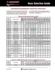
CRIMPER SPECIFICATIONS AND INITIAL SET UPSPECIFICATIONS:MAX HEAD OPENING W/O DIES ------------------------------------------------------------------------350 MM (13.7 IN)MASTER DIE INSIDE DIAMETER -------------------------------------------------------------------------230 MM (9.1 IN)MAXIMUM DIE OPENING ----------------------------------------------------------DIE CLOSED DIAMETER + <strong>12</strong>5 MMCRIMPER SIZE -----------------------------------------------------------------44 IN WIDE X 30 IN DEEP X 74 IN HIGHWEIGHT ------------------------------------------------------------------------------------------------------6185 LB. (2904 KG)ELECTRICAL REQUIREMENTS ----------------------------------------------------220 VOLT 3 PHASE (STANDARD)--------------------------------------------------- 440 VOLT 3 PHASE (OPTIONAL)MOTOR -------------------------------------------------------------------------------------------------7.5 HP (2 STAGE PUMP)RESERVOIR CAPACITY --------------------------------------------------------------------------------------------50 US GALOIL TYPE ----------------------------------------------------------------------------------------------ISO 46 HYDRAULIC OILADAPTER DIES ----------------------------------------------------------230 MM TO 145 MM AND 145 MM TO 99 MMHOSE CAPACITY ----------------------------------------------------------------------------------------2-1/2 INCH 6 SPIRAL--------------------------------------------------------------------------------------10 INCH INDUSTRIALINITIAL CRIMPER SET UP• CHECK RESERVOIR OIL LEVEL WITH SIGHT GLASS ON THE FRONT OF THE POWER UNIT.• CHECK ELECTRICAL CIRCUIT TO BE CERTAIN THAT IT MATCHES THE CRIMPER REQUIREMENTSAS SHOWN ON THE TAG ATTACHED TO THE CRIMPER CORD.• MAKE CERTAIN THAT MOTOR ROTATES IN THE DIRECTION OF THE ARROW SHOWN ON THEMOTOR HOUSING.• IF MOTOR ROTATION IS INCORRECT REVERSE ANY TWO HOT WIRES IN THE CRIMPER PLUG.• CONNECT THE PRESSURE AND RETURN HOSES AS SHOWN AND CONNECT THE YELLOWELECTRICAL CORD TO THE CONTROL PANEL.• ALSO SEE ADDITIONAL INFORMATION ON THE INITIAL SET UP AND MAINTENANCE PAGE.4
AccuCrimp ACT TM CONTROL PANELU.S. Patent No: 7,383,709TOUCH SCREEN CONTROL PANELMANUAL MODE FUNCTION: CLOSE DIESAUTO MODE FUNCTION: CYCLE STARTEMERGENCYSTOPMANUAL MODE FUNCTION: OPEN DIESAUTO MODE FUNCTION: CYCLE STOPNOTE:IF THE CRIMPER IS IN MANUAL MODE, THEGREEN OPEN/CLOSE BUTTONS WILL OPEN ANDCLOSE THE CRIMPER HEAD.IF THE CRIMPER IS IN AUTO MODE, THE BUT-TONS FUNCTION AS CYCLE START AND CYCLESTOP BUTTONS.IF THE CRIMPER IS IN SEMI-AUTO MODE,PRESSING THE FOOT SWITCH OR THE CLOSEBUTTON WILL CLOSE THE CRIMPER HEAD ANDRELEASING WILL HALT THE CLOSING ACTION.5
ACT TM CONTROLLER QUICK STARTWhile the ACT TM crimper has the ability to performa number of fully automatic functions, manualoperation is also possible. To make a manual crimp,two numbers are needed:• The closed diameter of the die (in either inor mm)• The finished crimp diameter (in either in ormm)That’s all you need to know. ACT TM does the rest.TO MAKE A MANUAL CRIMP:• Press START MOTOR.• Select CRIMP TO DIAMETER.• Enter the closed diameter of the die set in either in or mm and press ENTER.Note: for a 25mm die, enter 2500. ACT TM will add 2 decmal places.for a 1.5 inch die, enter 1500, ACT TM will add 3 decimal places.• Enter the finished crimp diameter and press ENTER.• From the ENTER CRIMP screen, press the MANUAL button to put the crimper in manual mode.• Confirm that the die and finished crimp diameters are correct and that MANUAL MODE is displayed.• Press and hold the green close button until the crimper stops closing.• Check the final crimp diameter. If a minor correction is required see HOW TO MAKE MINORCORRECTIONS.Tip: Pressing the CHANGE DIES button allows the crimper head to be fully opened or closed withthe green OPEN-CLOSE buttons on the controller front panel When the CHANGE DIES button isblinking the dies can be opened and closed manually without altering any of the crimper settings.6
HOW TO MAKE MINOR CORRECTIONSDue to variations in hose and fitting tolerances a minor crimpadjustment may be required if the measured diameter of the finalcrimp is not within the hose and fitting manufacturer’s specifications.ACT TM technology makes minor corrections a simple process whichrequires no addition or subtraction.If the fi nished crimp diameter is not within the requiredspecifi cations:• Press the ADJUST CRIMP button.• Enter the measured diameter of the fitting in either inches ormm (Do not enter the amount of correction) and pressENTER• Press SAVE.• Make another crimp and verify that the fitting is withinspecifications.EXAMPLE: If the hose and fi tting manufacturer specifi esthat the fi nished crimp should measure 1.500 to 1.520 andthe measured crimp diameter was 1.530, simply enter themeasured diameter (1530 - Controller will supply 3 decimalplaces) and press SAVE. The fi nished crimp diametercan be entered in either in or mm and ACT TM will make theconversion.While a single correction will usually bring the hose and fittinginto specifications, the process can be repeated as many times as isrequired.7
HOW TO ADD A SAVED DIEUp to 50 different dies can be saved in the computer memory. Thesedies can be recalled in the set up process eliminating the need to reenterthe die size each time.To enter a saved die:• From the OPTION screen, press SETUP MODE.• Select SAVED DIES.• Select the save position (1-50) where the die is to be saved andpress the EDIT button.• Enter a die description (up to <strong>12</strong> alpha/numeric characters).• Enter diameter units (inch or metric).• Enter the closed diameter of the die.• Press SAVE and EXIT.The saved die will now appear on the SELECTED DIEscreen. From this screen individual dies can be cleared or edited.HOW TO RECALL A SAVED DIE• Select CRIMP TO DIAMETER, and from the OPTION screen,select USE SAVED DIE.• Select the saved die (1-50) and press LOAD and then OK.The die parameters will now be used for the crimp process.• From the ENTER CRIMP screen press MANUAL.• The saved die will now be shown on the crimp parametersscreen.8
HOW TO ADD A SAVED CRIMP• Adjust the die diameter and crimp diameter as required andplace the crimper in MANUAL mode.• Press SAVE.• Select a location (1-100) and press EDIT.• Enter a description (up to <strong>12</strong> characters).• Press SAVE and EXIT.The die and crimp setting can now be recalled from thesaved location as required.TO RECALL SAVED CRIMP• Select USE SAVED CRIMP from the option screen.• Select a previously saved crimp from location 1-100.• Press LOAD.The saved crimp will appear on the manual screen.9
FULL AUTO MODEWith the crimper in FULL AUTO mode additional functions areavailable:• The crimper will cycle automatically from the CRIMP button onthe touch screen, the green CYCLE START button on the panel,or the foot switch.• To set the position to which the dies will retract, close thecrimper to the desired retract position prior to pressing theFULL AUTO button.• Pressing the FULL AUTO button will toggle the crimper intoSEMI-AUTO mode. In SEMI-AUTO mode, pressing theFOOT SWITCH or the CLOSE button will close the crimperhead and releasing it will cause the head to stop closing. Thismode allows the crimper to be jogged into position allowingmore precise positioning of a fitting in the dies. Pressing theSEMI AUTO button will toggle the crimper back to FULLAUTO mode.In FULL AUTO mode pressing the foot switch will start the crimpcycle and the dies will stop closing when the crimp cycle is complete• The COUNT function is activated allowing the operator tomonitor the number of crimps made.• A measurement can be required after a preset number ofcrimps. See SET REQUIRED MEASUREMENT.SET REQUIRED MEASUREMENT• Press the PRODUCTION button.• Determine if 1 or 2 crimps will count as a crimp.• Toggle the CRIMP ADJUSTMENT REMINDER to ON.• Set the COUNTS BETWEEN CRIMP MEASUREMENTSto the desired number and press OK.• At the set interval, the ADJUST CRIMP screen will come upand the operator will be asked to measure the last crimp andenter a correction if required.10
ADJUST CRIMP COUNTIf a production operation is interrupted for some reason, it is possibleto reset the counter to where the operation was at the point ofinterruption.• Press the Adjust Count button from the auto crimp screen.• Press the Crimp Counter and reset the count to the desiredpoint.ACT TM ADDITIONAL FEATURES• Additional features and functions of the ACT TM controller can beaccessed by pressing the MORE button on the MACHINE SETUP screen.• When “Allow Crimp to Diameter” is set to “YES”, all of theadjustment functions of the crimper are available. When“Allow Crimp to Diameter” is set to “NO” only the settingsentered as a saved crimp can be used.• English or Spanish language options are available.• The “Use Pressure Compensation” is set to “YES” for allcrimpers equipped with a pressure transducer. A security code isrequired to turn this function on or off.11
ACT TM ADDITIONAL FEATURESPre-Loaded Crimp SpecificationsIn addition to the ability to store up to 50 user entereddies and 100 user entered crimp settings, the ACT TMController has the capability of accepting pre loadedmanufacturer’s crimp specifications. CustomCrimp®does not maintain these specifications as theyare proprietary to the individual hose and fittingmanufacturer. If, however, your ACT TM Controller waspre loaded with a manufacturer’s crimp specificationsor if they are available to you, they are accessed in thefollowing manner:• Press the Crimp Memory Table Button.• Press the access button to bring up the stored crimpspecifications.• Scroll through the crimp specifications to select thecorrect one. The right hand rocker button movesthrough the crimp specs one line at a time and the lefthand rocker button moves one screen at a time.• When the correct crimp specification is selected,press the highlighted selection and then the Loadbutton and select OK to write the data to the ACT TMController.• This will bring up the familiar crimp screen and thecrimper can then be operated in the normal manner.<strong>12</strong>
DIE INSTALLATION AND REMOVALAdapter Die Installation230 mm to 145 mm and 145 mm to 99 mm Adapter Dies are available withthe crimper. Adapter dies are held in place by the locking screws as shown inthe illustration. Hydraulic dies can either be installed manually or with the dieremoval tool as shown.The I.D. of intermediate adapter dies must match the O.D. of thecorresponding adapter die or hydraulic die or accurate crimps can not bemade.Hydraulic Die Installation• Install the 230mm to 145mm and 145mm to 99mm Intermediate AdapterDies as shown making certain that the Intermediate Adapter Die I.D.matches the Hydraulic Die O.D.• Remove the Hydraulic Dies from their holder with the magnetic dieinsertion tool as shown.• The die size stamped on the face of the die should face toward the operator.• Align the studs of the Hydraulic Dies with the holes in the Adapter Dies andwith the crimper in manual mode SLOWLY close the crimper head on thedie set.• Bring the crimper head to a fully closed position and remove the dieinsertion tool.The dies may also be inserted manually with the crimper head in the fully openposition.Proceed to the ACT TM operating instructions to set up the crimper for the hoseand fitting being crimped.For Hydraulic Die removal, place the crimper in manual mode and bring thecrimper head to the fully closed position. Insert the die removal tool and openthe crimper head releasing the Hydraulic Dies from their spring retention holes.Press the CHANGE DIES button on the controller to easily open andclose the master dies without affecting crimper settingsNote that on the CC<strong>1000</strong>, the master dies must be slightly closed inorder to completely insert the die removal tool.13
INITIAL SET UP AND PLC RESETInitial SetupCheck to be certain that the motor rotates in the direction of the arrow shownon the motor housing. If motor rotation is opposite of the direction of thearrow, reverse any two hot wires in the electrical plug.Damage to the pump can result if the motor does not rotate in the correctdirection.Check the oil level in the sight glass on the front of the tank. 50 U.S. gallonsof ISO 46 hydraulic oil are required to completely refill the tank.Oil can be drained from either of the two ports at the bottom of the tank.An additional oil cooler, while not normally required, can be plumbed intothe two ports at the rear of the tank.LubricationLubricate the crimping head after each 100 crimping cycles or at the start ofeach shift if the crimper is used in a production setting.Bring the master dies to the fully closed position, and lubricate the masterdies through the 8 holes in the protective plates as illustrated.Use only a high quality grease. Failure to do so may result in damage to thewearing surfaces.PLC Reset ProcedureThe PLC (Programmable Logic Controller) requires a relatively constantsource of electrical power. Power surges, outages or drops in power cancause the PLC to lose its settings. This may result in missing or misplacedinformation on the controller screen.Resetting the PLC to its originalsettings is a simple procedure• Turn the main power switch to OFF.• Open the front of the Control Panel.• Power up the crimper from the main powerswitch. The crimper must be powered onduring the PLC reset procedure.• Move the three position toggle switch on topof the PLC right to the STOP position and then left to the RUN position.• Return the toggle switch to the center TERM position.• Repeat for the other PLC Unit.• Turn the main power switch to OFF and replace the front panel.• The PLC and the crimper should now operate normally.14
TROUBLESHOOTINGPROBLEM: CRIMPER WILL NOT RUN AT ALL• Check the E-Stop switch to be certain that it is not depressed. A slight twist is required to release switch after ithas been depressed.• PLC (Programmable Logic Control) must be reset. See instructions on the previous page.PROBLEM: CRIMPER RUNS BUT IS SLOW OR NON-FUNCTIONAL• Check supply voltage to see that it matches the voltage specified on the tag attached to the crimper.Many performance problems are the result of low voltage or inadequate electrical service.• Check motor rotation and be certain that the motor rotates in the direction of the arrow on the motor housing. Forthree phase units rotation can be reversed by switching any two wires in the plug.PROBLEM: CRIMPER WILL CLOSE ON FITTING BUT DOESNOT DEVELOP POWER TO COMPLETE THE CRIMP• Check oil level. Position dies to the fully open position and check oil sight gage in rear of machine. Be sure theoil level is in the middle of the sight glass. Use ISO 32 or 46 weight hydraulic oil.PROBLEM: CRIMPER WILL NOT OPEN TO RETRACT POSITION IN AUTO MODE• Retract position must be at least 3 mm larger than the final crimp diameter.If problems persist contact Customer Service for additional troubleshootingassistance15
EXPLODED PARTS VIEW57CC<strong>1000</strong> SHEET METAL ASSEMBLYITEM PART NUMBERDESCRIPTIONQTY1 103204-1 CC<strong>1000</strong> FRONT PANEL <strong>12</strong> 103209 CC<strong>1000</strong> PROTECTIVE SLIDE PLATE 23 103214CC<strong>1000</strong> BACK PANEL 14 103236 CC<strong>1000</strong> PROTECTIVE PLATE WRAP 25 103219 CC<strong>1000</strong> TOP FRAME WRAP 16 9<strong>12</strong>39A318M6 X <strong>12</strong> BHCS247 9<strong>12</strong>39A321M6 X 16 BHCS28 10<strong>12</strong>4299S DIE HOLDER159 9<strong>12</strong>51A5401/4-20 x 3/4 SHCS6010 103208CC<strong>1000</strong> BASE LEG211 9<strong>12</strong>90A626M<strong>12</strong> X 50 SHCS842361698261016
EXPLODED PARTS VIEW436528TORQUE TO305 FT/LBS911<strong>12</strong>71CC<strong>1000</strong> WEAR PLATE ASSEMBLYITEM PART NUMBERDESCRIPTIONQTY1 103146CC<strong>1000</strong> FRAME<strong>12</strong> 103150CC <strong>1000</strong> SLIDING V PLATE 13 103157 CC <strong>1000</strong> MASTER DIE WEAR PLATE 44 9<strong>12</strong>94A328M10 X 20 FHCS85 103163 CC <strong>1000</strong> STATIONARY WEAR PLATE 26 9<strong>12</strong>94A242M6 X 25 FHCS87 103158 CC <strong>1000</strong> CYLINDER ASSEMBLY 18 9<strong>12</strong>90A837M16 X 70 SHCS19 103206-L CC<strong>1000</strong> LEFT SUPPORT LEG ASMB. 210 103206-R CC<strong>1000</strong> RIGHT SUPPORT LEG ASMB. 211 9<strong>12</strong>90A626M<strong>12</strong> X 50 SHCS8<strong>12</strong> 91166A290M<strong>12</strong> WASHER810<strong>17</strong>
EXPLODED PARTS VIEWCC<strong>1000</strong> PROTECTIVE PLATES AND GUIDES ASSEMBLYITEM PART NUMBERDESCRIPTIONQTY1 103146CC<strong>1000</strong> FRAME<strong>12</strong> 103193CC <strong>1000</strong> SIDE GUIDE PLATE43 9<strong>12</strong>90A620M<strong>12</strong> X 35 SHCS684 9<strong>12</strong>90A432M8 X 25 SHCS85 103196CC <strong>1000</strong> MASTER DIE COVER PLATE 86 9<strong>12</strong>94A284M8 X 20 FHCS167 103248CC<strong>1000</strong> POTENTIOMETER BRACKET 18 9<strong>12</strong>90A626M<strong>12</strong> X 50 SHCS29 9<strong>12</strong>90A820M16 X 50 SHCS110 103230 CC<strong>1000</strong> PROTECTIVE PLATE ALIGNMENT TABS 411 103473CC600/<strong>1000</strong> ROLLER LIMIT SWITCH 1<strong>12</strong> 103349CC600/<strong>1000</strong> ADJUSTABLE BRACKET 113 103448CC<strong>1000</strong> PROTECTIVE PLATE KEY 414 103472 CC600/CC<strong>1000</strong> LINEAR POTENTIOMETER 115 9<strong>12</strong>51A24410-24 x 5/8 SHCS216 9<strong>12</strong>51A34510-24 X 3/4 SHCS2<strong>17</strong> 9<strong>12</strong>55A54910-24 ROUND WASHER218 9<strong>12</strong>90A<strong>17</strong>6M4 X 25 SHCS419 9<strong>12</strong>94A237M6 X 14 FHCS820 9<strong>12</strong>90A548M10 X 100 SHCS3143413192<strong>12</strong>16<strong>17</strong>206 51571181814918
EXPLODED PARTS VIEW432<strong>12</strong>3576CC<strong>1000</strong> MASTER DIE ASSEMBLYITEM PART NUMBERDESCRIPTIONQTY1 103147 CC<strong>1000</strong> MASTER DIE CARRIER 42 103249 CC<strong>1000</strong> MASTER DIE ALIGNMENT NUT 403 9<strong>12</strong>90A144M4 X 10 SHCS404 9<strong>12</strong>90A446M8 X 45 SHCS85 103156CC<strong>1000</strong> MASTER DIE SHOE 86 103470DIE SPRING247 9<strong>12</strong>90A548M10 X 100 SHCS219
EXPLODED PARTS VIEW32415876CC<strong>1000</strong> MIRROR BRACKET ASSEMBLY (103161-3)ITEM PART NUMBERDESCRIPTIONQTY1 103219CC<strong>1000</strong> SHEET METAL WRAP<strong>12</strong> 103307 CC600/<strong>1000</strong> MIRROR BRACKET SUPPORT ARMS 43 103345 CC600/<strong>1000</strong> MIRROR ATTACHMENT BRACKET 14 103471<strong>12</strong>" X <strong>12</strong>" MIRROR15 9<strong>12</strong>39A620M<strong>12</strong> X 40 BHCS26 9<strong>12</strong>55A6243/8-16 X 1 BHCS27 94846A0313/8-16 HEX NUT28 9<strong>12</strong>55A6263/8-16 X 1 1/4 BHCS220
EXPLODED PARTS VIEW14915<strong>17</strong>516413211610<strong>12</strong>83CC600/<strong>1000</strong> TOWER ASSEMBLYITEM PART NUMBERDESCRIPTIONQTY1 7309K342CC600/<strong>1000</strong> TOWER BOX<strong>12</strong> 103308-1 CC600/<strong>1000</strong> TOWER SWIVEL BRACKET 13 103308-2 CC600/<strong>1000</strong> TOWER SUPPORT ARM 14 103308-3 CC600/<strong>1000</strong> TOWER MOUNTING BRACKET 15 9<strong>12</strong>55A24210-24 X 1/2" BHCS46 9<strong>12</strong>55A5401/4 - 20 x 3/4" BHCS47 KHA-1501/2-13 LOCKING HANDLE18 KHA-1081/4-20 LOCKING HANDLE<strong>12</strong>1
KD<strong>1000</strong> WARRANTYCustomCrimp “No-Nonsense” WarrantyStatementAll CustomCrimp Products are warranted to be free of defects in workmanship andmaterials for one year from the date of installation. This warranty ends when the productbecomes unusable for reasons other than defects in workmanship or material.Any CustomCrimp Product proven to be defective in workmanship or material will berepaired or replaced at no charge. To obtain benefi ts of this warranty, fi rst, contactWarranty Repair Department at Custom Machining Services at (219) 462-6<strong>12</strong>8 and thendeliver via prepaid transportation the complete hydraulic product to:ATTN: WARRANTY REPAIR DEPT.Custom Machining Services, Inc.326 North Co. Rd 400 EastValparaiso IN 46383If any product or part manufactured by CustomCrimp is found to be defective byCustomCrimp, at its option, CustomCrimp will either repair or replace the defective partor product and return via ground transportation, freight prepaid. Custom Crimp will notcover any incoming or outgoing freight charges for machines sold outside TheUnited States.This warranty does not cover any product or part which is worn out, abused, altered,used for a purpose other than for which it was intended, or used in a manner which wasinconsistent with any instructions regarding its use.Electric motors are separately warranted by their manufacturer under the conditionsstated in their separate warranty.22