Zenith® Pumps 9000 Series Gear Pumps - LUBOSA
Zenith® Pumps 9000 Series Gear Pumps - LUBOSA
Zenith® Pumps 9000 Series Gear Pumps - LUBOSA
- No tags were found...

Create successful ePaper yourself
Turn your PDF publications into a flip-book with our unique Google optimized e-Paper software.
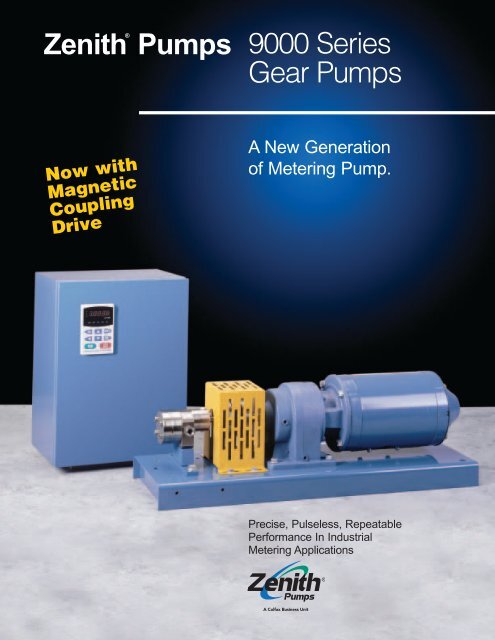
Zenith® <strong>Pumps</strong><strong>9000</strong> <strong>Series</strong><strong>Gear</strong> <strong>Pumps</strong>Now withMagneticCouplingDriveA New Generationof Metering Pump.Precise, Pulseless, RepeatablePerformance In IndustrialMetering Applications
<strong>9000</strong> <strong>Series</strong>The Zenith <strong>9000</strong> <strong>Series</strong> was developedas a true precision metering gear pumpfor application into a variety of industrialprocesses. The design utilizes high AGMAstandard external spur gears of optimumgeometry, enclosed within a close tolerancehousing assembly, resulting in aprecise volume of fluid dispensed pershaft revolution.The housing is constructed from aprecision ground and lapped 3-plateassembly. The plate assembly is alignedwith dowels to allow close control of operatingclearances. This construction methodin combination with several proprietaryinternal features is what ensures Precise,Pulseless and Reliable flow under varyingprocess conditions.Coupled with a pre-packagedintegrated closed loop speed controland compact motor driver assembly (ACor DC), Zenith is able to provide the mostprecise and flexible metering gear pumpon the market.Zenith <strong>Pumps</strong> has been designing andmanufacturing precision metering gearpumps since it’s inception in 1926. Overthe years’ Zenith has been distinguishedas an innovator in the application of gearpump technology by a variety of industriesand end-users. The <strong>9000</strong> series is Zenith’slatest generation of industrial meteringpumps that are based upon years ofpractical application knowledge, andpioneering research and development.For years, engineers have relied onZenith to provide Precision Fluid HandlingSolutions for the most difficult pumpingapplications. This is why Zenith gearpumps can be found wherever Precise,Pulseless and Reliable fluid meteringperformance is required. Please review thefollowing with this in mind, and be sure tocontact us to discuss your specific needs— we are here to help make your meteringapplications simpler for you and yourcustomers.ApplicationSamplesfrom A to ZAdhesivesAdditivesAcids & BasesAbrasivesAsphaltBeveragesBiotechBottomsBonding AgentsCalcium StearateCandyCatalystsChemicalsCoatingsColorantsCosmeticsCerealDe-ionized WaterDyesDefoamerDetergentsEmulsionsEpoxiesFibersFlavoringsFragrancesFuelsFoodstuffFoamsGasketingGlycolsHot MeltsInksInhibitorsInjectionJuicesKeroseneLubricantsMineral OilMonomersNutrientsOilsOligomersOxide SlurriesPaintsPerfumesPharmaceuticalsPill CoatingsPolymersPlasticsPolyurethanesPlasticizersPolyolsPigmentsPottingPitchQuartz SlurriesResinsSealantsSiliconesSolventsSurfactantsSlurriesSprayingTackifiersTarUrethanesVarnishViscoseVitaminsWater SolutionsWater TreatmentWaxesXyleneYeastZinc Oxideand many,many more…BenefitsHigh Accuracy: Stable repeatable flowsare assured under varying conditionsof temperature, viscosity and pressure.Uniform Metered Flow: Unique design offersvirtually pulseless flow, without valves orflexible elements that add complexities,increase cost and hinder performance.Engineered Solutions: Proven Applications:A variety of pump heads and drivercombinations have been pre-configuredto provide a range of standard installationoptions, meeting OSHA, UL, EC and DinStandards.Active Flowmeter Concept: Unparalleledmechanical precision, combined withclosed loop accuracy, ensures exactvolume per revolution without expensiveflow meters.Low Cost of Ownership: Only three movingparts, and hardened abrasion resistantmaterials provide excellent wear, corrosionand self-lubricating performance.Proven Applications: Years of practicalapplication experience, backed by atechnical staff with a variety of technicalcredentials eliminates the guesswork.2
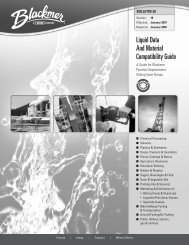
Pump Head Options:B-<strong>9000</strong> <strong>Series</strong>: General-purpose industrial dutyConstructed of through hardened 400 series stainless steelCapacities (cc/rev): 0.05, 0.3, 0.6, 1.2, 2.4, 4.5, 9.0,15, 30, 45, 90Recommended Speed: .05 to 30 cc/rev, up to 500 RPM45 & 90 cc/rev, up to 300 RPMFlow Range: up to 27,000 cc/Minuteup to 7 gpmInlet Pressure: 300 psi (20 Bar) MaximumOutlet Pressure: 1000 psi (70 Bar) MaximumDifferential Pressure: 20 to 1000 psi. (viscositydependent)Temperature: 0° F (-18° C) Minimum400° F (205° C) Maximum (withmagnetic coupling seal)645° F (340° C) Maximum(dependant on shaft sealmaterials)Seals: Single Mechanical, Double Lip, Packedor MagneticRotation: Clockwise (CW) facing drive shaftPort Connections:Metric thread or SAE 61 StandardOptional Port Adapters:M12 X 1/4" NPT . . . . . . . . . . 0.05 – 2.4 cc/rev1/2" SAE X 1/2" NPT . . . . . . 4.5 – 9.0 cc/rev3/4" SAE X 3/4" NPT . . . . . . 15 – 30 cc/rev1-1/4" SAE X 1-1/4" NPT . . 45 – 90 cc/revOptional Band heaters:150 Watt, 115 VAC . . . . . . . 0.05 – 2.4 cc/rev325 Watt, 115 VAC . . . . . . . 4.5 – 9.0 cc/rev650 Watt, 230 VAC . . . . . . . 15 – 30 cc/rev1500 Watt, 230 VAC . . . . . . 45 – 90 cc/revC-<strong>9000</strong> <strong>Series</strong>: Corrosive & Poor Lubricating FluidsConstructed of hardened 316SS and compatible materialsCapacities (cc/rev): 0.3, 0.6, 1.2, 2.4, 4.5, 9.0Recommended Speed: up to 1000 rpmFlow Range: up to 9,000 cc/Minuteup to 2.4 gpmInlet Pressure: 300 psi (20 Bar) MaximumOutlet Pressure: 1000 psi (70 Bar) MaximumDifferential Pressure: 20 to 1000 psi. (viscositydependent)Temperature: -40° F (- 40° C) Minimum350° F (175° C) MaximumSeals: Single Mechanical, Double Lip, or MagneticRotation: Clockwise (CW) facing drive shaftPort Connections:Metric thread or SAE 61 StandardOptional Port Adapters:M12 X 1/4" NPT . . . . . . . . . . 0.3 – 2.4 cc/rev1/2" SAE X 1/2" NPT . . . . . . 4.5 – 9.0 cc/revOptional Band heaters:150 Watt, 115 VAC . . . . . . . 0.3 – 2.4 cc/rev325 Watt, 115 VAC . . . . . . . 4.5 – 9.0 cc/revH-<strong>9000</strong> <strong>Series</strong>: High Temperature and Abrasive FluidsConstructed of through-hardened high speed tool steelsCapacities (cc/rev): 0.3, 0.6, 1.2, 2.4, 4.5, 9.0, 15, 30,45, 90Recommended Speed: 0.3 to 30 cc/rev, up to 500 RPM45 & 90 cc/rev, up to 300 RPMFlow Range: up to 27,000 cc/Minuteup to 7 gpmInlet Pressure: 1000 psi (70 Bar) MaximumOutlet Pressure: 2500 psi (175 Bar) MaximumDifferential Pressure: 20 to 2500 psi. (viscositydependent)Temperature:32° F (0.0° C) Minimum950° F (510° C) Max. (With packingseal and high temperaturefasteners)Seals: Single Mechanical, Double Lip seal orPacked configurationsRotation: Clockwise (CW) facing drive shaftPort Connections:Metric thread or SAE 61 StandardOptional Port Adapters:M12 X 1/4" NPT . . . . . . . . . . 0.3 – 2.4 cc/rev1/2" SAE X 1/2" NPT . . . . . . 4.5 – 9.0 cc/rev3/4" SAE X 3/4" NPT . . . . . . 15 – 30 cc/rev1-1/4" SAE X 1-1/4" NPT . . 45 – 90 cc/revOptional Band heaters:150 Watt, 115 VAC . . . . . . . 0.3 – 2.4 cc/rev325 Watt, 115 VAC . . . . . . . 4.5 – 9.0 cc/rev650 Watt, 230 VAC . . . . . . . 15 - 30 cc/rev1500 Watt, 230 VAC. . . . . . 45 - 90 cc/rev3
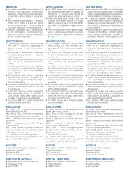
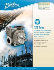
Standard Metering Systems (shown with ZVD AC Controller)• 1/2 - 2 HP AC Vector Drive• 230 VAC, 1 or 3 phase (1/2 – 2 HP)• 460 VAC 3 phase• Closed loop PID control• Engineering unit orfrequency setpoint• Jog• 5 standard inputs• 6 multifunction inputs• 1 form C relay multifunctionoutput• 3 open collector multifunctionoutputs• Password protection• Adjustable current limit• RS-485 Modbus serialcommunications• Analog I/OFHUVFD-PUO1RUN STOP JOG FWD REVJOGMODEPROGDATASTOPRUN RESET12.00/292.816.00/406.4Note: All standard systems include NPT portadapters. See dimensions “L” and “Z” in the chartbelow for details. If the NPT adapters are removed,refer to individual pump drawings for information onport connections.Note: ZeDrive DC controllers and motors are alsoavailable. For more information, please visitwww.zenithpumps.com1.00"/25,4"H"4X Ø0.56/14,2Mounting Hole Scheme1.00/24,4"I"1.8:13:15:111:122:1"X"BothSides4X "W" TapBoth Sides"Z" PortBoth Sides"Y" Both SidesPumpPort C/LBoth Sides"B""E""L"ROTATION"J"DriveC/L"D"2.00"K""V" (Max)See Note Above"A""C" Both Sides"F""G"System/Dim. A B C D E F G H I J K L V W X Y ZNEMAIEC1/2 hp28.00 5.28 3.39 3.74 9.00 4.75 9.50 26.00 7.50 2.76 4.65 4.40 0.17 N/A N/A N/A 1/4 NPT 56C.05-2.4cc/rev* 711.2 134.1 86.1 95.0 228.6 120.7 241.3 660.4 190.5 70.1 118.1 111.8 4.3 N/A N/A N/A 1/4 NPT 711/2 hp 28.00 5.11 2.98 4.11 9.00 4.75 9.50 26.00 7.50 3.94 5.07 6.44 0.17 M8 x 12DP 0.69 1.50 1/2 NPT 56C4.5-9cc/rev* 711.2 129.8 75.7 104.4 228.6 120.7 241.3 660.4 190.5 100.1 128.8 163.6 4.3 M8 x 12DP 17.5 38.1 1/2 NPT 711 hp36.00 5.86 8.22 4.51 10.01 5.00 10.00 34.00 8.00 3.94 5.82 6.44 N/A M8 x 12DP 0.69 1.50 1/2 NPT 56C4.5-9cc/rev* 914.4 148.8 208.8 114.6 254.3 127.0 254.0 863.6 203.2 100.1 147.8 163.6 N/A M8 x 12DP 17.5 38.1 1/2 NPT 802 hp36.00 5.86 8.22 4.51 10.01 5.00 10.00 34.00 8.00 3.94 5.82 6.44 3.37 M8 x 12DP 0.69 1.50 1/2 NPT 145TC4.5-9cc/rev* 914.4 148.8 208.8 114.6 254.3 127.0 254.0 863.6 203.2 100.1 147.8 163.6 85.6 M8 x 12DP 17.5 38.1 1/2 NPT 901/2 hp36.00 5.19 7.63 4.11 9.61 5.00 10.00 34.00 8.00 5.00 5.69 7.50 N/A M10 x 22DP 0.88 1.88 3/4 NPT 56C15-30cc/rev ‡ 914.4 131.8 193.8 104.4 244.1 127.0 254.0 863.6 203.2 127.0 144.5 190.5 N/A M10 x 22DP 22.4 47.8 3/4 NPT 711 hp36.00 5.60 7.55 4.51 10.01 5.00 10.00 34.00 8.00 5.00 6.10 7.50 N/A M10 x 22DP 0.88 1.88 3/4 NPT 56C15-30cc/rev ‡ 914.4 142.2 191.8 114.6 254.3 127.0 254.0 863.6 203.2 127.0 154.9 190.5 N/A M10 x 22DP 22.4 47.8 3/4 NPT 802 hp36.00 5.60 7.55 4.51 10.01 5.00 10.00 34.00 8.00 5.00 6.10 7.50 N/A M10 x 22DP 0.88 1.88 3/4 NPT 145TC15-30cc/rev ‡ 914.4 142.2 191.8 114.6 254.3 127.0 254.0 863.6 203.2 127.0 154.9 190.5 N/A M10 x 22DP 22.4 47.8 3/4 NPT 901 hp36.00 6.14 6.12 5.38 10.89 5.00 10.00 34.00 8.00 6.89 7.59 9.37 N/A M12 x 24DP 1.19 2.31 1-1/4 NPT 56C45-90cc/rev ‡ 914.4 156.0 155.4 136.7 276.6 127.0 254.0 863.6 203.2 175.0 192.8 238.0 N/A M12 x 24DP 30.2 58.7 1-1/4 NPT 802 hp36.00 6.14 6.12 5.38 10.89 5.00 10.00 34.00 8.00 6.89 7.59 9.37 N/A M12 x 24DP 1.19 2.31 1-1/4 NPT 145TC45-90cc/rev ‡ 914.4 156.0 155.4 136.7 276.6 127.0 254.0 863.6 203.2 175.0 192.8 238.0 N/A M12 x 24DP 30.2 58.7 1-1/4 NPT 9*Available for B-<strong>9000</strong>, C-<strong>9000</strong> and H-<strong>9000</strong>,4‡Available for B-<strong>9000</strong> and H-<strong>9000</strong>
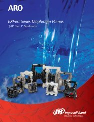
ZENITH ® PUMPSRUNSTOPANALOGREMOTEZeDRIVE 2000<strong>9000</strong> MD Systems (shown with ZeDrive DC Controller)• 1 / 4 – 2 HP SCR DC Drive• 115 VAC, 1 phase (90 VDC Motors)• 230 VAC, 1 phase (180 VDC Motors)• Master or Follower Modes• Closed loop PID control• 4 engineering unit setpoints• Jog• 13 standard inputs• 5 open collector outputs• Keypad lockout• Adjustable current limit• RS-422 serialcommunications• Optional Analog I/O (12 bit)<strong>9000</strong>MDDirect DriveMagneticCoupling<strong>9000</strong>MDMagneticCouplingwith reducerEVEVDC MotorOverhang4 Mounting Holes3/8 In/.97mmDia ThruCODE ENTER CLEAR1 2 34 5 67 8 903.65±.038.00/203.2 1.00/25.410.00/254.0AA1.8:13:15:111:122:1PanelCutout7.25±.03.38/9.512.75/323.913.50/342.9CXNote: All standard systems include NPT port adapters.See dimensions “L” and “Z” in the chart below for details.If the NPT adapters are removed, refer to individualpump drawings for information on port connections.Note: ZVD AC controllers and motors are alsoavailable. For more information, please visitwww.zenithpumps.comCKWYB1.00"/25,4"H"4X Ø0.56/14,2Mounting Hole SchemeFFROTATIONJLGROTATIONL JGPort2 PlacesDriveC/LD2.00KPort2 PlacesDrive KC/LD2.001.00/24,4"I"System Coupling NEMAConfiguration Torque "A" "B" "C" "D" "E" "F" "G" "H" "I" "J" "K" "L" "V" "W" "X" "Y" "Z" IEC0.05 - 2.4 cc/rev23 in-lb 24.00 5.01 4.50 5.47 11.20 5.00 10.00 22.00 8.00 2.76 4.38 4.45 N/A N/A N/A N/A 1/4 NPT 56-C1/2 HP Direct Drive 609.60 127.25 114.30 138.94 284.48 127.00 254.00 558.80 203.20 70.10 111.25 113.03 N/A N/A N/A N/A 1/4 NPT 710.05 - 2.4 cc/rev23 in-lb 30.00 5.47 4.50 5.94 11.70 5.00 10.00 28.00 8.00 2.76 4.85 4.45 N/A N/A N/A N/A 1/4 NPT 56-C1/2 HP with Reducer 762.00 138.94 114.30 150.88 297.18 127.00 254.00 711.20 203.20 70.10 123.19 113.03 N/A N/A N/A N/A 1/4 NPT 710.05 - 2.4 cc/rev55 in-lb 24.00 5.01 4.50 5.47 11.20 5.00 10.00 22.00 8.00 2.76 4.38 4.45 N/A N/A N/A N/A 1/4 NPT 56-C1 HP Direct Drive 609.60 127.25 114.30 138.94 284.48 127.00 254.00 558.80 203.20 70.10 111.25 113.03 N/A N/A N/A N/A 1/4 NPT 800.05 - 2.4 cc/rev55 in-lb 30.00 5.47 4.50 5.94 11.70 5.00 10.00 28.00 8.00 2.76 4.85 4.45 0.09 N/A N/A N/A 1/4 NPT 56-C1 HP with Reducer 762.00 138.94 114.30 150.88 297.18 127.00 254.00 711.20 203.20 70.10 123.19 113.03 2.29 N/A N/A N/A 1/4 NPT 804.5 - 9.0 cc/rev110 in-lb 24.00 4.84 4.00 5.47 11.20 5.00 10.00 22.00 8.00 3.94 4.81 6.50 N/A M8 x 12DP 0.69 1.50 1/2 NPT 56-C1/2 HP Direct Drive 609.60 122.94 101.60 138.94 284.48 127.00 254.00 558.80 203.20 100.08 122.17 165.10 N/A M8 x 12DP 17.53 38.10 1/2 NPT 714.5 - 9.0 cc/rev110 in-lb 30.00 5.28 3.44 5.94 11.70 5.00 10.00 28.00 8.00 3.94 5.25 6.50 N/A M8 x 12DP 0.69 1.50 1/2 NPT 56-C1/2 HP with Reducer 762.00 134.11 87.38 150.88 297.18 127.00 254.00 711.20 203.20 100.08 133.35 165.10 N/A M8 x 12DP 17.53 38.10 1/2 NPT 714.5 - 9.0 cc/rev110 in-lb 24.00 4.84 4.00 5.47 11.20 5.00 10.00 22.00 8.00 3.94 4.81 6.50 0.06 M8 x 12DP 0.69 1.50 1/2 NPT 56-C1 HP Direct Drive 609.60 122.94 101.60 138.94 284.48 127.00 254.00 558.80 203.20 100.08 122.17 165.10 1.52 M8 x 12DP 17.53 38.10 1/2 NPT 804.5 - 9.0 cc/rev110 in-lb 30.00 5.28 3.44 5.94 11.70 5.00 10.00 28.00 8.00 3.94 5.25 6.50 0.17 M8 x 12DP 0.69 1.50 1/2 NPT 56-C1 HP with Reducer 762.00 134.11 87.38 150.88 297.18 127.00 254.00 711.20 203.20 100.08 133.35 165.10 4.32 M8 x 12DP 17.53 38.10 1/2 NPT 804.5 - 9.0 cc/rev110 in-lb 24.00 4.84 4.00 5.47 11.20 5.00 10.00 22.00 8.00 3.94 4.81 6.50 3.36 M8 x 12DP 0.69 1.50 1/2 NPT 140TC2 HP Direct Drive 609.60 122.94 101.60 138.94 284.48 127.00 254.00 558.80 203.20 100.08 122.17 165.10 85.34 M8 x 12DP 17.53 38.10 1/2 NPT 94.5 - 9.0 cc/rev110 in-lb 30.00 5.28 3.44 5.94 11.70 5.00 10.00 28.00 8.00 3.94 5.25 6.50 2.77 M8 x 12DP 0.69 1.50 1/2 NPT 140TC2 HP with Reducer 762.00 134.11 87.38 150.88 297.18 127.00 254.00 711.20 203.20 100.08 133.35 165.10 70.36 M8 x 12DP 17.53 38.10 1/2 NPT 95
1) Select Pump ModelB-<strong>9000</strong> C-<strong>9000</strong> H-<strong>9000</strong>Typical Service General Chemical ✔ — —Corrosive/Poor Lubricity — ✔ —Abrasive/High Temperature — — ✔Materials 400 <strong>Series</strong> Stainless Steel ✔ — —316 Stainless Steel — ✔ —Tool Steel — — ✔Outlet Pressure ≤ 1000 psi ✔ ✔ ✔1000 ≤ 2500 psi — — ✔Inlet Pressure ≤ 300 psi ✔ ✔ ✔300 ≤ 1000 psi — — ✔Temperature ≤ 350 F ✔ ✔ ✔≤ 645 F ✔ — ✔≤ 950 F — — ✔Viscosity ≤ 1 cps — ✔ —≥ 1 cps ✔ ✔ ✔Flow Rate ≤ <strong>9000</strong> cc/min ✔ ✔ ✔≤ 27000 cc/min ✔ — ✔Lubricity Abrasive (Tio2 etc.) — — ✔Poor (Solvents etc.) — ✔ —Good (Polyols etc.) ✔ ✔ ✔Excellent (Oils etc.) ✔ ✔ ✔pH Low (< 7) — ✔ —Neutral (7) ✔ ✔ ✔High (> 7) ✔ ✔ —2) Select Maximum Operating SpeedOperating ConditionsSuggested Maximum Speed (RPM)Lubricity Viscosity B-<strong>9000</strong> C-<strong>9000</strong> H-<strong>9000</strong>Excellent < 1,000 cps < 500 < 1000 < 500Good to Excellent 1000 < 10,000 cps < 300 < 500 < 300Poor to Excellent > 10,000 cps < 150 < 150 < 150Abrasive (Consult Zenith) > 1 cps — — < 753) Select Pump Size1) Maximum Flow (cc/min) ÷ Maximum Operating Speed = Pump Capacity (cc/rev).2) Round up to the next largest pump size. See page 3 for available sizes.3) Calculate Minimum Operating Speed (rpm) = Minimum Flow (cc/min) ÷ Pump Capacity (cc/rev).4) Select Reducer Ratio (All Systems) or Direct Drive (Magnetic Drive Systems Only)Select a reducer ratio and speed range that best fits the maximum and minimum operating speedscalculated in steps 2 and 3.6Pump Speed Range with 1800 rpm Motor, 20:1 TurndownSpeed Range (n – N) 90 - 1800* 50 - 1000 30 - 600 18 - 360 8 – 164 4 - 82Reducer Ratio 1:1 (Direct) 1.8:1 3:1 5:1 11:1 22:1* Note: maximum recommended pump speed is 1000 rpm or less.5) Calculate Maximum Pump Torque Requirements1) Pump Torque: T (in-lbs) = (K 1 • ∆P (psi)) + (K 2 • N • µ / 100,000) orT (Nm) = (k 3 • ∆P (kg/cm 2 )) + (K 4 • N •µ / 100,000)K 1 , K 2 , K 3 & K 4 = Constants from adjacent chart∆P = Differential Pressure (Outlet Pressure – Inlet Pressure)N = Maximum Pump Speed, based on Reducer Ratio. See step 4.µ = Viscosity (cps). Note: for shear thinning fluids, consult Zenith.2) Compare the calculated torque to the maximum torque shown inthe adjacent chart. The calculated torque must not exceed themaximum torque.3) For magnetic drive systems, the calculated torque cannot exceedthe maximum torque rating of the magnetic coupling. See page 5 fortorque limits and available system configurations.Capacity(cc/rev)Max. Torque*K 1/ K 2 K 3/ K 4(in-lbs/NM)0.05 0.0005/0.85 0.0008/0.096 7.5/.850.3 0.003/2.11 0.004/0.24 90/100.6 0.006/2.34 0.010/0.26 200/231.2 0.012/2.82 0.018/0.32 200/232.4 0.023/3.78 0.037/0.43 200/234.5 0.044/6.85 0.070/0.77 400/459.0 0.087/8.56 0.141/0.97 400/4515.0 0.146/14.66 0.233/1.66 600/6830.0 0.291/18.57 0.468/2.10 600/6845.0 0.437/32.78 0.701/3.70 1950/22090.0 0.873/30.61 1.404/3.46 1950/220* Add 20% to Max. Torque limit for 400 series SS
6) Calculate System HP1) HP = T / (35 • .85 • R) or KW = T / (5.3 • .85 • R)T = Maximum Torque (in-lbs) from Step 5 T = Maximum Torque (Nm) from Step 5R = Reducer Ratio from Step 4 (For example, if 3:1 use 3) R = Reducer Ratio from Step 4 (for example, if 3:1 use 3)2) Round up to the next highest motorhorsepower available i.e. calculated HP= .33, select 1/2 HP motor. See page 4for standard system configurationsavailable based on pump size andhorsepower.7) Check Pump EfficiencyBased on application conditions,verify that the efficiency of the pump isacceptable. For high pressure and lowviscosity applications, it may be necessaryto increase pump speed or pumpcapacity. Contact Zenith for assistance.1) Use the formula shown below theX-axis to calculate a value.2) Using the value calculated, trace a linevertically until the appropriate pumpcurve is intersected.3) Trace a line horizontally to the left toobtain a value for the derating factor.4) Multiply the derating factor by thetheoretical flow, N (rpm) • Pump Size(cc/rev), to obtain estimated actualflow (cc/min).1.000.900.800.700.600.500.400.300.200.10Key:∆P = Pressure (psi)µ = Viscosity (cp)N = Speed (rpm)0.000.001 0.01 0.1 1 10 100∆P/(µ•N)8) Check Inlet Pressure RequirementsIn order to prevent cavitation and ensuresuccessful operation, sufficient inletpressure must be available at the inlet ofthe pump. Based on maximum applicationconditions, verify that the inlet pressure available exceeds the inlet pressure loss.Derating FactorDerating FactorB-<strong>9000</strong> or H-<strong>9000</strong> Pump PerformanceInlet Pressure Loss (psi) = Viscosity(cps) • Displacement(cc/rev) • Shaft Speed(rpm) • [(Specific Gravity • W1)+W2]0.3 cc/rev1.000.900.800.700.600.500.400.300.200.10Key:∆P = Pressure (psi)µ = Viscosity (cp)N = Speed (rpm)0.000.001 0.01 0.1 1 10 1000.6 cc/rev45 cc/rev1.2 cc/rev90 cc/rev2.4 cc/rev4.5 & 15 cc/revC-<strong>9000</strong> Pump Performance4.5 cc/rev0.3 cc/rev9.0 cc/rev0.6 cc/rev∆P/(µ•N)2.4 cc/rev1.2 cc/rev9 & 30 cc/rev.05 cc/revcc/rev W1 W20.3 4.29E-06 2.32E-060.6 1.93E-06 2.47E-061.2 1.21E-06 2.77E-062.4 9.34E-07 3.38E-064.5 3.00E-07 3.46E-079.0 2.24E-07 4.19E-0715.0 1.11E-07 7.47E-0830.0 8.61E-08 9.28E-0845.0 3.38E-08 1.65E-0890.0 2.49E-08 2.02E-08Note: This sizing procedure should be used asa guideline for estimating pump type, pumpsize and system requirements. Please consultZenith to confirm pump and system selectionprior to placing a purchase order.7
■ Manufacturing Office● Sales OfficeSanford, NCFAILURE, IMPROPER SELECTION OR IMPROPERUSE OF THE PRODUCTS AND/OR SYSTEMSDESCRIBED HEREIN OR RELATED ITEMS CANCAUSE DEATH, PERSONAL INJURY ANDWARNINGPROPERTY DAMAGE.This document and other information from Zenith <strong>Pumps</strong>, itssubsidiaries and authorized distributors provide product and/orsystem options for further investigation by users having technicalexpertise. It is important that you analyze all aspects of yourapplication and review the information concerning the productor system in the current product catalog. Due to the variety ofoperating conditions and applications for these products or systems,the user, through its own analysis and testing, is solelyresponsible for making the final selection of the products andsystems and assuring that all performance, safety and warningrequirements of the application are met.The products described herein, including without limitation,product features, specifications, designs, availability and pricing,are subject to change by Zenith <strong>Pumps</strong> and its subsidiaries atany time without notice.Aberdeen, NCRadolfzell, GermanyZenith ®<strong>Pumps</strong>1710 Airport RoadMonroe, NC 28110tel 704-289-6511fax 704-289-9273zenithpumps@colfaxcorp.comwww.zenithpumps.com© Copyright 1996 Zenith <strong>Pumps</strong> <strong>9000</strong> 01/06