The Franck-Hertz Experiment
The Franck-Hertz Experiment
The Franck-Hertz Experiment
- No tags were found...

You also want an ePaper? Increase the reach of your titles
YUMPU automatically turns print PDFs into web optimized ePapers that Google loves.
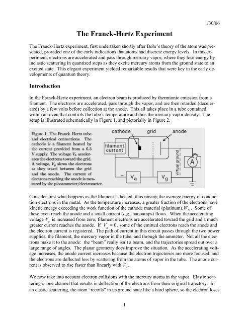
<strong>The</strong> <strong>Franck</strong>-<strong>Hertz</strong> <strong>Experiment</strong>1/30/06<strong>The</strong> <strong>Franck</strong>-<strong>Hertz</strong> experiment, first undertaken shortly after Bohr’s theory of the atom was presented,provided one of the early indications that atoms had discrete energy levels. In this experiment,electrons are accelerated and pass through mercury vapor, where they lose energy byinelastic scattering in quantized steps as they excite mercury atoms from the ground state to anexcited state. This elegant experiment yielded remarkable results that were key in the early developmentsof quantum theory.IntroductionIn the <strong>Franck</strong>-<strong>Hertz</strong> experiment, an electron beam is produced by thermionic emission from afilament. <strong>The</strong> electrons are accelerated, pass through the vapor, and are then retarded (decelerated)by a few volts before collection at the anode. This all takes place in a tube containedwithin an oven that controls the tube’s temperature and thus the mercury vapor density. <strong>The</strong>setup is illustrated schematically in Figure 1, and pictorially in Figure 2.Consider first what happens as the filament is heated, thus raising the average energy of conductionelectrons in the metal. As the temperature increases, a greater fraction of the electrons havekinetic energy exceeding the work function of the cathode material (platinum),W Pt. Some ofthese even reach the anode and a small current (e.g., nanoamps) flows. When the acceleratingvoltage V ais increased from zero, filament electrons are accelerated toward the grid and a muchgreater current reaches the anode. If V g= 0 , some of the emitted electrons reach the anode andthe electron current is registered. <strong>The</strong> path of current in this circuit passes through the two powersupplies, the filament, the mercury vapor in the tube, and through the ammeter. Not all the electronsmake it to the anode: the “beam” really isn’t a beam, and the trajectories spread out over alarge range of angles. <strong>The</strong> planar geometry does improve the situation. As the accelerating voltageincreases, the anode current increases because the electron trajectories are more focused, andthe electrons are deflected less by scattering from the atoms of vapor in the tube. <strong>The</strong> anode currentis observed to rise faster than linearly with V a.We now take into account electron collisions with the mercury atoms in the vapor. Elastic scatteringis one channel that results in deflection of the electrons from their original trajectory. Inan elastic scattering, the atom “recoils” in its ground state like a hard sphere, so the electron loses1
<strong>The</strong> Apparatus1/30/06<strong>The</strong> <strong>Franck</strong>-<strong>Hertz</strong> tube is contained within an oven, which is a metal box with a thermostaticallycontrolled heater and terminals for connections to the tube. A thermometer can be insertedthrough a hole in the top of the oven.<strong>The</strong> tube has a parallel system of electrodes in order to produce a fairly uniform electric field.<strong>The</strong> distance between the filament/cathode and the perforated grid is much larger than the meanfree path of electrons through the mercury vapor under normal operating conditions. A platinumribbon with a small barium-oxide spot serves as a direct heated cathode. An electrode connectedwith the cathode limits the current and suppresses secondary and reflected electrons, making theelectric field more uniform. In order to avoid current leakage along the hot glass wall of thetube, a protective ceramic ring is fused in the glass as a feed-through to the counter electrode.<strong>The</strong> tube is evacuated and coated inside with a “getter” which absorbs traces of air that leaked induring the manufacturing process and over the lifetime of the tube.Power supplies are provided for the accelerating and grid voltages, and a separate supply is providedfor the filament current. <strong>The</strong> anode current should be read with either a Keithley model610 Electrometer or a picoammeter. Other voltages should be monitored with DVMs.Before making any connections, be sure you understand the circuit. To aid in understanding,trace the closed circuit that electrons take from the cathodes through the power supplies and electrometerand back to the cathode. (Also see the first question.)Take care in making the connections that the signal cable is grounded correctly. <strong>The</strong> “virtualground” represents the effective electrical potential of the ammeter in the circuit. <strong>The</strong> ammeterhas a low impedance, and all the anode current flows through it.You’ll discover that the apparatus seems very sensitive to your presence! This is because thesmall currents detected represent very small amounts of charge flowing, amounts of charge thatcan be significantly affected by stray capacitance including your own, which is about 100 pf.Getting StartedWe use a <strong>Franck</strong>-<strong>Hertz</strong> tube and control unit pictured in the figure below. First take data varyingthe voltage manually with the toggle switch set to “Man”, and don’t hook up the oscilloscope.You should begin by familiarizing yourself with the apparatus, its operation, and the nature ofelectron emission from the filament. As you hook up wires, make sure you understand the circuitthrough which currents flow by tracing the path of electrons from the filament through the3
1/30/06Figure 2 – <strong>Experiment</strong>al setup with oscilloscope.wires, ammeter, etc. Do not apply voltages with the tube cold, because mercury may have condensedon the electrodes and could short out and damage parts of the tube. Start by hooking upthe filament current supply and the accelerating voltage. Connect the ammeter to the anode/collector,and use a jumper wire to short out the grid-anode gap (i.e.,V g= 0 ). It’s useful toset the ammeter so that it can measure positive or negative current; for example, set the meter toread “center zero.” Start withV a= 0 , and turn up the filament current until you see a dim orangeglow in the tube. Observe the anode current as you vary the filament current. What’s happening?With the filament current set to produce a visible orange glow—not a bright blue-white glow—begin to increase V ato about 40–60 V. Note (record) the current collected on the anode as afunction of accelerating voltage. You can do this as a function of the filament current. Be carefulthat the tube does not go into continuous discharge mode, characterized by the bright bluewhiteglow. It if does, lower the accelerating voltage 10 V or more so that it stops.<strong>The</strong> vapor pressure of mercury is a strong function of temperature; it is given by the Clausius-Clapeyron equation and tabulated in the CRC handbook. <strong>The</strong> temperature of the cabinet shouldbe adjusted to 180ºC ± 5ºC. It takes about 20 minutes to reach equilibrium after the temperaturesetting is changed. Set the sensitivity of the measuring amplifier at 10 !9 A, the retarding potentialat 1.5 V and raise the acceleration potential to 50 volts. Now, slowly increase the current inthe cathode until the ammeter reads 10 !9 A. Run the accelerating voltage down to about 15 Vand then bring it back up slowly, checking that the ammeter does not go off scale. If it does,lower the filament and repeat. <strong>The</strong> filament will respond very slowly to any changes, so allow atleast 30 seconds for it to stabilize before making new measurements.At this stage, the apparatus is ready for taking measurements. Experience shows that it’s best tostart at the highest accelerating voltage and take measurements with decreasing V avoltages. Increase(or decrease) V avery slowly. It may be helpful to change the ammeter scale for lowervoltage readings.4
1/30/06Things to measure<strong>The</strong> measurements are straightforward: anode current vs. accelerating voltage. You will findthat the apparatus is quite sensitive to your own capacitance. If you move near the set up, thecurrent changes, sometimes wildly. You will need to learn where to stand or sit so that this effectis minimized.Once you have taken the data, a plot of current vs. voltage will reveal both the rise of anode currentwith voltage and the dips corresponding to the inelastic scattering resonances. You willneed to determine the positions of the resonances. This is a challenging analysis problem sincewhat you have are dips on a changing background. You should try to fit the data to a reasonablemodel—for example, the exponentially rising emission with the observed number of (negative)gaussian dips with width and centroid as free parameters. What free parameters characterize therising exponential?<strong>The</strong> contact potential is the difference between the work functions of the cathode and anote,since they are oppositely directed in the electric field, that is, the electric field has to workagainst the cathode potential but is helped in the case of the anode. Thus we should expect thatthe voltage to the first peak will be greater than the average peak to peak voltage, due to the contactpotential. <strong>The</strong> contact potential can be calculated as the average peak to peak voltage subtractedfrom the first peak voltage.If a neon tube is available, repeat for neon.Questions1. Students often have trouble understanding the electrons’ path through the circuit that includesthe tube, and expect charge to build up at various places. Charge build-up in fact doesoccur, but not much. To make this clear, estimate the capacitance of the tube and the magnitudeof charge build-up. Compare this to the amount of current that flows around the closed circuitduring a measurement.2. <strong>The</strong> mean free path of electrons propagating in a gas is given by! "1 = # nwhere ! is the total cross section summed for all processes, elastic and inelastic, and n is thenumber density of the mercury. <strong>The</strong> number density can be found using the tables for mercuryvapor pressure in the CRC handbook. Assume that the elastic scattering cross section is the areaof a disk with the radius of a mercury atom. Find the mean free path and t 1/ 2for the vapor at180ºC. Compare this to the size of the <strong>Franck</strong>-<strong>Hertz</strong> tube, and explain what is different in thecase of elastic scattering.3. Why is the retarding voltage needed to observe the <strong>Franck</strong>-<strong>Hertz</strong> effect?4. Should you use the positions of the peaks or of the valleys to determine the excitation en-5
ergy? Or both? Explain.5. Why are the peaks and valleys smeared out rather than sharp?1/30/066. How would increasing the temperature affect your observations? Would there be a higheror lower background current? Sharper or less sharp peaks? More peaks?7. How would molecular contaminants in the tube affect your results?8. Look up the spectrum for mercury to see if there is a spectral line(or lines) whose wavelength(energy)corresponds to the energy differences you measured for mercury.6