An Oil to Water Conversion of a Hydro Turbine ... - Thordon Bearings
An Oil to Water Conversion of a Hydro Turbine ... - Thordon Bearings
An Oil to Water Conversion of a Hydro Turbine ... - Thordon Bearings
- No tags were found...

Create successful ePaper yourself
Turn your PDF publications into a flip-book with our unique Google optimized e-Paper software.
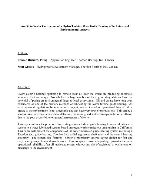
<strong>An</strong> <strong>Oil</strong> <strong>to</strong> <strong>Water</strong> <strong>Conversion</strong> <strong>of</strong> a <strong>Hydro</strong> <strong>Turbine</strong> Main Guide Bearing – Technical andEnvironmental AspectsAuthors:Conrad Richard, P.Eng – Application Engineer, <strong>Thordon</strong> <strong>Bearings</strong> Inc., Canada.Scott Groves – <strong>Hydro</strong>power Development Manager, <strong>Thordon</strong> <strong>Bearings</strong> Inc., CanadaAbstract:<strong>Hydro</strong>-electric turbines operating in remote areas all over the world are producing enormousamounts <strong>of</strong> clean energy. Nonetheless, a large number <strong>of</strong> these generating stations have thepotential <strong>of</strong> posing an environmental threat <strong>to</strong> local ecosystems. <strong>Oil</strong> and grease have long beenconsidered as one <strong>of</strong> the primary methods <strong>of</strong> lubricating the lower turbine guide bearing. Asenvironmental regulations become more stringent, any accidental or operational loss <strong>of</strong> oil orgrease <strong>to</strong> the environment is not acceptable and can have very grave repercussions. This can be aserious issue in remote areas where detection, moni<strong>to</strong>ring and spill clean-up can be very difficultdue <strong>to</strong> the poor accessibility or general remoteness <strong>of</strong> the site.This paper outlines the process <strong>of</strong> converting a lower turbine guide bearing from an oil lubricatedsystem <strong>to</strong> a water lubricated system, based on recent works carried out on a turbine in California.This paper will present the components <strong>of</strong> the water lubricated guide bearing system including a<strong>Thordon</strong> SXL guide bearing, <strong>Thordon</strong> SXL radial segmented shaft seals and the overall housingassembly. The system also features <strong>Thordon</strong>’s proprietary tapered keyset design for fast andeasy bearing inspection and maintenance. This complete conversion package provides the sameoperational reliability <strong>of</strong> an oil lubricated system without any risk <strong>of</strong> accidental or operational oildischarge <strong>to</strong> the environment.1
His<strong>to</strong>rical:In mid-2009, initial conversations began with an important electricity producer on the west coas<strong>to</strong>f the U.S. on the subject <strong>of</strong> converting an oil lubricated turbine main guide bearing <strong>to</strong> a waterlubricated bearing system. The first unit considered for such a project was located in themountains using run<strong>of</strong>f from a lake at a higher elevation <strong>to</strong> generate electricity. This particularunit was originally built in 1927 and is the first <strong>of</strong> two power houses connected in series. Fac<strong>to</strong>rsconsidered in the selection <strong>of</strong> the first conversion site were the age <strong>of</strong> the unit and ease <strong>of</strong> access<strong>to</strong> the power house. The chosen unit is the older <strong>of</strong> the two and was determined <strong>to</strong> be thegreatest risk for oil leakage which would have devastating effects on the complete eco-systemdownstream <strong>of</strong> the station. It is also the more accessible <strong>of</strong> the two units at this particular site.The original installation had the following equipment:• <strong>Oil</strong> lubricated metal bearing• Cast steel split carrier• Closed loop oil lubrication system with: oil sump system, oil pump, oildistribution piping and oil condition moni<strong>to</strong>ring• Upper seal and seal housing• Separate stuffing box <strong>to</strong> keep the water and the oil separate.Figure 1: Original Spare White Metal Bearing & Carrier.In early 2010, conceptual designs were developed for the cus<strong>to</strong>mer. Initial concepts weredeveloped for two options.Option 1 was a complete new carrier and bearing assembly that included the following items:<strong>Water</strong> lubricated split <strong>Thordon</strong> SXL bearing with bronze tapered keysetFabricated split steel carrier2
<strong>Oil</strong> Distributionand Upper Seal& HousingOriginal <strong>Oil</strong>LubricatedMetal Bearing &Cast CarrierStuffing Box& PackingFigure 2: Cross Section <strong>of</strong> Original <strong>Turbine</strong> Assembly<strong>Thordon</strong> SXL segmented shaft seals with <strong>Thordon</strong> Regular backing ringsSplit steel seal housingSeal bypass water catch basin with drain pipeDischarge water ductDesign features <strong>to</strong> accommodate an open system <strong>of</strong> water flow for cooling andlubricationStainless steel shaft sleeve.3
Option 2 was similar <strong>to</strong> option 1 except a spare bearing carrier would be used that was already onsite. The spare carrier was <strong>to</strong> be modified <strong>to</strong> accept a new water lubricated bearing, newsegmented seals and discharge duct. There was some uncertainty regarding the feasibility <strong>of</strong>reusing an original carrier due <strong>to</strong> oil holes in the casting and possible weakening <strong>of</strong> the structureafter the ID had been bored <strong>to</strong> accept the new bearing.The final solution that was recommended and chosen by the cus<strong>to</strong>mer was option 1. This optiongave the cus<strong>to</strong>mer the least amount <strong>of</strong> unknown variables. Option 1 also had the added benefit(in the cus<strong>to</strong>mer’s eyes) that the original spare carrier was still available for use as plan “B”.With final option 1 chosen and ordered, the design was finalized and production began in latespring 2010. The completed order was supplied in late August and installed during a plannedshutdown in Oc<strong>to</strong>ber 2010.Design Features:<strong>Thordon</strong> SXL <strong>Water</strong> Lubricated Bearing:<strong>Water</strong> lubricated <strong>Thordon</strong> SXL bearings have a proven track record as main guide bearings inhydro turbines. <strong>Thordon</strong> SXL is an elas<strong>to</strong>meric polymer material <strong>of</strong>fering the combination <strong>of</strong>strength/stiffness and flexibility/elasticity. <strong>Thordon</strong> <strong>Bearings</strong> has supplied many such bearingsas replacements for other non-metallic bearings. Experience has shown that <strong>Thordon</strong> SXLbearings have an excellent wear life and they perform very well in such applications. The<strong>Thordon</strong> SXL main guide bearing is designed with clearances and a groove arrangement suitedfor the application. Running clearances for <strong>Thordon</strong> SXL main guide bearings are driven by theshaft diameter and generally reduce at a rate <strong>of</strong> approximately 0.0002” per inch <strong>of</strong> shaftdiameter, from a maximum .012” for a 47” diameter shaft. The design also considers the amoun<strong>to</strong>f water absorption, thermal expansion and bore closure due <strong>to</strong> the interference fit. The selecteddesign was for a shaft over liner diameter <strong>of</strong> 14.75” and housing inside diameter <strong>of</strong> 16.94”. Theinstalled and running clearances were .023” & .006” respectively. A <strong>to</strong>tal allowance <strong>of</strong> .017” isincluded <strong>to</strong> compensate for water absorption and thermal expansion. <strong>Water</strong> absorption willoccur during a certain period <strong>of</strong> time that typically ranges from 2-3 months. However thespecific water absorption rate is also dependent on the temperature.Fabricated Split Steel Carrier:In order <strong>to</strong> facilitate the conversion process; a cus<strong>to</strong>m carrier was designed <strong>to</strong> interface with theexisting register fits and mounting features in the head cover. The carrier was <strong>of</strong>fabricated/welded designed and was split so the unit could be installed in position withoutrequiring the removal <strong>of</strong> the shaft.Bronze Tapered Keyset:A tapered keyset is included in the package. The <strong>Thordon</strong> Bearing’s proprietary split taperedkey design not only provides anti-rotation retention but it also allows for easy removal <strong>of</strong> thebearing for replacement or inspection without removing the shaft or the carrier. The key is made4
from bronze, not only for corrosion resistance but also for ease <strong>of</strong> disassembly. In many cases abearing inspection or replacement can be done in a matter <strong>of</strong> hours instead <strong>of</strong> days or weeks.<strong>Thordon</strong> SXL Segmented Shaft Seals and <strong>Thordon</strong> Regular Backing Rings:As is the case for <strong>Thordon</strong> SXL main guide bearings, the <strong>Thordon</strong> SXL polymer also has aproven track record used as a segmented shaft seal. <strong>Thordon</strong> SXL is being used <strong>to</strong> replace othernon-metallic segmented seals in many applications throughout the world. <strong>An</strong>other <strong>Thordon</strong>grade, Regular, is used as backing plates. Cus<strong>to</strong>m garter springs are also included <strong>to</strong> maintain thestatic and dynamic contacts <strong>of</strong> the segmented seal segments.Figure 3: Complete Unit as Designed, Mock‐up and As Installed <strong>of</strong> Option 1Split Steel Seal Housing:Each layer <strong>of</strong> the segmented seal arrangement is contained in a cus<strong>to</strong>m designed seal housing.The completed seal housing assembly is designed <strong>to</strong> be mounted directly on<strong>to</strong> the <strong>to</strong>p flange <strong>of</strong>the bearing carrier. The seal housing assembly has connections for water injection for coolingand lubrication <strong>of</strong> the seals and also the bearing. The arrangement is designed as a two ringsegmented seal assembly with the two rings above the water inlet and the bearing below.Seal Bypass <strong>Water</strong> Catch Basin with Drain Pipe:In order for segmented shaft seals <strong>to</strong> function properly and not overheat, cooling water must leakpast the dynamic sealing faces. The geometry and the interface between the seal segments, thehousing and the dynamic shaft interface are designed <strong>to</strong> allow water <strong>to</strong> flow past the seals andtherefore this water needs <strong>to</strong> be collected. After the water flows through the seals it is collectedin the <strong>to</strong>p basin. It then flows out through the drain pipe <strong>to</strong> the discharge water duct below thebearing.5
Discharge <strong>Water</strong> Duct:There was an area between the bot<strong>to</strong>m <strong>of</strong> the bearing/carrier and the existing stuffing box wherethe shaft was exposed. Because the new system is an open system where the cooling water is fedfrom the pens<strong>to</strong>ck supply and not re-circulated, after the water has passed through the bearingand/or the seals, it has <strong>to</strong> be disposed <strong>of</strong>. By including a discharge duct that connects directly <strong>to</strong>the bot<strong>to</strong>m <strong>of</strong> the new carrier <strong>to</strong> divert the water <strong>to</strong> the existing stuffing box, the water is simplyreintroduced <strong>to</strong> the pens<strong>to</strong>ck water. With the original packing and lantern ring removed, watercan flow freely through the stuffing box. A small gasket is installed between the ID <strong>of</strong> thestuffing box and the OD <strong>of</strong> the discharge duct <strong>to</strong> s<strong>to</strong>p any splashing. Due <strong>to</strong> the vacuumconditions at the head cover and the elevation <strong>of</strong> the powerhouse on the mountain there is noconcern about back pressure and a possible flood. The discharge duct also has a connection forthe drain pipe from the seal bypass water catch basin.Bypass <strong>Water</strong>Catch BasinSegmentedSeals, BackingRings & GarterDrain PipeTapered Key2x <strong>Water</strong>InletsFabricatedSplit SteelCarrierSXL GuideBearingDischarge <strong>Water</strong>Duct withConnection <strong>to</strong> DrainFigure 4: Section <strong>of</strong> Assembled Supplied Parts6
Stainless Steel Shaft Sleeve:With the original bearing operating with oil lubrication there were no problems from corrosion <strong>of</strong>the carbon steel shaft. However with water lubrication, corrosion <strong>to</strong> the shaft is a concern. If theshaft begins <strong>to</strong> corrode in way <strong>of</strong> the bearing or the segmented seals, the corrosion couldaccelerate the wear <strong>of</strong> the <strong>Thordon</strong> SXL components. A new stainless steel liner was installedon<strong>to</strong> the shaft in way <strong>of</strong> the bearing and segmented seals. The liner was supplied as split andwelded <strong>to</strong>gether on site. The OD <strong>of</strong> the liner was final machined in place <strong>to</strong> a predetermineddimension.Operating Conditions:The bearing was designed <strong>to</strong> operate on the following unit, under the listed conditions:ManufacturerPel<strong>to</strong>n <strong>Water</strong> WheelYear Built 1927TypeVertical, FrancisRunner Diameter 5’‐10”Horsepower 13,750Rated Flow (cfs) 550Gross Head (ft) 197Speed (rpm) 257Shaft Sleeve Outside Diameter (in) 14.75The cus<strong>to</strong>mer also knew that the head cover was normally in a partial vacuum condition but fullinformation was not available at the time <strong>to</strong> indicate the exact amount. Packing from the existingstuffing box had long since been removed and not replaced. However due <strong>to</strong> powerhouselocation, partway up a mountain, there was no major concern <strong>of</strong> backflow in<strong>to</strong> the powerhouse.When installation was complete and the turbine was restarted, it was noticed that even at therecommended water flow, there was no water leakage past the seals in<strong>to</strong> the collection basin. Itwas at this time that the vacuum issue became apparent. The initial reaction was <strong>to</strong> increase thewater flow <strong>to</strong> as much as 50% above the recommended value but this still did not correct theproblem. As a temporary measure, it was recommended that a secondary water supply beprovided <strong>to</strong> the basin in order <strong>to</strong> reverse flow through the segmented seals for cooling and <strong>to</strong>avoid overheating.Some flow and friction loss calculations determined that the void in front <strong>of</strong> the tapered keysetwas almost equivalent <strong>to</strong> all the other bearing grooves added <strong>to</strong>gether. Several options wereconsidered <strong>to</strong> cure this problem. A possible design feature <strong>to</strong> ensure the bearing and the sealswere continuously flooded was <strong>to</strong> add a restric<strong>to</strong>r ring under the bearing. This option wasconsidered and evaluated as a possible solution. Different materials were also considered for useas the restric<strong>to</strong>r ring. The downside <strong>of</strong> this option was that very high pressures are required <strong>to</strong>ensure the required amount <strong>of</strong> water flow through the typically tight clearance <strong>of</strong> such rings. Theminimum recommended water flow for <strong>Thordon</strong> polymer bearing materials in a main guideapplication with similar clearances is 2gallons per minute per inch <strong>of</strong> shaft diameter. In thisparticular application the minimum recommended flow rate was ~30gallons per minute. After7
much discussion and deliberation, the proposed fix was a spacer that would fill most <strong>of</strong> the voidin way <strong>of</strong> the keyset. The cus<strong>to</strong>mer agreed <strong>to</strong> implement this solution at their next scheduledshut down occurring in a few months. In order <strong>to</strong> facilitate the installation <strong>of</strong> the spacer, a newsliding key was machined and the spacer was attached <strong>to</strong> it. This allowed the new spacer <strong>to</strong> beinstalled by simply removing the sliding section <strong>of</strong> the original keyset and replacing with thenew key/spacer assembly.Figure 5: Installation without and with spacer.Since start-up <strong>of</strong> the water lubricated system, the unit was moni<strong>to</strong>red actively and no other issueswere identified. The SXL bearing was operating smoothly and not showing any signs <strong>of</strong>overheating or other malfunction. The cus<strong>to</strong>mer even requested the opinion <strong>of</strong> <strong>Thordon</strong> <strong>Bearings</strong>on a possible delay the planned shutdown for several more months until the end <strong>of</strong> the springrun<strong>of</strong>f. It was determined that if all else was operating smoothly, that there should be no issuewith a delayed shutdown provided the bearing operation was moni<strong>to</strong>red.Eventually in May 2011, the unit was put <strong>of</strong>fline and the bearing and seals were removed,inspected and reinstalled along with the new spacer. Prior <strong>to</strong> removal <strong>of</strong> the components, therewere some concerns <strong>of</strong> a possible overheating <strong>of</strong> the installed components, but after inspection,8
pressure balance in the system from the cooling water injection <strong>to</strong> the area where the water exitsthe bearing. The friction loss through the bearing clearance and through the grooves iscalculated using the Hazen–Williams Equation for Pressure Loss in Pipes. The groove amountand decision on the design (or need) for a spacer in way <strong>of</strong> the tapered key is based on arequirement <strong>to</strong> have sufficient water pressure above the bearing <strong>to</strong> split the water flow. Themajority <strong>of</strong> the water flows through the bearing but some is also diverted up through thesegmented seals. Even in the presence <strong>of</strong> a partial vacuum, seals are still required <strong>to</strong> ensure thatthe proper amount <strong>of</strong> cooling water is directed through the bearing.As expected, calculations on further projects have shown that the void in way <strong>of</strong> the key is more<strong>of</strong> a fac<strong>to</strong>r on units with small <strong>to</strong> medium size shafts (less than 16” - 18” diameter). On unitswith larger shafts (greater than 30” diameter), the number <strong>of</strong> grooves in the bearing is such thatthe void in way <strong>of</strong> the grooves is large enough that the void at the key is no longer such animportant contribu<strong>to</strong>r <strong>to</strong> the flow area.The requirement for minimum flow is also dependant on the shaft diameter and increases by afac<strong>to</strong>r <strong>of</strong> 2 for each increment in shaft diameter. Therefore, units with large shafts require muchmore water flow compared <strong>to</strong> smaller units. The higher water flow results in greater friction losseven without a spacer in way <strong>of</strong> the key. Each proposal has <strong>to</strong> be evaluated on a case by casebasis.Conclusion:With the large amount <strong>of</strong> hydro turbines in operation all over the world and with many <strong>of</strong> thembeing multiple decades old, the risk <strong>of</strong> operational oil leaks is a big concern. Many generatingstations are located in remote locations and others are in close proximity <strong>to</strong> environmentallysensitive areas. Not <strong>to</strong> mention that contaminated water streams can have adverse effects onecosystems and watersheds many miles downstream.With environmental policies and legislations at every level <strong>of</strong> government becoming morestringent, the potential environmental and financial costs <strong>of</strong> an oil leak are causing many energyproducers <strong>to</strong> seriously consider water lubrication over conventional oil systems; either forconversions or for new construction projects.To eliminate any risk <strong>of</strong> oil leakage, <strong>Thordon</strong> <strong>Bearings</strong> can prepare cus<strong>to</strong>m designed solutions <strong>of</strong>water lubricated lower guide bearings. Solutions can range from a simple bearing supply <strong>to</strong> acomplete bearing / carrier / segmented seal assembly conversion package. Working with hydroelectricturbine opera<strong>to</strong>rs around the world, <strong>Thordon</strong> <strong>Bearings</strong> is not just providing bearings <strong>to</strong> fitan application, but developing bearing solutions <strong>to</strong> resolve and overcome bearing applicationchallenges.<strong>Thordon</strong> <strong>Bearings</strong> has long been at the forefront <strong>of</strong> providing premium bearing material for waterlubricated applications. With this hydro-turbine example and other current oil <strong>to</strong> waterconversions, <strong>Thordon</strong> is quickly becoming an experienced global provider <strong>of</strong> cus<strong>to</strong>m engineeredsolutions that remove all the risks <strong>of</strong> oil loss <strong>to</strong> the environment.10
Author Biographies:Conrad Richard, P.Eng is an Application Engineer at <strong>Thordon</strong> <strong>Bearings</strong> Inc. Conrad completedhis Bachelor Degree in Mechanical Engineering at the Université de Monc<strong>to</strong>n, in 1997 and hasworked in several different industries ranging from mining <strong>to</strong> machine design for the opticalindustry before joining <strong>Thordon</strong> in 2009.Scott Groves started his career at <strong>Thordon</strong> <strong>Bearings</strong> in March <strong>of</strong> 2002 in the commercialdepartment, assuming the role <strong>of</strong> sales manager in Canada and the Western US in 2003. Scottwas appointed <strong>Thordon</strong> Bearing’ global hydro business development manager in 2011. Scotthas extensive experience with operating mechanism bearing conversions as well as turbine guidebearing oil <strong>to</strong> water conversion.11