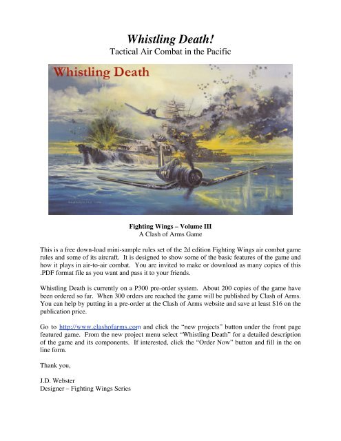
Whistling Death! - Clash of Arms
Whistling Death! - Clash of Arms
Whistling Death! - Clash of Arms
- No tags were found...

You also want an ePaper? Increase the reach of your titles
YUMPU automatically turns print PDFs into web optimized ePapers that Google loves.
INITIATIVE ROLL Initiative Mod: Veteran +1 Regular +0 Green –2 Recruit –4START HEX Keen eyes: +02 to Tac-scale first sight rolls if a flight leadSTART FACING Ace / Hero: –05 to attack LH rolls for eachSTART ALTITUDE Crack shot: + or –1 to critical hit area roll if range 2 or lessSTART SPEED Gifted Flyer: HT+ turns or transitions at .05 speed less0.5 FP CARRY Station: Item Load WeightDECEL CARRY Wpn. Group Ammo Shots FiredACCEL – DECEL = Endurance Available:NET SPEED CHANGE Endurance Used/Lost:________________________AIRCRAFT:FW – A/C FLIGHT LOG SHEETGAME TURN 1 2 3 4 5 6 7 8 9 10 11 12 13 14 15 Next Log Pilot:ANGLE-OF-BANKTURN / MNVR. CARRYSTART FLT. ATT.TRANS. RATE - STEPSHFP / VFP SPLIT/ / / / / / / / / / / / / / / /MAND. ALT. CHANGE Hits Taken:VFP ALT. CHANGEOPT. ALT. CHANGENET ALTITUDE CHANGETHROTTLE Damage Notes:ACCEL CARRYPOWER ACCELDIVE & DV. ATT. ACCELTOTAL ACCELTRANSITION DECELCLIMB & CL. ATT. DECELINVERTED & MISC. DEC.TURN RATE DECELMANEUVER DECELOVERSPEED DECELTOTAL DECEL______________________________
A/C TURN CHART (Banking - A/C must be in LB or ILB to turn left, RB or IRB to turn right)A/C SPEED EASY TIGHT HARD BREAK EMERG. SCALEin FPs "EZ" "TT" "HT" "BT" "ET" MPH1.0 - 1.5 1 60 90 NA NA 50 - 752.0 - 2.5 2 1 60 90 NA 100 - 1253.0 - 3.5 3 2 1 60 90 150 - 1754.0 - 4.5 4 3 2 1 60 200 - 2255.0 - 5.5 6 4 3–2 2–1 1 250 - 2756.0 - 6.5 8 6 3 2 2–1 300 - 3257.0 - 7.5 10 7 4 3–2 2 350 - 3758.0 - 8.5 12 8 5 3 3–2 400 - 4259.0 - 9.5 15 9 6 4 3 450 - 47510.0 - 10.5 18 10 8 5 3 500 - 52511.0 - 11.5 22 12 9 6 4 550 - 57512.0 - 12.5 26 14 11 7 5 600 - 6251. Procedure - Cross index speed with turn rate to find the minimum turning FPs required per 30°<strong>of</strong> facing change. Turn Rate decel is incurred per 30° <strong>of</strong> facing change.2. "90" or "60" entries indicate a maximum allowed facing change in degrees for one FP.4. “3-2” or “2-1” entries indicate a split turning FP requirement; the left no. for the first facing changeand the right no. is for the next facing change. The cycle repeats for a continuous turn at that rate.FLIGHT PROCEDURES SUMMARYFRACTIONAL VALUESNo. 1/4 1/3 1/2 2/30.5 0.0 0.0 0.0 0.51.0 0.0 0.5 0.5 0.51.5 0.5 0.5 0.5 1.02.0 0.5 0.5 1.0 1.02.5 0.5 1.0 1.0 1.53.0 0.5 1.0 1.5 2.03.5 1.0 1.0 1.5 2.54.0 1.0 1.5 2.0 2.54.5 1.0 1.5 2.0 3.05.0 1.0 1.5 2.5 3.55.5 1.5 2.0 2.5 3.56.0 1.5 2.0 3.0 4.06.5 1.5 2.0 3.0 4.57.0 1.5 2.5 3.5 4.57.5 2.0 2.5 3.5 5.08.0 2.0 2.5 4.0 5.58.5 2.0 3.0 4.0 5.59.0 2.0 3.0 4.5 6.09.5 2.5 3.0 4.5 6.510.0 2.5 3.5 5.0 6.510.5 2.5 3.5 5.0 7.011.0 2.5 3.5 5.5 7.511.5 3.0 4.0 5.5 7.512.0 3.0 4.0 6.0 8.0A. Use throttle: Take from 0 to highest number shown on Powerversus Speed Chart for A/C’s speed range and altitude.B. If Stalled: A/C has zero FPs, and will lose altitude in increments= to listed minimum speed plus number <strong>of</strong> game turns stalled. Flight Att.= STD. Dive and engine accel are added normally. When start speed> minimum speed, A/C may fly again. If A/C hits altitude 0.0 it crashes.C. Choose Flight Attitude: Remain in same attitude, or transition tonew attitude. If transition desired, find A/C's start attitude, select turnrate used for pull or push transition and count around Flight AttitudeDiagram a number <strong>of</strong> attitudes allowed by turn rate to find ending flightattitude. Use average flight path for determining VFPs allowed.D. Execute A/C Move: Proceed as follows:• Apply any mandatory altitude change (MC) immediately.• Expend FPs in compliance with Flight Proportion restrictions<strong>of</strong> average attitude. (HFPs & VFPs may be mixed in any order)• Take optional altitude change (OC) at end <strong>of</strong> move if desired.• Each VFP expended changes altitude by 300 feet.• If A/C transitions through a vertical attitude, or ends in a verticalatt. and reverses bank angle, perform a flight direction reversalat end <strong>of</strong> its move.E. Determine Speed Change: Record accel & decel points incurred.Subtract decel from accel. A/C gains or loses 0.5 speed per 5 accelor decel left. Record on flight log - A/C's new attitude, altitude,speed, bank angle and any 0.5 FP, accel or decel carried forward.FLIGHT PROPORTIONS TABLEFlight Mandatory VFPs Allowed OptionalAttitude Changes (Rest are HFPs) ChangesLevel None None ± up to 1/4 +Shallow 1/3 + 0 or 1 FP as VFP up to 1/3 –Steep 1/2 + 1 to ≤ 1/2 <strong>of</strong> speed up to 1/2 –Vertical 1/3 + > 1/2 to All <strong>of</strong> speed up to 1/3 –Notes:1. Fractions indicate change in alt. increments = to that portion<strong>of</strong> A/C's speed ("+" = round up fraction, "–" = round down).2. Mandatory changes (MC) are based on starting flight attitude.3. VFPs allowed are based on average flight attitude.4. Optional changes (OC) are based on ending flight attitude.5. Fractional values Table procedure - If start attitude is:• Level or shallow, round VFP portion down, HFP portion up.• Steep or vertical, round VFP portion up, HFP portion down.(VC)VC(STC)STCVD(VD)Flight Attitudes DiagramTransition Turn Rate = Flight Attitude ChangesNone = 0 EZ = 1 TT = 1 HT = 2 BT = 3 ET = 4• If pulling or pushing with gravity at start, +1 change allowed.• Pushing more than two steps invokes Neg. G shot modifiers.• Outer circle shows flight att. changes when pulling nose up.• Inner circle shows flight att. changes when pushing nose down.• For TT or higher transitions, Average flight path (AFP) = flightattitude half way between original and new attitude (rounded up).• If using EZ transition, AFP is same as start flight attitude.• Decel for transitioning = decel for turn rate used x no. <strong>of</strong> changes.(SHC)STD(STD)SHCSHD(SHD)(INV)LVLWithGravityAgainstGravity(INV)LVLSHCFlight DirectionReversal Area(SHD)(SHC)HALF FPs RULESTCVC(STC)SHD(VC)(STD)STD(VD)VDWhen 0.5 FP carry mates with half speed to create a bonus FP:• If start attitude is level or shallow, bonus FP must be HFP.• If start attitude is steep or vertical, bonus FP must be VFP.
AIR-TO-AIR COMBAT PROCEDURE1. Determine Range <strong>of</strong> attack = Hexes + each 300 feet.Add up firepower <strong>of</strong> all weapons fired at that range.2. Determine deflection angle.a. Get defense multiplier from heading differenceb. +1 to mult. if target or shooter in level & other not.c. +2 if target or shooter is diving and other climbing.3. Multiply target defense strength by multiplier. Getcombat odds by dividing firepower by final defense str.4. Roll percentile dice on odds table to determine no.<strong>of</strong> hits acheived. For each multiple <strong>of</strong> hits equal togun groups critical rating, inflict one critical hit.5. Roll d10 to determine where critical hits occur ontable below, roll d10 for critical effect in each area.Apply any modifiers for A/C protection to effect rolls.Quick Start - Fighting Wings Combat Tables120° X690° X5(3:00L)180° X3(12:00L)150° X4 150° X4120° X690° X5(9:00L)A/C CRITICAL AREA HIT TABLE (D10)D10 Area Hit D10 Area Hit≤ 2 Engine (random which) 6 Cockpit3, 4 Fuel tanks 7, 8 Wings5 Hollow space (no effect) ≥ 9 ControlsModifiers: –1 if final deflection to target = 150 or 180.+1 if final deflection to target = 30 or 00. –1 if multi-engine A/C.–1 if hit from 12:00 line. Crack shots may adjust ±1 if range ≤ 2.CRITICAL HIT EFFECTS TABLE (D10)60° X330° X2Area Hit 1 or less 2 to 3 4 to 6 7 to 8 9 or moreEngine: Eng. seizes Fire! Power loss Power loss Oil LeakFuel Tanks: A/C blows up* Fire! Fuel Leak Fuel Leak Fuel LeakCockpit: 1 crew killed* 1 crew Killed* 1 crew wnd. N gun out No effectWings: Wing breaks <strong>of</strong>f* Wing spar** +1 banks / slips W gun out No effectControls Cables severed* Tail structure** +1 banks / slips +1 banks Dam. cable• (*) If all engines seized, or an asterix result occurs, A/C is destroyed.• (**) 3 wing spar or tail str. hits destroy an A/C. If wounded twice, crewman is killed.• Oil & fuel leaks and damaged cables provide -1 mod.s to subsequent rolls in that area.• Power loss reduces max accel on eng. hit by a fraction (to 2/3, 1/2, 1/3, 1/4, then eng. out).• For each fire, roll D10 end <strong>of</strong> each turn, (1= A/C blows up, 9 or 10= fire out). -1 if fuel fire.0° X1(6:00L)Shooter30° X260° X312:00 Line6:00 LineDeflection Multiplier Play AidGun Attack Percent - Die Roll ModifiersSpecial Damage Rule: If cumulative modifiers will cause a percentile roll 01 to miss, a roll <strong>of</strong> 01 will still inflict 4 hits regardless <strong>of</strong> odds.Recruit or Green pilot / crew = +30, +15 Firer used TT turn* = +00 / +10* Target size modifier = –05 x ADC modifierVeteran or hero pilot / crew = –05 each Firer used HT turn* = +10 / +20* Deflection modifiers = Var. Defense. Str.Ace or crack shot pilot = –10 each Firer used BT turn* = +20 / +30* *Turn rate mods. for F&L / M&H class resp.Firer or aimer wounded (Wnd) = +20 Gun harmony, if range 2, 3 and if ≥ half actual guns used are wing guns = –15, –10Firing A/C severely damaged = +30 Each hex past gun harmony if ≥ half actual guns used are wing guns = +10Firing A/C inverted or neg.-G = +30 If shooter’s 12:00 line superimposes target’s 6:00 line with 180, 0 deflection = –10, –20DAMAGE (Hits Achieved) TABLEPercent COMBAT ODDSDie Roll 1–6 1–4 1–2 1–1 1.5–1 2–1 3–1 4–1 5–1 6–1 8–1 10–1 12–1≤ 01* 4 4 5 6 7 8 9 10 12 14 16 18 2002 to 05 2 3 4 5 6 7 8 9 10 12 14 16 1806 to 11 1 2 3 4 5 6 7 8 9 10 12 14 1612 to 22 – 1 2 3 4 5 6 7 8 9 10 12 1423 to 39 – – 1 2 3 4 5 6 7 8 9 10 1240 to 59 – – – 1 2 3 4 5 6 7 8 9 1060 to 76 – – – – 1 2 3 5 5 6 7 8 977 to 87 – – – – – 1 3 4 5 5 6 7 888 to 93 – – – – – – 2 3 4 5 5 6 794 to 96 – – – – – – – 2 3 4 4 5 697 to 98 – – – – – – – – – – 2 4 5≥ 99 – – – – – – – – – – – – –
A/C Type:Engine(s):Eng. Pwr:A/C Crew:F4F-4 “Wildcat”Grumman Carrier Based FighterOne Pratt & Whitney R-1830-861000 - 1200 HP, Radial Air CooledPilotMax Speed: 320 MPH at 18,800 FeetMax Ceiling: 34,000 / 27,900 / 20,100 FeetDefense Factor: 5 Size Modifier: + 0Damage Factor: 9 / 13 Endurance: 200Cockpit View: Fair Blind Area: RearProtection: Cockpit +2 Fuel +2 Engine +0Climb Decel / Dive Accel: 3.0 / 1.0Weight and Load Limit: 1,070 / 2 - 5Wpn. Stations Weight Allowed Loads1, 5 110 Bomb2, 4 425 Fuel Tank3 300 Fuel TankCountry: U.S.A. Service Entry Date: December 1941Class: F Victory Points: 5 - 9AIRCRAFT PERFORMANCE CHARTAltitude Minimum Maximum Maximum Min. Min. Min. Min. Altitude AverageLevels Band Speed Speed Dive Spd. TT (2) HT (3) BT (4) ET (5) Band Levels Rate Of Climb43+ UH ––– ––– ––– –– –– –– –– UH 43+ ––––37 - 42 EH ––– ––– ––– –– –– –– –– EH 37 - 42 ––––31 - 36 VH 3.0 5.5 9.5 4.0 5.5 7.0 8.0 VH 31 - 36 30025 - 30 HI 2.5 5.5 10.0 3.5 5.0 6.0 7.0 HI 25 - 30 70019 - 24 MH 2.5 6.0 10.0 3.0 4.5 5.5 6.5 MH 19 - 24 1,40013 - 18 ML 2.0 6.0 10.0 3.0 4.0 5.0 6.0 ML 13 - 18 1,7007 - 12 LO 2.0 6.0 9.5 2.5 4.0 4.5 5.5 LO 7 - 12 1,8001 - 6 VL 1.5 5.5 9.0 2.5 3.5 4.0 5.0 VL 1 - 6 1,900FIRE POWER CHARTGuns Type Weapons Ammo CriticalsW1 One .50 Calibre M2 9 3W2 Two .50 Calibre M2 9 3W3 Two .50 Calibre M2 9 3W4 One .50 Calibre M2 9 3GUN ATTACK FACTORSRange W1 W2 W3 W4 Total0 9 18 18 9 54 / 361 7 14 14 7 42 / 282 4.5 9 9 4.5 27 / 183 3 6 6 3 18 / 124 2 4 4 2 12 / 85 1.5 3 3 1.5 9 / 66 1 2 2 1 6 / 47 –– –– –– –– –– / ––WEAPON STATIONS1 2 3 4 5POWER VERSUS SPEED CHARTLevels Band 1.0 - 4.5 5.0 - 7.5 8.0 - 9.5 10.0 + Band43+ UH ––– ––– ––– ––– UH37 - 42 EH ––– ––– ––– ––– EH31 - 36 VH 3.0 1.0 ––– ––– VH25 - 30 HI 5.0 2.0 ––– ––– HI19 - 24 MH 6.0 3.0 ––– ––– MH13 - 18 ML 7.0 4.0 ––– ––– ML7 - 12 LO 7.0 4.0 ––– ––– LO1 - 6 VL 7.0 4.0 ––– ––– VLBanking FPs: 2 2 3 5Side Slip FPs: 2 3 5 6NOTES & VARIANTSF4F-4s: Station 3 for the drop tank was a field modification done in Pearl Harborand used from July 1942 on. Stations 2 and 4 for drop tanks were incorporated intoproduction A/C delivered from October 1942 on. A/C with stations 2 and 4 did nothave station 3. Flaps can only be used at speeds ≤ min. +1.0. Above that they retractautomatically due to air pressure. They cannot be damaged by over-speed.FM-1: December 1942 General Motors 4-gun model. As F4F-4 except W2 & W3=One .50 Calibre M2. Data as for W1 & W4, ammo= 16 for all guns. Delete stations2, 3, 4. (900 built). Use Firepower Totals after slash.Martlet V: Export version <strong>of</strong> the FM-1. 312 were supplied to the British Fleet AirArm starting February 1943. Exactly as FM-1. Used in the Atlantic and Mediterraneantheaters from escort carriers.
Mitsubishi A6M2 “Zero”Country: Japan Service Entry Date: December 1940A/C Type:Engine(s):Eng. Pwr:A/C Crew:Model 21 Type 0 Carrier FighterOne Nakajima Sakae 12, No F.I.820 - 950 HP, Radial Air CooledPilotMax Speed: 331 MPH at 14,900 FeetMax Ceiling: 33,800 / 27,700 / 20,000 FeetDefense Factor: 5 Size Modifier: +0Damage Factor: 6 / 10 Endurance: 250Cockpit View: Good Blind Area: Rear lowProtection: Cockpit +0 Fuel +0 Engine +0Climb Decel / Dive Accel: 3.0 / 1.0Weight and Load Limit: 870 / 2 - 5Wpn. Stations Weight Allowed Loads1, 3 135 Bomb2 600 Fuel TankClass: F Victory Points: 4 - 8AIRCRAFT PERFORMANCE CHARTAltitude Minimum Maximum Maximum Min. Min. Min. Min. Altitude AverageLevels Band Speed Speed Dive Spd. TT (2) HT (3) BT (3) ET (4) Band Levels Rate Of Climb43+ UH ––– ––– ––– –– –– –– –– UH 43+ ––––37 - 42 EH ––– ––– ––– –– –– –– –– EH 37 - 42 ––––31 - 36 VH 2.5 5.5 9.5 3.5 5.0 6.0 7.0 VH 31 - 36 60025 - 30 HI 2.0 6.0 10.0 3.0 4.5 5.5 6.5 HI 25 - 30 1,40019 - 24 MH 2.0 6.0 10.0 3.0 4.0 5.0 5.5 MH 19 - 24 2,00013 - 18 ML 2.0 6.5 9.5 2.5 3.5 4.5 5.0 ML 13 - 18 2,4007 - 12 LO 1.5 6.0 9.0 2.5 3.5 4.0 4.5 LO 7 - 12 3,1001 - 6 VL 1.5 5.5 8.0 2.0 3.0 3.5 4.5 VL 1 - 6 3,300FIRE POWER CHARTGuns Type Weapons Ammo CriticalsN1 One 7.7mm Type 97 16 4N2 One 7.7mm Type 97 16 4W1 One 20mm Type 99m1 3.5 (6) 2W2 One 20mm Type 99m1 3.5 (6) 2GUN ATTACK FACTORSRange N1 N2 W1 W2 Total0 5 5 13 13 361 4 4 10 10 282 3 3 7 7 203 2 2 5 5 144 1 1 3 3 85 1 1 2 2 66 –– –– –– –– ––7 –– –– –– –- ––WEAPON STATIONS1 2 3POWER VERSUS SPEED CHARTLevels Band 1.0 - 4.5 5.0 - 7.5 8.0 - 9.5 10.0 + Band43+ UH ––– ––– ––– ––– UH37 - 42 EH ––– ––– ––– ––– EH31 - 36 VH 1 / 2 1 / – ––– ––– VH25 - 30 HI 3 / 4 1 / 2 ––– ––– HI19 - 24 MH 5 / 6 2 / 3 ––– ––– MH13 - 18 ML 6 / 7 3 / 4 ––– ––– ML7 - 12 LO 7 / 8 4 / 5 ––– ––– LO1 - 6 VL 7 / 8 4 / 5 ––– ––– VLBanking FPs: 2 / 2 3 / 4 6 / 7 8 / 9Side Slip FPs: 3 4 6 8NOTES & VARIANTSA6M2 Model 21: Built from December 1940 to February 1944. Comprised almost50% <strong>of</strong> all Zeros built in this period (even after improved A6M3 and A6M5 Zerosappeared). After July 1942, cannon ammo = 6 shots. Ring & bead backup sight.Stations 1 & 3 may carry one bomb <strong>of</strong> up to 132lbs. Station 2 is for 87g drop tank.Banking: Zero rolled better to left than right. Numbers for left / right roll resp.Spring tabs added to ailerons from May 1943, new Bank FPs = 2/2, 2/3, 5/6, 7/8.A6M2 Model 11: First 64 Zeros delivered from July to November 1940. Used onlyin China from August 1940 on. Initial engine problems (–2 to any enroute eventcaused engine critical hit rolls). Thinner wing skin - Reduce all max safe dive speedsby 0.5 and damage = 6 / 9. Not usable on aircraft carriers due to absence <strong>of</strong> foldingwingtips which appeared with Model 21. All else as Model 21.

![Littoral Warfare.ppt [Read-Only] - Clash of Arms](https://img.yumpu.com/35449072/1/190x146/littoral-warfareppt-read-only-clash-of-arms.jpg?quality=85)