
Create successful ePaper yourself
Turn your PDF publications into a flip-book with our unique Google optimized e-Paper software.
No.<br />
Section 1<br />
Mast &<br />
Accessories<br />
Section 2<br />
Substructure &<br />
Accessories<br />
Section 3<br />
Drawworks<br />
&Accessries<br />
Section 4<br />
Hoisting<br />
Equipments<br />
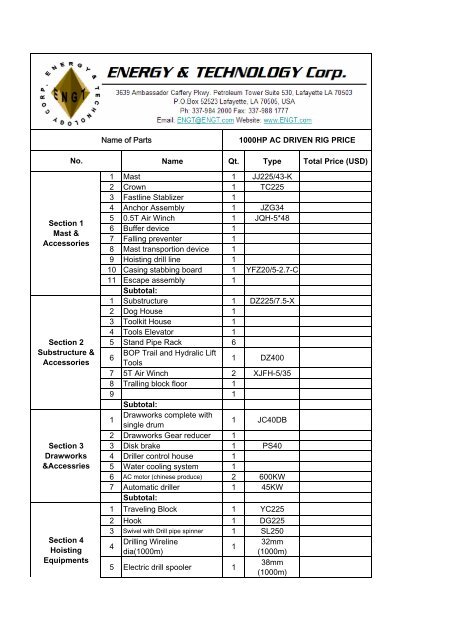
Name of Parts 1000HP AC DRIVEN RIG PRICE<br />
Name Qt. Type Total Price (USD)<br />
1 Mast 1 JJ225/43-K<br />
2 Crown 1 TC225<br />
3 Fastline Stablizer 1<br />
4 Anchor Assembly 1 JZG34<br />
5 0.5T Air Winch 1 JQH-5*48<br />
6 Buffer device 1<br />
7 Falling preventer 1<br />
8 Mast transportion device 1<br />
9 Hoisting drill line 1<br />
10 Casing stabbing board 1 YFZ20/5-2.7-C<br />
11 Escape assembly<br />
Subtotal:<br />
1<br />
1 Substructure 1 DZ225/7.5-X<br />
2 Dog House 1<br />
3 Toolkit House 1<br />
4 Tools Elevator 1<br />
5 Stand Pipe Rack 6<br />
6<br />
BOP Trail and Hydralic Lift<br />
Tools<br />
1 DZ400<br />
7 5T Air Winch 2 XJFH-5/35<br />
8 Tralling block floor 1<br />
9<br />
Subtotal:<br />
1<br />
1<br />
Drawworks complete with<br />
single drum<br />
1 JC40DB<br />
2 Drawworks Gear reducer 1<br />
3 Disk brake 1 PS40<br />
4 Driller control house 1<br />
5 Water cooling system 1<br />
6 AC motor (chinese produce) 2 600KW<br />
7 Automatic driller<br />
Subtotal:<br />
1 45KW<br />
1 Traveling Block 1 YC225<br />
2 Hook 1 DG225<br />
3 Swivel with Drill pipe spinner 1 SL250<br />
4<br />
Drilling Wireline<br />
dia(1000m)<br />
1<br />
32mm<br />
(1000m)<br />
5 Electric drill spooler 1<br />
38mm<br />
(1000m)
No.<br />
Section 5<br />
Rotary Table &<br />
Accesories<br />
Section 6 Power<br />
Generation,SCR<br />
Unit, MCC,&<br />
Power<br />
Distribution<br />
System<br />
section 7 air<br />
supply system<br />
Section 8<br />
Well Site Lighting<br />
and AC Motor<br />
Control<br />
System/Earthing<br />
System<br />
Section 9<br />
Mud Pumps &<br />
Accesories<br />
Name Qt. Type Total Price (USD)<br />
6 Elevator Link<br />
Subtotal:<br />
1 DH250<br />
1 Rotary Table 1 ZP275<br />
2 Chain reducer 1<br />
3 Carbin shaft 1<br />
4<br />
3 1/2" and 5 1/4" Roller<br />
Bushing for Hex. Kelly<br />
5 Master Bushing<br />
6 Split Bushing 2 3/8"-8 5/8"<br />
7 Split Bushing 9-5/8"-10-3/4"<br />
8<br />
Split Bushing 11-3/4"-13-<br />
3/8"<br />
9 Bushing puller<br />
10 Bit Breaker plate<br />
11 AC motor (chinese produce)<br />
Subtotal:<br />
600KW<br />
1<br />
Engine / Generator Units<br />
(detriot)<br />
3 CAT3512B<br />
2 Generator Master Skid 3<br />
3 Generator house 1 400KW<br />
4 VFD/MCC 1<br />
Subtotal:<br />
1<br />
Electric screw air<br />
compressor<br />
2 LS12-50HH<br />
2 Air dryer 1 HDS-6NF<br />
3 Air tank 2<br />
4 Air store house 1<br />
5<br />
Cold start engine drive air<br />
compressor<br />
subtotal:<br />
1<br />
1<br />
AC Supply &Lighting<br />
System<br />
1<br />
Subtotal:<br />
Mud Pumps F 1600 2 F 1300<br />
2<br />
Mounted Skid Mud Pumps<br />
Belt-driven Unit<br />
2<br />
3 AC motor (chinese produce)<br />
Subtotal:<br />
2 1200KW<br />
1
No.<br />
Section 10<br />
Stand Pipes and<br />
Rotary Hose<br />
Section 11<br />
Mud Circulating<br />
System & Solid<br />
Control<br />
Equipments<br />
Section 12<br />
Fuel, Air & Water<br />
Supply System<br />
Section 13<br />
BOP Equipments<br />
Name Qt. Type Total Price (USD)<br />
1<br />
Mud Manifold 4"*5000psi<br />
wp (double stand pipe)<br />
1<br />
2 Rotary Horse (65ft)<br />
Subtotal:<br />
2<br />
1 Desander 1<br />
2 Degasser 1<br />
3 Desilter 1<br />
4 Sand Pumps 2<br />
5 Mixing Pumps (75hp) 2<br />
6 Charge Pumps (50hp) 2<br />
7 Agitators (15hp)<br />
8 Mud Tanks 5<br />
9 Material House 1<br />
10 Mud mixing device 1<br />
12 Centrifuge 2<br />
13 Shale shaker<br />
Subtotal:<br />
2<br />
1<br />
1<br />
1 Diesel Tank 2 55M 3 +45M 3<br />
2 Water Tank 1 80M 3<br />
1<br />
2<br />
3<br />
Subtotal:<br />
13-5/8"x5000 Annular BOP<br />
FH35-35/70<br />
13-5/8"x10000 Double Ram<br />
BOP 2FZ35-70<br />
13-5/8"X10000 Single Ram<br />
BOP FZ35-70<br />
4 Dilling Spool FS35-70<br />
5<br />
Choke manifold 4 1/16"-<br />
10000psi<br />
6 Kill Manifold, 10000psi<br />
7 Ajustable Jiont TD35-70<br />
F35-<br />
35<br />
220M 3<br />
made in China
No.<br />
Section 14<br />
Drilling<br />
Instruments<br />
Section 15<br />
Drill String<br />
Section 16<br />
Hydraulic Power<br />
Tools<br />
Section 17<br />
Assembling Parts<br />
and Other Tools<br />
Section 18<br />
Rig-up,<br />
Cimmission,<br />
Packing and<br />
Training<br />
Section 20<br />
Freight of<br />
Shipping to<br />
Tianjin Port<br />
Name Qt. Type Total Price (USD)<br />
8 Variable Flange F28/35-70<br />
9<br />
Remote contral panel FKQ<br />
1280-7<br />
10 Manifold<br />
poor boy degaser 1<br />
Subtotal:<br />
Instrumentation 1<br />
1<br />
Subtotal:<br />
1 Hexagonal Kelly 5-1/4" 2 75ft、 65ft<br />
Subtotal:<br />
1 Power Tong 1 ZQ 203-100<br />
2 Hydraulic power cathead 2 100KN<br />
3 Hydraulic power station<br />
Subtotal:<br />
1 YZ120<br />
1<br />
General assembly parts<br />
(1set)<br />
1<br />
2<br />
Complete set of standard<br />
tool<br />
1<br />
3 Complete set of slings<br />
Cable for<br />
1<br />
4 Tray(grasshopper),oil,water<br />
and air<br />
1<br />
5 Video-superviser 1<br />
6 Catwalk<br />
Subtotal<br />
Rig-up,Commission,<br />
2<br />
1 Assembly, Test, Packing<br />
and Training in Factory<br />
1<br />
2<br />
Rig-up,Commission,<br />
Assembly, Test, and<br />
Training on site<br />
Subtotal:<br />
1 Inland Freight 1<br />
Subtotal:<br />
1<br />
4<br />
1
No.<br />
Section 21<br />
Documents Along<br />
With Rig<br />
Section 22<br />
Top Drive<br />
Section 23<br />
Fast Moving<br />
Device<br />
Name Qt. Type Total Price (USD)<br />
1 Documents along with Rig 3<br />
Subtotal:<br />
1 Varco TDS10A 1<br />
Fast Moving Device 1<br />
TOTAL PRICE $10,065,000.00<br />
Price Subject To Change
Technical Agreement of ZJ40/2250D Drilling Rig
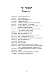
<strong>Contents</strong><br />
SECTION 1 ZJ40/2250D Drilling Rig General Description<br />
SECTION 2 Mast and Accessories<br />
SECTION 3 Substructure and Accessories<br />
SECTION 4 Drawworks and Accessories<br />
SECTION 5 Hoisting System<br />
SECTION 6 Rotary Table and Accessories<br />
SECTION 7 Power system, Power Transmission System and Air Supply System<br />
SECTION 8 Well Site Lighting, AC Motor Control System and Earthing System<br />
SECTION 9 Mud Pumps and Driving Unit<br />
SECTION 10 Mud Circulating System<br />
SECTION 11 Mud Solid Control System<br />
SECTION 12 Fuel & Water Supply System<br />
SECTION 13 BOP and Control Euipments<br />
SECTION 14 Drilling Parameter Instruments<br />
SECTION 15 Drilling String<br />
SECTION 16 Well Head Equipments and Tools<br />
SECTION 17 Top Drive<br />
SECTION 18 Assembly and Commission<br />
SECTION 19 Spars Parts List<br />
SECTION 20 Painting And Packing<br />
SECTION 21 Transport<br />
SECTION 22 Documents Along With Rig<br />
ATTACHMENT1 Tools for Drilling Rig<br />
ATTACHMENT2 Crane Rope List
SECTION 1 ZJ40/2250D Drilling Rig General Description<br />
1. General Description<br />
1.1 Uses and Features<br />
ZJ40D drilling rig is a kind of DC electrical drilling rig designed and manufactured for exploring<br />
and developing oil and gas resources. The drilling rig is designed according to rules specified in<br />
GB5609-1999 “Model of Petroleum Drilling Rig and basic parameters” and complies with<br />
requirements in API specification of USA and other international advanced standards. Deep<br />
drilling capacity of drilling rig is 4000m.<br />
Electrically driven mode of drilling rig is AC-SCR-DC. AC power output by generator groups is<br />
controlled by electrical control system and fed to DC motor to drive respectively draw-works,<br />
rotary table and two sets mud pumps.<br />
Draw-works is driven by two sets 800KW DC motor. Lifting gearshift is 4 steps less speed<br />
specification. The rotary table is driven by one set 800KW DC motor. Transmission of rotary table<br />
is through 2 steps less speed specification. Reverse gear is achieved by reversal of motor. Main<br />
brake of draw-works utilizes disc brake and auxiliary brake of draw-works uses EATON brake.<br />
Main bodies of mast and base for drilling rig are integral lifting structures. Firstly, lift the mast by<br />
draw-works and fix the mast. Then lift the base also by the drawworks until the base reach the<br />
working position.<br />
Two sets F-1300 mud pumps are equipped on the drilling rig that is driven respectively by two<br />
sets 800KW DC motors through narrow and joined V-belt. Under the control of control system,<br />
Two sets of electric screw air compressors, air tanks and dryer are equipped for air supply of<br />
drilling rig.<br />
Safe and complete power supply and lighting system for well field is equipped on the drilling rig.<br />
Quick connectors that are safe and reliable and convenient for installation and dismantling are<br />
used at the connections of all cables<br />
Solid control system of drilling rig is composed of three mud tanks and equipped with complete<br />
mud purification equipment mainly including shale shaker, vacuum degasser and mud cleaner<br />
(de-sanding and de-silting) etc<br />
1.2 Basic Parameters of Technical<br />
Nominal Drilling Depth<br />
(114mm,4 1 /2″) 2500m~4000m<br />
(127mm,5″) 2000m~3200m<br />
Max. Hook Load 2250KN<br />
Lines Of Hoisting System 5×6(Clockwise)<br />
Dia. Of Drilling Line 1 1/4″(φ32mm)<br />
Drawworks Rated Power 735kW (1000HP)<br />
Drawworks gears 4gears, stepless<br />
Main brake Hydraulic Disk Brake(wind cooling)<br />
Auxiliary Brake 236WCB2 EATON brake(Water cooling)<br />
Rotary Table Opening Size φ698.5mm(27 1 /2")<br />
Rotary gears 2 gears, stpless<br />
Mud Pump Rated Power 956KW (1000HP)<br />
Height of Mast 43m<br />
Mast Type K
Capacity of Standpipe 4000m<br />
(4 1/2″drill pipe,28m standpipe)<br />
Height of drill floor 7.5m<br />
Main Generator No. 3<br />
Main Parameters 1085KW,60Hz,1200r/min,600V<br />
Electrical Transmission Mode AC-SRC-DC<br />
Drawworks motor power×No. 800kW×2<br />
Single pump motor power×No. 800kW×2<br />
Rotary table motor power×No. 800kW×1<br />
Drilling Fluid Manifold<br />
(Double Stand Pipe) Ф103mm (4”) ×35MPa<br />
Mud tank 3<br />
Effective Capacity 200m 3<br />
Air Storage Tank 2+2×2.5m 3<br />
Air Source Pressure 1MPa<br />
Diesel Tank 2(45 m 3 +55m 3 )<br />
Industry Water Tank 80m 3<br />
Forced Cooling Water tank 20m 3<br />
1.3 General layout of drilling rig<br />
Layout of drilling rig is divided into substructure zone, power zone, pump room, solid control<br />
zone and supply oil & water zone etc. Pipeline and cable trough are laid on the ground. Pipeline<br />
and cable trough of top substructure are folded in order that cables and pipelines need not be<br />
removed during moving and transportation as the whole can be realized<br />
In drilling floor zone, there are various implement required in drilling operation including mast,<br />
base, drawworks, rotary table, traveling block, hook block, swivel, driller’s house, doghouse, tools<br />
house, hydraulic cathead and 5 ton air winches etc<br />
In power zone, there are generation house, gas source device and electrical control house.<br />
In pump room, there are two sets F-1300 pump units and high-pressure mud manifold etc.<br />
In solid control zone, solid control system includes mud tank and mud processing equipment etc.<br />
In supply oil & water zone, there are industry water tank, diesel tank, diesel backing tank and<br />
engine oil tank etc.<br />
Cable trays are used in cable connection among all zones of drilling rig. Oil, gas and water<br />
pipelines and all kinds of cables are laid in cable tray. Ramp and racking of drilling rods are<br />
installed in front of the substructure.<br />
1.4.Range of use for drilling rig<br />
The range is mountain area that is within 1000m higher than the sea level.<br />
Ambient temperature(summer): 45℃,humidity:35%<br />
Ambient temperature(winner):-20℃,humidity:60%
Section 2 Mast and Accessories<br />
2.1 1set JJ225/43-K2Mast<br />
2.1.1 General description<br />
JJ225/43-K2 mast is connected by the pins, which takes the H-type steel as the main supporting<br />
leg and front open without guy line. It is assembled at low position and raised up by the<br />
drawworks. The mast assembles with the crown block, drawworks and other part to the complete<br />
drilling rig. As the key part of the rig, the mast perform the following services like assembling<br />
crown block, hanging traveling system, hanging drilling tools for drilling pipe and casing job. The<br />
design conform the API Spec 4F and satisfied with assembling top drive.<br />
2.1.2 Technical parameter<br />
Nominal drill depth<br />
114mm(4 1/2″DP) 4000m<br />
Max. Hook load 2250 kN<br />
Working height (From drilling floor the crown block beam bottom surface) 43.2 m<br />
Top span (front ×side) 2 m×2 m<br />
Bottom span (front ×side) 8 m×2.7m<br />
Height of the monkey board 24.5m; 25.5m;26.5m<br />
Capacity of standpipe 4000m<br />
Wind load capacity<br />
Full setback no hook load 36m/s<br />
No setback no hook load 47.8m/s<br />
Rig-up & rig down ≤8.3m/s<br />
2.1.3 Main structure and working principle<br />
2.1.3.1The mast make up of main body、A-frame、monkey board、ladders、standpipe console、<br />
raising devise and other accessories.<br />
2.1.3.2 Mast is connected by the pins, which takes the H-type steel as the main supporting leg and<br />
front open without guy line. It is assembled at low position and raised up by the drawworks<br />
2.1.3.3 The main body of the mast is divided into four sections connecting with pins and auricular<br />
board. Transport storage can be stacked equipment, transport vehicles and reduced inventory area.<br />
2.1.3.4 The mast shall be mounted at low-altitude and level, and raised & lowered integrally via<br />
the A frame on drilling floor. The mast is connected with the A frame using pins.<br />
2.1.3.5.A- guide pulley is set on the main cross beam of A frame for winding of the fast line<br />
during lifting of the mast for support and guide of fast line.<br />
2.1.3.6The ladders are placed on left/right of mast, the worker can go to the casing stabbing、<br />
monkey board and crown block through drill floor by left one; and can go to the standpipe console<br />
by right one.<br />
2.1.3.7 After the mast is lifted in place, the amortizing hydraulic cylinder which is fixed on A<br />
-frame will work and perform original top-shoving for lowering of the mast.<br />
2.1.3.8 Wind deflectors shall be mounted for the mast body near the monkey board and around the<br />
monkey board, so as to reduce wind attack during operation of the mast.<br />
2.2 Crown block<br />
2.2.1 Technical Parameter<br />
Max hook load 2250KN
Number of pulleys 6<br />
Pulley OD Φ1120mm<br />
Pulley BD Φ1010mm<br />
Sand pulley OD and Q’ty Φ610mm 1<br />
Dia. of wire rope Φ32mm<br />
2.2.2 Constitution and feature<br />
2.2.2.1 Crown block mainly consists of frame, pulley block assembly, fast line pulley assembly,<br />
auxiliary pulley, handrails, anti-collision equipment, sand pulley, hoist frame and guard etc.<br />
2.2.2.2 The crown block frame is designed complying with specification API Spec 4F. It is a<br />
complete weld structure, the main two carlings and two beams are welded using 16Mn plate, and<br />
the main weld is detected by magnetic powder. The upper part of crown block frame is connected<br />
with the pulley block axle base and fast line guide pulley axle base via bolts. The crown block<br />
frame is connected with the mast via 2 Φ30 position pins, and fixed onto the mast via 12 M30<br />
bolts.<br />
2.2.2.3 The pulley block assembly consists of main shafts, supports, 5 pulleys and bearings etc.<br />
One conical dual-row roller bearing is mounted between each pulley and shaft to ensure easy<br />
rotation of the pulley, steady and anti-axial force. One grease nozzle for applying grease for the<br />
pulley is mounted at the end of shaft, and each bearing is equipped with an independent lubricant<br />
path, convenient for filling grease into the bearing to keep smooth pulley rotation. The pulley rope<br />
groove is designed according to API Spec 8A specification.<br />
2.2.2.4 The fast line pulley assembly consists of shafts, supports, pulleys and bearings etc. One<br />
grease nozzle is mounted at the end, convenient for applying grease for the bearing<br />
2.2.2.5 The crown block is equipped with 4 groups of auxiliary pulleys, and one grease nozzle is<br />
mounted at the end of each pulley. The auxiliary pulley is used for lifting by pneumatic drawworks<br />
with max load 5T.<br />
2.2.2.6 Sawn lumbers are set under the crown block frame for anti-collision of crown block, which<br />
amortizes knocking into the crown block by traveling block<br />
2.2.2.7 The cantilever-type hoist frame is used for maintenance of crown block. The capacity of<br />
truss type pulley hoist frame is 2T, sufficient for lifting of heaviest parts on the crown block.<br />
2.2.2.8 One top driving guide eyebolt is mounted on the crown block frame for top driving of<br />
Varco.<br />
2.3 1 set Crown Block Collision Preventer<br />
The anti-collision system of ZJ40/2250D drilling rig adopts three (3) safety systems:<br />
1. The collision preventer that is mounted on the upper section of the mast to limit the elevating<br />
position of the traveling block;<br />
2. Drawworks anti-collision overwind valve device.<br />
3. Traveling block digital screen anti-collision device (included in the electric control system)<br />
2.4 1set JQH-5×48 Air Winch<br />
Rated Air pressure 0.8 MPa<br />
Rated air consumption ≤1.34m 3 /min<br />
Rated Force 5kN<br />
Rated Speed 48m/min<br />
Dia. of Wire Line 8mm (0.3”)<br />
Rated power 2.6kw
Capacity of wire line 60m<br />
Weight 116kg<br />
With Φ8 mm wire rope 60 meters, with a fierce repression, with shirking clasp, wire rope painting<br />
protective oil exports<br />
2.5 Hydraulic Casing Stabbing<br />
Parameters of technical<br />
Vertical range of operation: 5.0m<br />
Maximum angle of lifting of the major arm: 0-90°<br />
Maximum reach of the major arm: 0-0.6m<br />
Capacity of the mechanical hands: 5"-20"<br />
Maximum angle of swing of the mechanical hands: ±12°<br />
Upgrade weight: 200kg<br />
Rated displacement: 15 L/min<br />
Rated pressure: 16MPa<br />
2.5.2 Platform technical Parameters<br />
a) Upper platform 400mm<br />
b) Load of the platform 200kg<br />
2.5.3 Hydraulic fountain parameters<br />
a) Rated working pressure 10MPa<br />
b) Max. Working pressure 16MPa<br />
c) Max. Flow 15 L/min<br />
d) Motor power 3kw<br />
2.5.4Function<br />
The Full-hydraulic Casing Centralizing machine can accomplish Casing’s Centralizing (to link<br />
with the Casing)while the dill-well’s working of the setting down Casing so it replaces worker to<br />
set down Casing by hand and comes true mechanization’s working of the setting down Casing.<br />
Use working of centralizing Platform<br />
When it will be by manual work the platform is sling and fixed to the spare aures-plank on sliding<br />
carriage, to put on the peg and insert the pin. Then the machine is rise to need position and insert<br />
the anti-fall peg, in this way the worker may come to there and operating.<br />
2.6. 1 set RG10D Escape Device<br />
The RG 10 D escape device with which one person, or several persons sequentially, can descend<br />
from a high place to a low place at a limited speed<br />
2.6.1 Executive standard: production followed by European Standard EN341<br />
2.6.2 Technical Parameters<br />
Max load capacity: 130kg<br />
Diameter of wireline: ф10mm<br />
Length of the wireline: 45m<br />
2.7 1set Deadline anchor<br />
Executive standard: SY/T5320-2000<br />
Anchor: JZG34A,1-1/4"(Φ32mm)<br />
weight indicator type: JZ400B<br />
Available wire line: 10
The deadline anchor is fixed on the right Ⅰsection mast which it is 2.445m to the drilling floor<br />
opposite to the driller’house.<br />
2.8 1 set Traveling block floor<br />
Support the traveling block and hook before rig-up and store spare parts.
SECTION 3 Substructure and Accessories<br />
3.1 Substructure<br />
3.1.1 Usage and scope<br />
This DZ225/7.5-s base is one of the important components of ZJ40D drilling rig, designed to<br />
arrange, support and fix the mast, rotary table etc, as well as their own weight, drill tools load and<br />
casting load. In addition, it is used to store DP and necessary drilling tools, and provide necessary<br />
platform for roughneck.<br />
Nominal drilling depth (4-1/2″DP) 4000m<br />
Rotary table Max. Load 2250kN<br />
3.1.2 Technical parameters<br />
Height of substructure surface 7.5m<br />
Area of substructure 12.4m×10.3m<br />
Clearance height (from beam Bottom surface of rotary table to the ground) 6.26m<br />
Rotary table beam load 2250KN<br />
Mast lower span 8m<br />
Stand box volume 5″28 m stand 4000m<br />
3.1.3 Main constitution<br />
3.1.3.1 This base is of lift parallelogram structure, mainly consisting of bottom layer, middle layer,<br />
top layer as well as rotate oblique ladder, ramp, tools ramp, slide escape and handrails etc.<br />
3.1.3.2 Bottom layer consisting of left/right front lower base and left/right rear lower base, and<br />
Ø100 pins are used to connect front/rear lower bases. The bottom layers are connected via two<br />
bottom beams and one slanting beam.<br />
3.1.3.3 Middle layer mainly consist of two front poles, two rear poles and four diagonal bars.<br />
3.1.3.4 Top layer mainly consisting of left/right upper base, pipe setback beam, rotary table beam,<br />
support beam and BOP lifting device.<br />
3.1.4 Principle<br />
3.1.4.1 Mount the bottom layer and top layer of base, connect the front pole, diagonal bars and<br />
rear pole, and mount the substructure at low-altitude. The left/right beams of top layer will be<br />
mounted after the mast and base are lifted in place.<br />
3.1.4.2 Remove the 8 pins between the bottom layer and top layer after the mast is lifted in place.<br />
The base is lifted to work position after changing the parallelogram which consists of bottom layer,<br />
top layer, front pole, diagonal bars and rear pole by power from drilling rig drawworks and via the<br />
traveling system in upright mast as well as the rope for lifting of the mast<br />
3.1.4.3 Hydraulic buffer device helps to raise the substructure reaching the working position<br />
smoothly.<br />
3.1.4.4 Before lifting the base in place, open the amortizing hydraulic cylinder (fixed on the A<br />
frame) for raising & lowering of the base, to extend the cylinder lever against the base. Retract the<br />
cylinder lever as lifting the base to position the base steady and safe. For lowering of the base,<br />
after the top layer of base is pushed over the dead point by the raising & lowering cylinder, the<br />
base is lowered slowly by gravity. Insert pins after the base is in place.<br />
3.2 2 sets Dog House and Toolkit house<br />
3.2.1、Overall dimensions 7m×2.5m×2.8m<br />
7.4m×2.6m×2.8m。<br />
3.2.2 Substructure of house
3.2.2.1 Bottom girder adopts 25# I beam,bridging beam adopts 12# channel beam, hanging bar<br />
and towing bar adopt φ114 steel tube;roof board adopts 560--type profiling corrugated board with<br />
the depth of 3mm, and the roof is designed with cable caging device.<br />
3.2.2.2The drilling worker side-room is divided into two parts: the left part is installed hydraulic<br />
power source, the right part is retiring room for workers and staff members with 1 long chair, 1<br />
stainless steel, 1 set of fixed chair and table, steel document cabinet and 2 .2kg Fire Extinguisher.<br />
3.2.2.3 The tool-house is divided into two parts: one part is the position for implement hydraulic<br />
power source, with the width of 1500mm; the other part is the position for tool box, table vice and<br />
storage racks etc.<br />
3.2.2.4 Indoor decoration: the inner wall adopts δ16 high density anti-firing plate with grey<br />
white batten. The floor is divided into two layers which the upper layer is made by δ6 checkered<br />
steel plate and the lower layer adopts δ5 to pack the bottom beam. The inner wall of the toolkit<br />
house adopts δ3 1260mm height steel plate as the protection wallboard avoiding inner wall<br />
breakage.<br />
3.2.2.5 Door, window& thermal isolation: the door is anti-fire security door and the window is<br />
plastic steel window. The thermal isolation material adopts 100mm rock wool.<br />
3.2.2.6 Every room installs smoke alarm, emergency lamp, explosion proof air exchange fan and<br />
power leakage protection device. The dog house has a 1.5p explosion proof air conditioner.<br />
3.3 1 set BOP Trail and Lift Tools<br />
3.3.1 Main constitution and basic parameters<br />
Handling System is designed to meet the requirement of installing and removing BOP stacks.<br />
Technical Specifications:<br />
Max. Lift Capacity 2×200=400KN<br />
Max. Lift Height 3.2m<br />
Max. Lift Speed 26.3mm/s<br />
Max. Lowering Speed 55.8mm/s<br />
Max. Horizontal Moving Speed 12m/min<br />
Max. W.P. Hydraulic System 16Mpa<br />
Max. Flow Hydraulic System 120L/min<br />
Dia. of Wire Line Φ28mm<br />
3.3.2 Structure and Features<br />
DZ-400、BOP Handling System is designed to meet the requirement of installing and removing<br />
BOP stacks. The system adopts full-hydraulic control and can be used for large and medium<br />
drilling equipment. The main function of system is to lift and can be used for large BOP or BOP<br />
stacks .The system features with explosion-proof, easy operating, good reliability, and safety.<br />
Controlled by hydraulic operating box, the two lift devices hung on two guide rails each below the<br />
drilling floor can achieve the movement of rise, lowering, move forward and backward<br />
synchronous, or move forward and backward asynchronously, rise and lowering with limited<br />
separation distance (less than lm).It is convenient for installing and removing BOP stacks.<br />
3.3.3 Others<br />
BOP Handling System is powered by hydraulic station for floor mechanical tools of drilling rig<br />
3.4 2set XJFH5/35windlass<br />
Rated Force 50kN<br />
Max. Speed 35m/min (115ft/min)
Rated Power 16kW (22hp)<br />
Air pressure 0.8Mpa<br />
Rated air consumption 12.7m 3 /min<br />
Max. Length of Line 120m<br />
3.5 2set Mouse and rat hole<br />
Mouse Specifications 13 3/8″<br />
Rat Specifications 10 3/4″<br />
3.6 2set catwalk<br />
The hight 1070mm,two parts.<br />
3.7 8 piece Drill pipe rack<br />
The hight 1070mm<br />
3.8 1 set Cable tray<br />
Include folding overhead cable tray and ground-based cable tray.
SECTION 4 Drawworks and Accessories<br />
4.1 1 set Drawworks<br />
4.1.1 Parameters of technical<br />
Rated Input Power 735KW(1000 HP)<br />
Dia. of Wire Line φ32 mm<br />
Max. Fast Line Pull 280 kN<br />
Drawworks gears 4gears<br />
Drum(Groove)Size(H×L) φ660×1173 mm<br />
Disc brake size φ1520×40 mm<br />
Max Brake Torque of Eaton brake 66611Nm<br />
API SPEC 7K designed to requirements and SY/T5532-2002<br />
norms<br />
4.1.2 Driving principle<br />
This drawworks mainly consists of DC motor, input shaft, intermediate shaft, roller shaft and<br />
Eaton brake etc.<br />
Power is input by DC motor to input shaft. Two stages are provided via two chains between the<br />
input shaft and intermediate shaft (two engaging/disengaging mechanisms consisting of two chain<br />
wheels without sleeve on intermediate shaft and airbag push type plate clutch at both ends), and<br />
two stages are provided via two chains between intermediate shaft and roller shaft (two chain<br />
wheels without sleeve on roller shaft connected rigidly with the brake rub, and form two<br />
engaging/disengaging mechanisms together with high/low speed air tube clutch), forming 2×2<br />
level grades in total together with various clutches.<br />
4.1.3 Constitution and feature<br />
Drawworks is designed as panel type three-shaft one. The driving chain is cooled and lubricated<br />
with forced lubricant, and circuiting water-cools the Eaton brake. The chain wheel without sleeve<br />
on intermediate shaft is connected with airbag push type plate clutch, controlling<br />
charging/discharging of airbag push type plate clutch cylinder via pneumatic valve, so as to<br />
transfer power via the intermediate shaft and providing various speeds; High/low speed air tube<br />
clutches are set at both ends of the roller shaft, controlling charging/discharging of air tube and<br />
providing various roller speeds. 236WCB2 Eaton pneumatic disc brake is employed for the<br />
auxiliary brake of drawworks, which is connected with the roller shaft via teeth clutch<br />
4.1.4 Anti-collision crown block<br />
Purpose of the anti-collision equipment: As the traveling/lifting system lifts to the limit, the limit<br />
device gives signal and the anti-collision valve works to discharge the air tube clutch on the roller<br />
shaft (high-speed or low-speed), shut off the power source for the roller shaft; At the same time,<br />
the hydraulic disc brake operates in emergency, the roller stops, so the traveling/lifting system<br />
stops lifting, avoiding collision to the crown block, ensuring safety of drilling rig. Two sets of<br />
anti-collision equipments are mounted for this drilling rig, one set is on upper part of the mast, a<br />
wire rope anti-collision equipment to limit lifting of traveling block, the other set is drawworks<br />
anti-collision ring valve<br />
4.2 EATON 236WCB2
236WCB2 brake has four dynamic friction discs with water cooling and pneumatic compression.<br />
After air pressure is applied on this brake cylinder, it compresses four dynamic friction discs with<br />
water-cooling to produce braking force. Adjusting air pressure of brake can change brake moment<br />
that is proportional to the air pressure.<br />
Brake Torque (under 0.55MPa): 66661 kN.m<br />
Max. Pressure: 1.03 MPa<br />
Initial Pressure: 0.041 MPa<br />
Max. Idling Speed of Brake Disk: 700 RPM<br />
Max .Running-in Speed of Brake Disk: 475 RPM<br />
Max. Pressure of Cooling Water: 0.41 MPa<br />
Flow rate of cooling water: 492L/min<br />
4.3 1set Hydraulic disk brake<br />
4.3.1 Technical requirement<br />
4.3.1.1 The design and manufacture of the break disc conform to SY/T5609 ZJ40D Parameters of<br />
technical of drilling rig and requirement of drilling technique. Ambient temperature -25ºC~+55ºC,<br />
humidity:90%(+20 ºC)<br />
4.3.1.2 Hydraulic disk brake system can meet 4000m drawworks’functions of service brake,<br />
emergency brake, parking brake and overwind protective brake.<br />
4.3.1.3Hydraulic disk brake adopts compounding structure of four normally open working calipers<br />
and two normally closed safe calipers.<br />
4.3.1.4 Hydraulic disk brake is complete with two air cooling brake disks fitted on the two sides of<br />
drawworks drum.<br />
4.3.1.5 Brake disc of the working calipers and safe calipers which are high temperature proof and<br />
fray proof are interchangeable and adopt material without asbestos.<br />
4.3.1.6 Hydraulic station has functions of dual oil source, dual circuit and multi protection to<br />
ensure work’s liability.<br />
4.3.1.7 Control system is hydraulic contol opration and the operation handle is mechanical brake<br />
handle<br />
4.3.2 Parameters of technical<br />
Nominal drilling depth 4000 m<br />
Rated working pressure 6.5 Mpa<br />
No. of open working calipers 4<br />
No. of closed safety calipers 2<br />
Dia. of brake disk 1570 mm<br />
Cooling method air cooling<br />
Workings caliper Max. Normal positive pressure 65 kN<br />
Safeties caliper Max. Normal positive pressure 75 kN<br />
Hydraulic station:<br />
Single pump rated flow rate 15L/min<br />
Oil tank volume 90 L<br />
Motor power 2x2.2 kW<br />
Capacity of the accumulator 4x6.3 L
Electric heater power 1 kW<br />
Cool water flux 2 m 3 /h<br />
4.3.3 Functions description<br />
Service Brake: Through operating the handle of the brake valve, adjust the service caliper’s<br />
normal pressure on the friction disc. So provide adjustable braking torque to the rigs to meet<br />
requirements in different working conditions, such as bit feeding, tripping etc<br />
Emergency Brake: Under emergency condition, press the Red emergency brake button, the<br />
service calipers and safety calipers will all applied to realize emergency stop。<br />
Parking Brake: When the drilling rig will stop working or the driller wants to leave the driller’s<br />
station, pulling down the parking brake handle will realize safety calipers braking to prevent the<br />
hook from sliding.<br />
Over-winding Protection When the hook is lifted to a certain height with load the service brake<br />
should be actuated but not did, due to the driller’s failure in operation and some other reasons, the<br />
over winding or colliding prevention system will stop air supply of the disc brake control unit to<br />
realize emergency stop for preventing crown block accident.<br />
4.4 1 set Fast line guide Manual<br />
Technical parameter<br />
Wire ropes diameter: 32mm<br />
Max rope speed: 50m/min<br />
Weight: 300kg<br />
Fix it on the top of drawworks<br />
4.5 2 set DC motor<br />
4.5.1 Ambient condition<br />
The Ambient condition temperature:-30℃~+45℃<br />
Height: height above sea level≤1200 m<br />
Humidity: +20℃Relative humidity≤90%<br />
4.5.2 DC motor Basic Data<br />
Rated Power 800kW<br />
Rated Voltage 750V<br />
Rated Current 1150A<br />
Rated Speed 970r/min<br />
Rated Efficiency 92.7%<br />
Max. Current 1600A<br />
Max Speed 1500r/min<br />
Excitation Series<br />
Duty continuous<br />
Insulation (Stator/Rotor) H/H<br />
Cooling method air forced<br />
Air blower 11kW、460V、60Hz<br />
Other requirements<br />
Each drawworks is complete with standard single shaft extension coupling, including 12 coupling<br />
bolts.<br />
Positive pressure air explosive-proof line connection box with protective grade of IP54 and 20<br />
core control cable and electric outlet/plug.
with space heater(220V、200W);<br />
With auxiliary switch (plus locking device)<br />
With wind compress switch<br />
4.6 1 Set Explosion proof industry monitor<br />
4.6.1 Main Specifications:<br />
Rated voltage: 220v<br />
Rated frequency: 50HZ<br />
Operating condition: -30°C to +60°C<br />
4.6.2 Parameters of technical<br />
4.6.2.1System component<br />
Totally sealed in the explosive proof and dust proof protective cover, explosive proof grade is IP65.<br />
Explosive proof clouds terrace vertical turning angle is ±45° while horizon turning angle reach<br />
0°-345°.<br />
4.6.2.2LCD<br />
To display video image and date<br />
The product adopts high brightness LCD (with AV input) and explosive proof shell.<br />
4.6.2.3Controller<br />
Vidicon, lens and clouds terrace is operated by control keyboard.<br />
The center of the system mainly consist of central circuit board, screen division unit, central power,<br />
monitor power, camera power and pan/tilt unit power etc<br />
4.6.2.4All the cameras and platforms can be controlled by control panel, and such functions as<br />
pan/tilt and zoom/focus can also be adjusted through control panel<br />
NAME monkey pump<br />
vibrating<br />
drum<br />
total<br />
board house<br />
screen<br />
front-end<br />
terminal<br />
WANDEOR 1set 1set 1set 1set 4set<br />
Ex-protective cover 1set 1set 1set 1set 4set<br />
tripod head 1set 1set 2set<br />
Ex-tripod head 1set 1set 2set<br />
Finished parts for buildings 1set<br />
Ex-LCD monitors 1set<br />
control 1set<br />
composite cable 50m 60m 30m 50m 190m<br />
4.7 1set Driller’s control cabin<br />
4.7.1 GENERAL DESCRIPTION<br />
The design, manufacture and assembly of drilling machine managing and controlling room<br />
complies with relevant national and international criteria (ISO9001) and relevant criteria of<br />
petroleum corporations; capability of drilling machine managing and controlling room meets<br />
relevant HSE demands and regulations. It is highly explosion proof, sand proof, shockproof, damp<br />
proof, sound insulation, heat insulation and antisepsis. Electric devices are located in I class 1 area<br />
and meet the requirements of explosion proof standard.<br />
4.7.2 Overall dimension and structure of Driller’s control cabin<br />
The house is consisted with pentagonal walls. The base is 200mm in height and the framework is<br />
made up of 200 groove steel. The inner side of the base is equipped with interconnected cable tray.
When all the equipments are fixed, the upper plane of the base forms a sealed integrity. Stainless<br />
steel plates are spread on the floor and special slide proof mats are spread on plain plate.<br />
The base is equipped with caging device and integral shock absorption device to ensure driller<br />
house not to move when the rig is working so that equipments will not be damaged because of<br />
shaking.<br />
The front three walls are made of §=20mm steel bulletproof glass. The front window is equipped<br />
a gas-driven scraper; when designing driller house, driller’s vision is considered in respects of<br />
instruments display, etc. The exterior surface is made of 2.5mm stainless steel plate and the<br />
interior surface is made of 2mm stainless steel plate, and the middle is temperature preserving<br />
layer.<br />
The house is equipped with a 1.5P split type explosion-proofing air conditioner. 22mm steel<br />
bulletproof glass is fixed on the top of the driller house. There are three windows on the top and<br />
above the windows, skylight is fixed. The right above glass is equipped with a gas-driven scraper.<br />
4.7.3Collocate in the house<br />
Disk brake operation valve group (emergency brake, service brake, parking brake)<br />
Cathead control valve group (electric control)\various pressure meters;<br />
Various air control operation valve, industry monitoring operation keyboard, TV monitoring<br />
display screen.<br />
Display screen of parameter meters, weight meter, adjustment button, utterance system<br />
(microphone, althorn);<br />
Electric control system operation components and display (touch screen), with top drive control<br />
cupboard.<br />
With armrest and backrest, Driller’s swivel chair, the working height of which is adjustable can be<br />
automatically lifted and lowered and satisfy the escape demand of driller;<br />
Other: air horn, 1.5P explosive proof air conditioner, 2×40Wemergency explosive proof<br />
fluorometry, portable emergency light, 2 standard extinguishers of 2kg
Section 5 Hoisting System<br />
5.1 1set (YC225)Traveling Block<br />
5.1.1 TECHNICAL SPECIFICATIONS<br />
Maximum load (12 line): 2250kN<br />
Number of sheaves: 5<br />
Diameter of sheave 1120mm<br />
Diameter of sheave groove: 32mm<br />
5.1.2 Structure<br />
YC traveling blocks is designed and manufactured according to API Spec. 8A. They are composed<br />
of the cap, sheaves, shaft of sheaves, left plate assembly, right plate assembly, lower lifting bail,<br />
pin shaftand pin housing<br />
The sheaves are supported on the shaft with double-row conical-roller bearings. Each bearing has<br />
its own lubrication channel and can individually lubricate with grease fittings located at the ends<br />
of the shaft. Dust seals at the ends of bearing are riveted on the sheaves hub. There are two sizes<br />
grooves for making customers’ option. The sheave grooves are machined as per API 8A Spec and<br />
heat treated to minimize wearing<br />
5.2 1 Set DG225 Hook<br />
5.2.1 Technical parameter<br />
Max. Hook load 2250 kN<br />
Dia. of major hook 160 mm<br />
Dia. of minor hook 100mm<br />
Spring travel 180mm<br />
Major hook opening 190mm<br />
Body’s radius of rotation 420mm<br />
5.2.2 Structure<br />
The body, bail, and bail support are welded by special alloy steel and the lower barrel and shank<br />
are forged by alloy steel. So they have higher load capacities.<br />
Pins connect the bail and bail support. The lower barrel and body are connected by left-hand<br />
threads and locked with lock key. The body and barrel move up and down along the shank.<br />
Between the barrel and spring support is provided with bronze bushings to reduce wear of the<br />
shank.<br />
Inside the barrel are mounted the inner & outer springs. When coming out of the hole, the stand<br />
will loosen and spring up. The bearings are thrust roller bearings.<br />
5.3 1 Set SL225 Dual-purpose Swivels<br />
5.3.1 TECHNICAL SPECIFICATIONS<br />
Max. Static load 2250KN<br />
Max. Speed 300rpm<br />
Max. Working pressure 35MPa<br />
I.D of the central tube 75mm<br />
Coupling:<br />
Threads to the central tube (REG)<br />
To the Kelly (REG)<br />
Gooseneck thread API Std 5B 4"-8<br />
Model of air motor FMS-20
Rated speed 2800 rpm<br />
Power 14.7Kw<br />
Rated pressure 0.6MPa<br />
Air consumption 17m 3 /min<br />
Inlet line 1 1 /2"<br />
Rated spinning speed 92rpm<br />
Max. Spinning moment 3000N•m<br />
5.3.2 STRUCTURE & PRINCIPLE OF OPERATION<br />
SL amphibious swivel consist of the rotary part, stationary part, supporting part, sealing part, and<br />
screwing part. The rotary part covers the stem and coupling. The stationary part includes the cover,<br />
lower/upper cover, and bottomor oil retainer, gooseneck, bail and bail pin. The supporting part is<br />
composed of the main bearing, upper centralizing bearing, and lower centralizing bearing. The<br />
sealing part covers the packing assembly, and upper & lower oil seals. And the screwing part<br />
contains the air motor, gear, and one-way air-controlled clutch.<br />
The stem carries the total weight of drilling string and pressure of drilling fluid. The coupling<br />
threads to the stem and to the Kelly conform to thread sizes specified in API Spec 7.<br />
Drive & Air control principle of the screwing part<br />
The two pairs of gears (for two-step reduction) are driven with the air motor and torque is<br />
transmitted to the stem so as to reach the purpose of spinning.<br />
The clockwise or counterclockwise of spinning is made by air control. The compressed air passes<br />
through the air filter, oil fogger, two-way tee air control valve and comes into the position selector.<br />
Operating air switch (in driller’s house or air control console) will change the direction of the<br />
position selector valve and the rotation of air motor to serve the purpose of spinning.<br />
5.4 1 set Electric drill spooler<br />
Output speed 8-17rpm<br />
Input Speed 720rpm<br />
Max. Torque 10000N.m<br />
Motor power 15kW<br />
The average small rope line speed 13.4m/min<br />
Capacity of rope 1200m<br />
5.5 wire rope<br />
Standards: API-9A<br />
6×19S-IWRC refacing 1-1/4"(Φ32mm),1000m<br />
Level: EIPS class<br />
The twist: Left interactive twist<br />
5.6 1 pair DH250 Elevator Link<br />
Basic parameters<br />
Rated load: 2250KN<br />
Nominal size: 2700 mm<br />
The rings on the ear with the hook connecting the ears, ear rings and elevator connecting the ear,<br />
design, and manufacturing in line with API Spec 8A norms. Nameplate API to play marker.
SECTION 6 Rotary Table and Accessories<br />
6.1 1 set ZP275 Rotary table<br />
6.1.1 TECHNICAL SPECIFICATIONS<br />
Opening size 698.5mm<br />
Max. Static load 4500kN<br />
Max working torque 27459N.M<br />
Max speed 250rpm<br />
Gear ratio 3.67<br />
6.1.2 Structure<br />
ZP375 rotary table is manly composed of turntable, cast&weld housing, input shaft assembly,<br />
lock device, master bushing and cover. The housing is made of steel casting&welded structures<br />
and it can be used as the oil tank for the bevel gears and bearings.<br />
6.2 1 set ZP-375 Rotary table Accessories<br />
20″(for 20″ casing)<br />
11 3/4″-13 3/8″(for 13 3/8″ casing)<br />
9 5/8″-10 3/4″ (for 9 5/8″ casing)<br />
2 3/8″-8 5/8″ (for 7″ casing)<br />
2 3/8″-8 5/8″ (for normal drilling process)<br />
Master bushing<br />
Elevator Links for master Bushing<br />
Elevator Links for Bushing<br />
5 1/4″ Roller Bushing for hex. Kelly<br />
3 1/2″ Roller Bushing<br />
6.3 1 set Rotary Table Transmission Box<br />
6.3.1 Technical parameter<br />
Rated Input Power 800kw<br />
Speed 2 Speeds<br />
Lubrication Thin oil forced lubrication<br />
6.3.2 Structure<br />
The rotary table drive box is connected with rotary table beam by bolts. The output shaft of motor<br />
is connected to the input shaft of the rotary table drive box via barrel-type tooth coupling, and the<br />
output shaft of the rotary table drive box is connected to ring flange or rotary table input shaft via<br />
Rzeppa constant velocity cardan shaft to transmit the rotation speed and the torque. The rotary<br />
table mainly consists of integral jointing body, input shafts and output shafts<br />
The rotary table drive box is assembled with an independent oil pump droved by an anti-explosin<br />
motor, forced lubricating sprocket, chains, shifting gear, input shaft main bearing and output shaft<br />
main bearing. There are instruments in the driller’s house to display the oil pressure.<br />
The axle center of the pneumatic tube clutch on the input shaft of the rotary table drive box and<br />
that of the output shaft of the DC motor are on the same straight line. The motor cannot run until<br />
the air clutch is cut off air.<br />
The rotary table drive box adopts cylinder to shift which of the high speed is working shift and<br />
low speed shift is accident shift used when the rotary table need large torque to deal the accident.<br />
6.4 1 set Cardan shaft
6.5 1 set DC motor<br />
Parameter the same to 4.5
SECTION 7 Power Systems Electrical Equipment and Air Supply System<br />
7.1 3 sets of main generators<br />
Consist of 3 sets of main generators CAT3512C<br />
Rated power: 1085Kw<br />
Rated frequency: 60Hz<br />
Rated rotary speed: 1200rpm<br />
phase: 3phase<br />
Rated voltage: 600V<br />
7.2 1 set SCR/MCC control system<br />
7.2.1 Overview<br />
7.2.1.1 Features<br />
The system and components adopt digital control, micro processor, integration and total<br />
distributed control. The electric control of drawworks, rotary table, mud pump and MCC, control<br />
and protection of generator sets adopt ideal protecting and inter-lock functions to ensure the<br />
optimum design and intergrity of the system.<br />
7.2.1.1 Standards<br />
The design and manufacture of electric control system conform to international and domestic<br />
standard. The system meets the requirements of drilling process and transfer characteristic in<br />
7000m, damp, sand, explosion, shock, fire and water proof. The system conforms to HSE<br />
standard.<br />
NFPA 70<br />
API RP 500 HAC Guidelines<br />
IEC 60079 Electrical apparatus for explosive gas atmospheres<br />
IEC 60529 Degrees of protection provided by enclosures<br />
GB 50054-95 Design specification of low pressure switch board;<br />
EN61800-00 Noise ENS<br />
SY/T6283-97 《HSE managing system guide of oil/natural gas drilling》<br />
SY/T5609-1999 《Type and basic parameters of petroleum drilling rig》<br />
GB50058-92 《Design specification of electrical apparatus in explosion and fire environments》<br />
GB3836.1-2000《Requirements of electrical apparatus for explosive gas atmospheres》<br />
Conform to EMC<br />
7.2.1.3 Designed environment satisfy<br />
Ambient temperature: -30℃~+55℃<br />
Ambient temperature of electronic equipments: Upper limit: 55℃<br />
Relative humidity: +45℃,relative humidity≤95% ±3%,<br />
Height above sea level: ≤1000m; decrease when>1000m<br />
7.2.2 Engineering range<br />
7.2.2.1 Controlled object<br />
All alarm and display devices include generator sets, drawworks, rotary table, mud pumps and<br />
MCC; meet the requirements of HSE specification
7.2.2.2 Description of generator set<br />
The control object of the control carbin are 3 CAT35112 generators with rated power 1085Kw、<br />
60Hz、1200rpm、3phase、600V.<br />
7.2.2.3 Diesel generator control<br />
Diesel generator control adopts WOODWARD digital speed regulator, synchronous controller,<br />
Basler digital voltage regulator and frequency, voltage, power indicators. The generator control<br />
cabinet adopts standard RS series communicating interface to transfer data to the whole system.<br />
7.2.2.4 WOODWARD generator digital control module<br />
The digital control module bases on the SCM, with generator protection, combine, display and<br />
other requisite functions. In case of any of the generator failure, its internal synchronous combine<br />
device won’t disturb the functions of the whole system. The power management system will<br />
automatic combine or dis-aggregation quickly in accordance with the drilling rig load conditions,<br />
and send alarm to the driller; the control system can be set with automatic-manual or automatic<br />
combine or dis-aggregation.<br />
7.2.2.5 Technical data<br />
Measuring voltage: 100-690 Vac,Max. Consumption per phase: 0.25 VA<br />
Measuring frequency: 30-70 Hz<br />
Measuring amp: from current transformer/5A, Max. Consumption per phase 0.3 VA<br />
Security level: EN61010-1<br />
EMC/CE standard: consult the EN-50081-1/2、EN-50082-1/2、SS4361503 (PL4) IEC 255-3<br />
Technical parameter conform the following requirements:<br />
Frequency:<br />
Steady state adjustment rate:0~5%(adjustable)<br />
Transient state adjustment rate:±5%<br />
Fluctuant rate: 0.5%<br />
Settling time: 3s<br />
Voltage:<br />
Steady state adjustment rate:±2.5%(adjustable)<br />
Adjustable range: ±20%<br />
Fluctuant rate: 0.5%<br />
Settling time: 1.5s<br />
Response time: 20ms<br />
After incorporating:<br />
Degree of irregularity (active load): ≤±5%<br />
Degree of irregularity (idle): ≤±5%<br />
7.2.2.6 Generator protecting functions<br />
★Over-voltage protection<br />
o Response time : 50 ms<br />
o Range of setting: 90%-o 120% of rated voltage<br />
★Under-voltage protection<br />
o Response time: 50 ms<br />
o Range of setting: 50%-o 100% of rated voltage<br />
★Over-frequency protection<br />
o Response time:50 ms
o Range of setting: 90%-o 120% of rated voltage<br />
★Under-frequency protection<br />
o Response time: 50 ms<br />
o Range of setting: 80%-o 100% of rated voltage<br />
★Reversing protection<br />
o Response time: 100-300 ms<br />
o Range of setting: 50%-0% of rated voltage<br />
★ Generator excitation protection<br />
7.2.2.7 Generator control functions<br />
Provide RS485 communication interface (protocol PROFIBUS). Driller remote control/monitor,<br />
well site large load management and over loading control, Send sound/light alarm to the control<br />
cabin and driller when power limit or generator failure. Other function:<br />
Frequency matching<br />
Voltage inspection<br />
Phase sequence inspection<br />
Coupling control<br />
Principal and subordinate setting<br />
Switch action compensation<br />
Fixed load running<br />
Fixed frequency running<br />
Automatic-manual / automatic load distribution<br />
Generator load increase/reduce incline control<br />
Diesel generator control and measurement<br />
7.2.2.8 Generator calculating and measuring display<br />
Electric parameter:<br />
Generator voltage<br />
Generator current<br />
Generator active load<br />
Generator idle lode<br />
Generator power factor<br />
Generator frequency<br />
Generator total running time<br />
Generator running date/time<br />
Overload light<br />
Engine running light<br />
Breaker closed light<br />
7.2.2.9 SCR DC motor transmission system<br />
The transmission system makes the motors on drawworks, rotary table and mud pump output<br />
precise rotary speed and torque according to drilling process and safe operation.<br />
The drawworks and rotary table adopt one on one transmission path and mud pumps adopt one on<br />
two. Every SCR DC speed regulating cabinet adopts 3 phase, forced pipeline cooling.<br />
Each regulating loop of SCR DC speed regulating cabinet adopts American National oil well SCR<br />
control cabinet, PLC control, and the main loop adopts 6-pulsation rectifying project that built up
y modularized three phase control bridge.<br />
With consummate and reliable protection functions, the SCR DC speed regulating cabinet will<br />
interlock with relative mechanical units (such as drawworks and hydraulic disk brake) when<br />
failure.<br />
The drawworks adopt two SCR DC speed regulating devices to drive two DC motors, which<br />
operated by handwheel and foot throttle. The speed of drawworks is limited under the range of<br />
speed protection.<br />
The rotary table adopts one SCR DC speed regulating device to drive one DC motor, which<br />
operated by handwheel. The torque of the motor can be regulated from 0 to 100%. The rotary table<br />
system can rotate and reverse.<br />
The mud pumps adopt three SCR DC speed regulating devices to drive six DC motors, which<br />
operated by handwheel, with skidproof functions.<br />
7.2.2.10 DC motors, SCR device technical data and control indicator<br />
DC motor parameters:<br />
Power:800KW<br />
Speed:970RPM<br />
Voltage:750V<br />
Amp.:1150A<br />
Qty:7 ea(2 for drawworks, 1 for rotary table, 2 for mud pumps)<br />
7.2.2.11 Dry type transformer<br />
AC600V 60Hz power network (or emergency generator set 60Hz) provide AC480V 60Hz<br />
alternating current to MCC system by one set of dry type epoxy pouring transformer. The primary<br />
and secondry of transformer are provided with breaker, the primary adopts AC600V/1600A<br />
breaker and secondary AC480V/2000A. The coil in of emergency generator set adopts<br />
AC480V/600A breaker, the coil in breaker of emergency generator set and transformer secondary<br />
breaker adopt electric interlock (the two breaker can not be put through simultaneously). AC110V<br />
60Hz adopts AC600/208V 60Hz dry type transformer.<br />
The system provide 1200A breaker for top drive<br />
7.2.2.12 MCC part<br />
The MCC adopts standard drawer cabinet or switch cabinet, the elements adopt Schneider low<br />
pressure products.<br />
7.2.2.13 Integration control cabinet<br />
The hardware of control system mainly include one set of S7-300 PLC, PLC control cabinet of<br />
SCR cabin as the main station of the system, adopt PLC communication and breaker emergency<br />
mode as control project, which built up a field industry network with diesel generator digital<br />
control module, driller intelligent operating system through the field bus.<br />
All input/output modules design to be with 20%hardware redundancy.<br />
To ensure the control system working normally, adopt one set of UPS 110Vac 2kVA to SCR cabin<br />
and driller’s cabin control power.<br />
7.2.2.14 Power and control cable<br />
The phase sequence of cables is differentiated by three-color pyrocondensation. Connector<br />
assembly adopts BAOJI YOUTAI productor.<br />
The outdoor cable of main power adopts American 535 shielding power cable. Other cables in<br />
SCR cabin adopt Shang hai cable, and the communication cables adopt SIEMENS private cable.
The control cable features of antisepsis, oil resistance, high temperature, low temperature, aging<br />
and damp resistance with durability marks on two ends of the cable.<br />
7.2.2.15 AC over-voltage protection device<br />
The device, which designed according to the AC600V 60Hz system and 1200V onstate voltage,<br />
can prevent the system from over-voltage and lightning strike effectively.<br />
7.2.3 Driller’s cabin<br />
7.2.3.1 Intelligentized remote driller’s console (stainless steel)<br />
Independent driller explosion proof operating case.<br />
Item Description Qty<br />
1 Drawworks operating handwheel and foot throttle 1<br />
2 Rotary table speed handwheel 1<br />
3 Mud pump speed handwheel 3<br />
4 Drawworks start/stop switch 1<br />
5 Drawworks motor A/AB/B selecting switch 1<br />
6 Rotary table rotate, reverse control switch 1<br />
7 Rotary table start/stop switch 1<br />
8 Mud pumps start/stop switch 3<br />
9 SCR emergency brake button 1<br />
10 Generator emergency brake button 1<br />
11 Rotary table torque limit 0~100% 1<br />
12 SCR “run/error” indicator light(displayed on HMI) 6<br />
13 Generator “run” indicator light(displayed on HMI) 3<br />
14 Motor fan condition indicator light(displayed on HMI) 9<br />
15 Communicating cable, connection from PLC to driller’s console 1<br />
16 Driller’s console connectors 1<br />
17 Touch screen:MP370(SIEMENS 15 inch) 1<br />
18 1 Touch screen displays:<br />
2 Operate the equipments in the network<br />
3 Real time conditions of the equipments in the network.<br />
4 Error alarm information.<br />
5 operating prompt and help text<br />
7.2.3.2 System standard control software and interlock<br />
PLC adopts SIEMENS S7-300 series products<br />
The PLC system will accomplish control of the drilling rig and interlock of the system devices in<br />
accordance with drilling process.<br />
The software of control system will protect and interlock the electric devices not only in the<br />
system, but also out of the system, as requirements of the safety operation.<br />
Drawworks start condition:Fan is running, wind pressure is normal, lubricating pump is running.<br />
Rotary table start condition:Fan is running, wind pressure is normal<br />
Disk brake interlock control:Drawworks SCR cabinet failure, traveling block collision signal,<br />
emergency brake.<br />
Inertial brake interlock control:Rotary table SCR cabinet failure, rotary table Inertial brake
manual operation signal.<br />
7.2.3.3 Driller operation and monitor<br />
All conditions are displayed on the HMI<br />
Control and monitor of diesel generator<br />
Control and monitor of drawworks electric<br />
Control and monitor of rotary table electric<br />
Control and monitor of mud pumps electric<br />
The main/auxiliary generators and main motors running state are<br />
displayed on driller’s console<br />
Error alarm disposal, easy to diagnose technical or electrical failure.<br />
Technical failure: such as wind pressure, belt slips, etc.<br />
Electrical failure: such as communicating failure, electric failure, etc.<br />
7.2.3.4 Electricity/gas/fluid control<br />
The PLC program, through the data acquisition unit (field sensor, transmitter), controls the disk<br />
brake, inertial brake to accomplish the gas/fluid operation and protection<br />
7.2.3.5 Traveling block anti-collision automatic control system<br />
The system adopts PLC to acquire digital signal of drum coder, then work out the height of the<br />
traveling block. When the traveling block reaches the alarm position, the system controls the<br />
traveling block to decelerate; and when the traveling block reaches the parking positions, the<br />
system controls the traveling block SCR to stop outputting pulse and start disk brake to brake<br />
simultaneously.<br />
7.2.4 SCR Cabin<br />
7.2.4.1 Cabin dimension<br />
The dimension of the SCR cabin is under 12.8m×3.0m×3.0m (L×W×H), with mounted skid and<br />
fire proof, sand proof, shock proof, water proof. Two TRANE air conditions are mounted in the<br />
cabin (60KW, ambient temperature 60 0 C) and santisfed the heating requirement at -30 0 ambient<br />
temperature. Suitbal design air duct and easily maintaince; the indoor temperature can be<br />
controlled between 15 0 C and 27 0 C at any ambient temperatures. One automatic dehumidifier with<br />
condensation inspecting function is mounted in the cabin to keep the room dry; and the cabin also<br />
equipped with heater.<br />
7.2.4.2 Structure<br />
The skid, framework, external wall and hoisting device are welded as a whole with two doors. The<br />
thickness of the external wall is ≥80mm with enough stiffness. The floor board adopts insulated<br />
rubber sheet. The inlets and doors positions assort with generator cabin. The electric connector<br />
fixing bolts in electricity control cabin adopt reliable back-off prevent proposal. The body is<br />
painted white with Kansai paint, and the thickness of the surface paint is 240μ.<br />
7.2.4.3 Electric service<br />
The room is equipped with enough fluorescent lamps, emergency lamps, 220V sockets, fire<br />
extinguishers (8Kg/room) and one smoke alarm. The outlet end door is locked. The connecting<br />
part of the SCR and generator cabin is equipped with cover board on the top and pedestrian plate
on the bottom. The room is also provided with UPS emergency lighting.<br />
7.2.4.4 Earthling<br />
The cabins have reliable earthling and earth leakage protection loop, the transformer is equipped<br />
with earthling inspecting device. The system adopt ¢30mm, 1500mm long brass bar to connect<br />
the ground.<br />
7.3 3 sets Generator House<br />
Overall Dimension (L×W×H) 9m×2.9m×3.1m<br />
The four generator houses could be constituted to one integral house. And every house could be<br />
closed individually with good rain-proof, dust-proof and drainage structure. The pillar, chassis and<br />
roof can be disassembled from each other. The generator house is sealed. The back end door can<br />
be disassembled to allow passing in and out of the operation personnel (aligning with SCR house’s<br />
door). Water tank adopts doors facing towards each other for the sake of ventilation. Walls adopt<br />
sliding structure which is easily disassembled. Beside the fans of the engine there is a center latch<br />
door. The door of the two ends of 1# house should be sliding door with foot board at the front of<br />
the door.<br />
There are two inlet pipe, one inlet/outlet oil pipe and one machine oil drain installed on every<br />
house base. Also it installs the oil and water pipe joints. All the tube should be connected correctly.<br />
The pipelines among the houses adopt rubber hose.<br />
1# house which near the wellhead its door faces to the SCR house and its position should be<br />
considered the space for easy opening the door. The SCR house is vertical to the generator house.<br />
There is one tools box in the 3# house.<br />
The chassis of the house adopt skid structure with height 450mm.<br />
The pillar adopts cold stretch square tube.<br />
The frame of the roof adopts 100×100/Q235 cold stretch square tube withδ3 plate top cover andδ2<br />
plate side cover. There is a smoke exhaust pipe and a muffler installed on the house roof.<br />
Furthermore one explosion-proof and shockproof fluorescent lamp and emergency lamp are<br />
installed in the house.<br />
7.4 1 set Air Supply System<br />
7.4.1 Air supply purification system parameters<br />
7.4.1.1. Air compressor<br />
Type LS12-50HH screw compressor 2 sets<br />
Capacity: 5.6m 3 /min<br />
pressure: 1MPa<br />
Cooling Air cooling (AC)<br />
Motor 37Kw<br />
7.4.1.2. Dryer<br />
Model HDS-6NF Refrigeration dryer 1 set<br />
Rated power: 2.35Kw<br />
Flow rate: 6.8Nm 3 /min<br />
7.4.1.3. Ambient temperature -40℃~50℃<br />
7.4.1.4. Air tank 2×2.5m 3 (stand)<br />
7.4.1.5. Gas oil content of products ≤0.01ppm<br />
7.4.1.6 Dust volume of refined gas ≤0.01µm<br />
7.4.2 Air purifying house 1 ea
7.4.2.1 Overall dimension 9000 mm(L)×2900 mm(W)×2900 mm(H)<br />
7.4.2.2 Wallboard<br />
The two ends install center open door which could be fixed during opening. The two sides<br />
wallboard is stationary wall with on security door and four sash window. The wallboard is made of<br />
2mm corrugated steel sheet with rack wool as the heating insulating material.<br />
7.4.2.3 Chassis<br />
The height of the chassis is 300mm with sufficient tensity and rigidity. The floor adopts checered<br />
steel palte with removable access plate for equipment maintenance. We use the 6mm steel plate<br />
for the bottom surface of the chassis. Lay 6mm insulated rubber sheet on the walking way. The<br />
chassis is degined as skid type for easy haulage.
SECTION 8: Well Site Lightening, Motor Control and Earthling System<br />
8.1 Technique Parameter<br />
Rated voltage: Power system 460V<br />
Lighting system 208v/120v<br />
Rated frequency: 60HZ<br />
Rated Ambient Humidity
SECTION 9 Mud Pumps and Driving Unit<br />
9.1 2 sets 1300HP mud pump<br />
Triplex single acting pump, According to API 7K Spec.<br />
9.1.1 Technical specifications:<br />
Narrow V-type belt 4×5ZV25J<br />
Narrow V-type belt length 7620mm<br />
Transmission ratio 2.117 : 1<br />
Smaller strap effective Dia. 470mm<br />
Bigger strap effective Dia. 995mm<br />
Pump type Triplex single-acting pump<br />
Rated power 956 kW (1300 HP)<br />
Stroke lenghth 305mm<br />
Rated stroke 120stroke/min<br />
Gear speed ratio 4.206<br />
Inlet 12″Flange<br />
Outlet 5 1/8″Flange<br />
Motor<br />
Rated power 800Kw<br />
Rated rotating speed 970r/min<br />
9.1.2 Structure<br />
Every pump is driven by two DC motor through belt transmission device which are mounted on<br />
the long skid. Every pump set consist of two DC motor, one 1600 pump, narrow V-belt<br />
transmission device, base, safety guard, electric spary pump, pressure release pipeline and so on.<br />
Tightness of joint narrow V-belt is adjusted by the lead screw of the fixture device.<br />
Straight-through valve cage.<br />
Shearing safety valve connect with the mud tank.<br />
The centrifuge for the mud pump is mounted on the skid.<br />
Using electric water pump cool the cylinder sleeve.<br />
9.2 4 sets DC motor 800KW<br />
Parameter the same to 5.5
SECTION 10 Mud Circulating Systems<br />
10.1 1 set Mud manifold<br />
10.1.1 General requirement<br />
Secure the entire pipeline to prevent them jumping and wearing. All the connection part of the<br />
hose and rigid tube should install safety rope which is pressed rope sleeve with shackle. All the<br />
instruments adopt aseismatic pressure type with metric/imperial comparison. The drilling floor<br />
valuing by-pass outlet face up or face down. Screw connection is forbidden to the pipeline which<br />
its diameter larger than 2”.<br />
The design and manufacture of the mud manifold conform SY/T5244-91 mud manifold and API.<br />
10.1.2 Technical parameter<br />
Nominal bore: 102mm<br />
Max.nominal pressure: 35Mpa<br />
Working tempreture: -29℃~121℃<br />
Working medium: water, crude、oil、fracturing fluid<br />
Connection method: union<br />
Valve driven method: hand driven<br />
Standpipe: double standpipe<br />
Ground component: twin pipeline<br />
Mud pump: 2 sets 1600 mud pump<br />
Circumfluence style: single pump circumfluence<br />
10.1.3 Configuration<br />
Main pipele size ¢140×19mm and the metallic seal valve with API mark. All the valve indicate<br />
the open /close direction. Pipes what include three-way, four-way, elbow and gooseneck, are<br />
dorging parts. Distance from upper gooseneck outlet of standpipe to the drilling floor is 21.5 m<br />
and 17.5m. Rotary hose is connecting with swivel by 4′ union.<br />
Drill floor valving consists of five 4in×35Mpa gate valves (one weld and foure 1003 union), two<br />
2in×35Mpa gate valves with 2in1502 union, six 2in1502 unions (female fitting welds to the<br />
valving with 2LP male fitting and 2LP screwed plug) and two pressure gauges(flange<br />
connection,metric/imperial type). H-type valving installs on the mast with fixing clamp.<br />
Standpipe adopting filter cleaner structure is used to blow off。<br />
Ground manifold is dual pipeline and fixed on the rig substructure. 2#、3# pump manifold run<br />
through pump base.<br />
1# pump has a three-inlet and two-outlet ground valving (three-inlet is the pump inlet and<br />
two-outlet is the ground connector). Three 4.3m hose are used for connecting the 1# pump and<br />
ground valving, otheres are tube connecting.<br />
Outlet of the pump install a reducing tee which one end connects the ground valving pipeline and<br />
the other end installs a 2in×35MPa valve.<br />
Return Mud flow is single pump return flow, pipe line adopts 2in×8Mpa intermediate pressure<br />
glue pipe, one side of which connect 2in valve of pump outlet and the other side connect sucktion<br />
tank.<br />
10.2 2 Sets Rotary hose<br />
Working pressure: 35 MPa (5000 psi)<br />
ID: 3-1/2"
joint: 4" LP<br />
Length: 23m, 19m respectively
SECTION 11 Solid Control Systems<br />
11.1 Purpose and function<br />
Solid control system is auxiliary associated equipment of ZJ40D drilling rig. The overall<br />
performance of system can meet technical requirements of 4000m drilling well. In drilling<br />
operation, the function of solid control system is to store and prepare drilling liquid, control solid<br />
content in drilling liquid, maintain excellent performance of drilling liquid, improve drilling<br />
efficiency and ensure safety under the well.<br />
11.2 Solid control system Parameters<br />
Mud tank volume 200m 3<br />
The total effective volume: 180m 3<br />
Mud tank No. 3<br />
Max dimension of mud tank 6000mm×2400mm×2400mm<br />
11.3 The description of drilling fluid tank<br />
11.3.1 On the 1st Tank for the four positions, respectively supply warehouse, Grit Chamber<br />
warehouses, with the exception of gas Desanding warehouses and stores. The former warehouse<br />
for supplies warehouse; Grit Chamber positions on the installation of 2-shaker, Grit Chamber<br />
warehouses lower supply pump installed 11 KW each one. LP surface of the installation of<br />
vacuum degassing of 1 Desk, Desanding-1 units, 15 KW blender 2 units. Supplies warehouse,<br />
with the exception of gas Desanding Wharf and the installation of rotating positions mud rifle kits.<br />
In addition to the installation of base cans right side pump 1 set<br />
11.3.2 On the 2nd Tank for the three positions, respectively, in addition to mud warehousing,<br />
storage and purification centrifuge inhalation positions. In addition to the installation of the 2 nd<br />
surface soil, centrifuges and centrifuge pump for the 1 Taiwan and 15 KW horizontal blender three,<br />
slip the gun three sets. LP extreme left base install mud pump 1 set<br />
11.3.3 On the 3rd tank divided into two positions, respectively, and increased drilling pump mixed<br />
inhalation warehouse stores. Inhalation Wharf installed 15 KW blender 2-rotary mud guns 2-add<br />
to the installation of 15 KW Wharf mixed agitator 1 Desk, rotary mud rifle Taiwan. Cans right<br />
side installed base of mixed pump 2 units. LP plane equipped with a 2.5 m3 drugs cans, install two<br />
sets of DI funnel, the testing of a slurry.<br />
LP, respectively, in two drilling pump installed 37 KW base infusion pump 2 units.<br />
11.4 Main equipment<br />
11.4.1 1 set vacuum degasser<br />
Model: ZCQ360-180<br />
Handling capacity: 360m 3 /h<br />
Vacuum degree: 0. 35~0. 4Mpa<br />
Transmission ratio: 1.67<br />
Air displacement: 180m 3 /h<br />
Applicable mud weight: ≤2g/cm 3<br />
Degassing efficiency: ≥90%<br />
11.4.2 1set Desander<br />
Model QZS250×3<br />
Technical parameters of Shale Shaker:<br />
linear vibrating: Linear vibrating<br />
Excitation frequency: 30Hz
Excitation intensity: 7.1g<br />
Double vibration amplitude: 6mm<br />
Excitation force: 86KN<br />
Specifications of the screen cloth: 700×1050×4(200mesh)<br />
Screen size: 700×1050×3(200 mesh )<br />
Screen type: Soft hook edge screen<br />
Screen area: 2.94m 2<br />
Desander Cyclone parameter:<br />
Size: ¢250×3(10″×3)<br />
Working pressure: 0.2~0.35Mpa<br />
Min.separation particle: 47~74μm<br />
Handling capacity: 240~300m 3 /h<br />
Sand pump power: 55kw<br />
11.4.3 1 set Desilter<br />
Model: QZS100×10 Model<br />
Sieve technical parameter<br />
Mode shape: Linear vibration<br />
Exciting frequency: 30Hz<br />
Vibration intensity: 7.1g<br />
Double vibration amplitude: 6mm<br />
Excitation force: 86KN<br />
Screen size: 700×1050×4(250 mesh )<br />
Screen type: Soft hook edge screen<br />
Screen area: 2.94m 2<br />
Desilter Cyclone parameter:<br />
Size: ¢100×16(4″×16)<br />
Working pressure: 0.2~0.35Mpa<br />
Min.separation particle: 15~47μm<br />
Handling capacity: 180~240m 3 /h<br />
Sand pump power: 55kw<br />
11.4.4 1 set mid-speed centrifuge<br />
Model: LW450×1000-N<br />
Rotary drum diameter: 450mm<br />
Rotary drum length: 1000mm<br />
Rotary drum speed: 1800rpm<br />
Separating factor: 820<br />
D50 separation point: 4~7μm<br />
Max.handling capacity: 40m 3 /h<br />
Slurry pump<br />
Model: 80YZ(S)40-10<br />
Motor parameter<br />
Model: YB2132M-6<br />
Motor power: 7.5kw<br />
speed: 1152rpm
Ex-marker: ExdⅡBT4<br />
Grading Protection: IP54<br />
11.4.5 1 set Make-up pump<br />
Model : 100SB50-20<br />
Flow rate: 50m 3<br />
Lift : 20m<br />
Inlet size: ¢100mm(4″)<br />
Outlet size: ¢80mm(3″)<br />
Speed: 1770rpm<br />
Power: 11kw(460v/60Hz)<br />
11.4.6 2 sets Sand pump<br />
Type: 200SB240-40<br />
Flow rate: 240m 3 /h<br />
Lift: 40 m<br />
Inlet Dia.: ¢200mm (8″)<br />
Outlet Dia.: ¢150mm (6″)<br />
Motor power: 55Kw<br />
Speed: 1770rpm<br />
11.4.7 3 set Charging pump<br />
Model: 200SB270-28<br />
Perfusion capacity: 270m 3 /h<br />
Lift : 28 m<br />
Inlet size: ¢200mm (8″)<br />
Outlet size: ¢150mm (6″)<br />
Motor power: 37Kw (460V/60Hz)<br />
Speed: 1770rpm<br />
11.4.8 Agitator<br />
Model: WNJ-15 (WNJ-5.5)<br />
Style : Horizontal type<br />
Drive type: Worm gearing<br />
Impeller type: Double deck<br />
Motor power: 15kw(460V/60Hz),5.5kw(460V/60Hz)<br />
Impeller rotary speed: 70 rpm<br />
Reduction ratio: 1:25<br />
Motor power: 15KW 5.5KW<br />
speed: 1730rpm<br />
Ex-marker: ExdⅡBT4<br />
Grading Protection: IP54<br />
11.4.9 Mud gun<br />
model: NJQ-50<br />
ID: 2"<br />
Interface Dimensions: 3"union<br />
Work pressure: ≤6.4 MPa
Nozzle No.: 4<br />
11.4.10 3 set Direct injection hopper<br />
Model : SLH150×50<br />
Handling capacity: 240m 3 /h(1057GPM)<br />
Lift : 40m<br />
hopper specifications ¢900×¢150mm<br />
Inlet diameter: 150mm<br />
Jet nozzle diameter: 50mm<br />
Working pressure: ≥0.3~4 MPa<br />
liquid density: ≤1.8g/cm 3<br />
Viscosity: ≤100s<br />
Matching sand pump: 200SB240-40<br />
Work pressure: ≥0.3~0.4MPa<br />
11.4.11 3 sets Shale shaker<br />
Model: QZS700×1050×4<br />
mode shape: linear vibration<br />
Exciting frequency: 30Hz<br />
Vibration intensity: 7.1g<br />
Double vibration amplitude: 6mm<br />
Excitation force: 76KN<br />
Screen size: 700×1050×4(40~200 mesh )<br />
Screen type: Soft hook edge screen<br />
Screen area: 2.2m 2<br />
Handling capacity: 35L/S<br />
Excitation motor model &quantity : MVE3800/15 2sets(Italy oli Excitation motor)<br />
Excitation motor power: 2×1.92kw<br />
Excitation force: 2×38KN
SECTION 12 Fuel & Water Supply System<br />
12.1 2 Sets Diesel tank and the diesel storage tank<br />
12.1.1 Specification:<br />
Dimension: 11000mm(L)×2800mm(W)×2450mm(H)<br />
Max. transport dimension: 11600mm(L)×3000mm(W)×2900mm(H)<br />
The effective volume of Diesel tank 45 m 3<br />
The effective volume of Diesel storage tank 55 m 3<br />
Equipment name, type and quantity:<br />
2 sets standpipe oil pump YG65-160I<br />
Discharge head 32m<br />
Flow rate 50m3/h<br />
Power 7.5Kw<br />
2 sets Float ball (stainless steel) UFZ-04-2000<br />
2 sets Flow metre LC-65-A<br />
3 sets Oil inlet, oil outlet<br />
12.1.2 Structure and circuit<br />
The tank is rectangle tank welded with 6mm corrugated steel plate. The 30# H-beam is used to be<br />
the main beam of the substructure with 8mm steel plate spreading on the bottom. There are soil<br />
depositional basin and DN50 discharge outlet inside of the tank. There are dustproof breather<br />
valve and manhole in the tank.<br />
Two set of oil pump are equipped in the tank, the oil could be transported between the oil truck,<br />
oil tank, storage tank and diesel engines.<br />
There are anti-explosion electric box and lights in the pump house.<br />
12.2 1 set multi stage oil tank<br />
11.2.1A pump cabin, other is divided into three parts for lube oil, gear oil and hydraulic oil;<br />
Completed with 3 gear oil pumps, 3 liquid meter<br />
Effective capacity 3×5 m 3 =15 m 3<br />
Overall dimention: 7390mm×2240mm×2640mm<br />
12.2.2 Basic equipment<br />
Oil truck can fill oil into multi stage oil tank; multi stage oil tank can fill oil into; multi stage oil<br />
tank fill oil into equipment<br />
12.3 1 set Water tanks<br />
12.3.1Main parameters:<br />
Specification:<br />
Dimension:12000mm×3000mm×2800mm(L×W×H)<br />
Effective capacity: 80 m 3<br />
12.3.2、Main equipment:<br />
2 sets YG80-200B pipe pump<br />
Power 7.5kw<br />
Discharge head 38m<br />
Flow 43.5m 3 /h<br />
1 set ISRZ65-40-200 fire pump<br />
Discharge head 50m<br />
Flow 25 m 3 /h
Power 7.5kW<br />
1 set UFZ-04-2000 floating ball hydraulic meter<br />
2.5″ 100m Fire hydrant belt<br />
12.3.3 Basic description:<br />
The water tank body is made ofδ6mm steel plate compacted into corrugated plate by assembled<br />
welding. Top frame is made of 120 mm×120 mm×8 mm square steel tubes. The main beam of<br />
base uses 30# H-type steel. 8mm steel plate is laid at the bottom of tank. Wall ladder designed at<br />
the end of water tank can be through the tank deck or tank inside. There is a dust-proof pump<br />
hiuse.<br />
12.3.4 Function of the water tank:<br />
There is one discharge tank which is used to storage the water from the truck then transport to<br />
water tank by the pump. Two pumps and double pipe circuits which could work together or<br />
separately are equipped in all of the four tank. One fire pump is equipped in No.1 tank. There is<br />
one outlet with 1″ stainless steel ball valve in the tank for washing hands and other usage. The<br />
level gauge is located in the outside of the tank to show the water level.<br />
12.4 1 set Cooling water tank<br />
12.4.1 Basic parameters<br />
The equipment is used for the cooling of drilling rig hydraulic disk brake and auxiliary brake<br />
Magnetic driving pump type 80CQ-35B<br />
Magnetic driving pump motor power 11KW<br />
magnetic pump flow 850L/min<br />
Capacity 20m 3<br />
Dimension 8260×2680×2830<br />
12.4.2Basic structure<br />
The circuiting water-cooling system mainly consists of driving mechanism, box and accessories<br />
etc. The tank is of rectangular structure. Closed pump chamber is set at one end of tank, and the<br />
other end is storage cabinet. The base of tank is ship structure, and corrugated board is employed<br />
for tank wall; surge amortizing board is set inside the tank. 2 manholes are set at the top of tank.<br />
Two 32CQ-25 explosion-proof magnetic drive pumps and two 100CQ-32 explosion-proof<br />
magnetic drive pumps are mounted in pump chamber for water supply for cooling system<br />
12.4.3 Function<br />
Conduct following items as necessary:<br />
Fill circulation tank from water tank:<br />
Circulation tank supply water for disc brake:<br />
Circulation tank supply water for Eaton brake:
13.1 F35-35 BOP Stack<br />
Section 13 BOP and Control Device<br />
Item Description Unit Qty Remarks<br />
1 Annular BOP FZ35-35 Set 1 Casting,Studded top and flanged bottom,<br />
2 Double ram BOP 2FZ35-35 Set 1<br />
3 Single ram BOP FZ35-35 Set 1<br />
4 Drilling spool FS35-35 Set 1<br />
Casting,Flanged top and bottom; upper<br />
cavity 5〞,lower cavity full sealed<br />
Casting,Flanged top and bottom;inner<br />
5〞ram<br />
Casting ,side bore 3 1 /16",pressure 70MPa,<br />
flanged.<br />
13.1.1 Technical requirements<br />
13.1.1.1 BOP manufacturing standards:<br />
API Spec 16A Drilling equipment norms channel<br />
SY/T 5053.1-2000 《BOP and BOP control equipments》<br />
13.1.1.2 The working temperature grade of metallic materials: T-20(-29ºC~121ºC)<br />
13.1.1.3 The material of BOP bearing units is ZG25CrNiMo, and the chemistry ingredient of the<br />
material is controlled in the range of API Spec 16A or SY/T 5053.1-2000. After heat treatment, the<br />
mechanical property of bearing units isσb≥655 Mpa,σs≥517 Mpa,δ5≥17%,ψ≥35%, which<br />
conforms to the mechanical property of API material code 75K in atmospheric temperature. And<br />
the bearing units conform to NACE MR-01-75 specification.<br />
13.1.1.4 The body case, side door, rams of ram BOP; top cover, body case, pistons, mud ring of<br />
annular BOP, and drilling spool are all adopt 25CrNiMo material to ensure the bearing units that<br />
come in contact with drilling fluid have H2S resistant. The rigidity of quenching and tempering:<br />
HRC≤22<br />
13.1.1.5 All sealed gutters of gasket rings are welded with corrosion protection coat, and the<br />
stainless steel material of repair welding coat is A132.<br />
13.1.1.6 The bores of ram and annular BOP, pressure grade, connecting size, materials,<br />
mechanical property and testing are all according to the SY/T 5053.1-2000 or API Spec 16A<br />
specification.<br />
13.1.1.7 The rubber articles of BOP are supplied by professional manufacturer, adopt nitrile<br />
butadiene rubber, code NBR; the rigidity and physical characteristic of the rubber conform to<br />
SY/T5053.1-2000 specification.<br />
13.1.1.8 The BOP stack includes tool box, repairing bag (except annular and ram rubber)<br />
FH35-35 Annular BOP<br />
Product<br />
specifications 13 5/8″-5000psi 13 5/8″-5000psi<br />
13 5/8″-5000psi<br />
parameters<br />
Annular BOP Double ram BOP<br />
single ram BOP<br />
Path 13 5/8″ 13 5/8″ 13 5/8″<br />
Work pressure 5000psi(35MPa) 5000psi(35MPa) 5000psi(35MPa)
13 5/8″-5000psi<br />
Top connectivity<br />
6BX BX160<br />
specifications<br />
studding<br />
13 5/8″-5000psi<br />
6BX BX160<br />
Flange connections<br />
13 5/8″-5000psi<br />
6BX BX160<br />
Flange connections<br />
Specifications 13 5/8″-5000psi 13 5/8″-5000psi<br />
13 5/8″-5000psi<br />
connected at the 6BX BX160<br />
6BXBX160<br />
6BX BX160<br />
bottom<br />
Flange connections Flange connections<br />
Flange connections<br />
Exports form<br />
2 9/16× 5000Psi R27 2 1/16×5000Psi R24<br />
lateral link<br />
studding<br />
studding<br />
Gaskets Central BX160 BX160<br />
Pressure<br />
hydraulic Control<br />
8.4 ~ 10.5 MPa<br />
Detroit diameter 10″ 10″<br />
Ram locking<br />
mode<br />
Hydraulic<br />
Control Link<br />
Specification<br />
Open oil<br />
(L)<br />
close oil<br />
(L)<br />
Product<br />
specifications<br />
parameters<br />
Manual Locking Manual Locking<br />
Z 1″ ( 1″NPT ) Z 1″(1″NPT) Z 1″(1″NPT)<br />
71.3(L) 4×7.4(L) 2×7.4(L)<br />
93.5L(L) 4×8.3(L) 2×8.3(L)<br />
13 5/8″-5000psi<br />
drilling spool<br />
13 5/8 ″ -5000psi × 11 ″<br />
-5000psi<br />
crossover flange<br />
13 5/8″-5000psi<br />
pipe nipple<br />
Path 13 5/8″ 13 5/8″-11″ 13 5/8″<br />
Work pressure 5000psi(35MPa) 5000psi(35MPa) 5000psi(35MPa)<br />
Top connectivity<br />
specifications<br />
Specifications<br />
connected at the<br />
bottom<br />
Exports form<br />
lateral link<br />
Side flange<br />
specifications<br />
13 5/8″-5000psi<br />
6BX BX160<br />
studding<br />
13 5/8″-5000psi<br />
6BX BX160<br />
Flange connections<br />
BX160<br />
4 1/16″-5000psi<br />
6B R39 Flange connections<br />
13 5/8″-5000psi<br />
6BX BX160<br />
Flange connections<br />
13 5/8″-5000psi<br />
6BXBX160<br />
Flange connections<br />
2 9/16× 5000Psi R27<br />
studding<br />
13 5/8″-5000psi<br />
6BX BX160<br />
Flange connections<br />
13 5/8″-5000psi<br />
6BX BX160<br />
Flange connections<br />
2 1/16×5000Psi R24<br />
studding<br />
2.2 Structure Feature<br />
2.2.1 FH35-35/70 annular BOP has the similar structure with America Shaffer product.The bonnet<br />
is semisphere, no stress concentration.<br />
2.2.2 The flanged stud and cap nut is used for the connection between the bonnet and shell to<br />
prevent the rusting between stud and nut. It is easy to assemble and disassemble.
2.2.3The “Z” shape cross-section of piston has the features of short stroke and low height. There<br />
are two wear rings between the piston O.D. and shell, also a wearing ring between the piston I.D.<br />
and shell to avoid the direct contact between the piston and shell during movement of piston for<br />
protecting shell and piston.<br />
2.2.4 There are four holes along with four screw offs on the top cap of the annular BOP<br />
2.2.5 According to the requirements of the customer, hydraulic connection on the body case can be<br />
made into Z1" inner screw which is complete with Z 11/2"- Z1"conversion connection so as<br />
to prevent the oil mouth connection from damaged.<br />
、2FZ35-70A double ram BOP<br />
3.1 Main technical parameter:<br />
Bore: 346.1mm(13 5 /8")<br />
Rated working pressure: 70MPa (10000Psi)<br />
Hydraulic pressure: 8.4~10.5 MPa<br />
Piston diametre: 355mm 14"<br />
Cylinder open volume: Double ram BOP 4×19.9L Single ram BOP: 2×19.9 L Hydraulic<br />
Cylinder closed volume: Double ram BOP: 4×20L Single ram BOP:2×20 L Hydraulic<br />
Lock on: Manual<br />
Connection: Top 3 5 5 /8"×10000 Psi flanged BX159<br />
Bottom 13 5 5 /8"×10000 Psi flanged BX159<br />
Side outlet connection: 4 1 /16"×10000Psi studded BX155<br />
Hydraulic control connection: Z 1" ( 1"NPT )<br />
Size: Double ram BOP 3274mm×1238mm×1732mm<br />
Single ram BOP 3274mm×1238mm×1275mm<br />
Packing size: Double ram BOP<br />
Single ram BOP<br />
3.2 Performance and structure:<br />
3.2.1 Body and side door are cast with high-quality alloy structural steel having the similar<br />
structure with America Shaffer13 5 /8"- 5000 Psi. There are high supporting ribs and oblique plane<br />
for settling which slopes to the well bore at the bottom of the ram chamber of the shell, de-sanding<br />
automatically when opening and closing the ram to prevent blocking and reduce the friction of the<br />
ram. It is also helpful for well pressure assisting ram seal.<br />
3.2.2 Using floating ram scaling can reduce the resistance force of opening & closing the ram and<br />
wearing of ram packer, prolong the service life of ram to prevent rusting between shell and ram<br />
and easy to disassemble.<br />
3.2.3 The BOP using the inner flow to avoid damaging the pipe during installing, transporting and<br />
operating<br />
3.2.4 Ram shaft is sealed bidirectionally and there are two sealing devices at the sealing place.<br />
3.3 There is a manual control device. If the control system of BOP is out of control, you can use<br />
the manual one to close the ram. If you want to seal well for a long time, then you can use manual<br />
control system to lock ram for that<br />
(四) 1 set FS35-70 spool<br />
Parameters:<br />
Bore: 346.1mm 13 5 〃<br />
/8
Rated pressure: 70MPa 10000Psi<br />
Top, bottom flange: 13 5 /8 〃 - 10000Psi 6BX flange<br />
Side flange: 4 1 /16 〃 -10000Psi flange<br />
Overall dimension: 700×1180(H×W)<br />
五)1set KQ8007 BOP remote control system<br />
No. Name unit Quantity remark<br />
1 FKQ640-6 remote control set 1<br />
2 FKQ640-6 house set 1<br />
3 FKQ640-6 driller’s set 1<br />
4<br />
Auxiliary Secretary drilling<br />
set 1<br />
units<br />
5 Gas control 23 6*1 、50M set 2<br />
6 Automatic Alarm Device set 1<br />
Gas-bearing sources of cable and cable (each<br />
50 meters), the toolbox, seals<br />
5.1、standard<br />
API Spec 16D Drilling Control Equipment Control System<br />
API Spec 16E Recommended Well Control Equipment Control System Design<br />
SY / T5053.2-2001 Ground BOP and Control System<br />
SY / T5443-2001 Ground BOP and Control Device Special Hydralic Air Element<br />
5.2、Technical features<br />
5.2.1 FKQ800-7 Main technical parameters:<br />
Object: 7<br />
Accumulator volume: 800L 40L×20<br />
Oil tank effective volume: 1800L<br />
System nomina pressure: 21Mpa 3000Psi<br />
System range of regulation: 0~14Mpa 0~2000Psi<br />
Output pressure: Manifold output pressure 10.5MPa(21MPa when side valve open)<br />
Accumulator nitrogen charge pressure: 7±0.7Mpa 1000±100Psi<br />
pressure cobtroller range: 18.9~21Mpa 2700~3000Psi<br />
Hydraulic/gas switch range: 17.5--21 MPa<br />
Air source pressure: 0.65—0.8 MPa<br />
Control method: Pneumatic guide remote control<br />
Explosion proof motor power: 18.5KW<br />
Charge time Less than 14min (from 0 to 21MPa)<br />
Power supply: 460V /60HZ<br />
5.2.2 Technical features and requirements<br />
5.2.2.1、The remote control device complete with electric/pneumatic double power source.<br />
5.2.2.2、The power source is equipped with auto control device to make the operations easy safe<br />
and reliable<br />
5.2.2.3、The accumulator bottles are arranged on the both sides, and each accumulator is equipped
with check valve<br />
5.2.2.4、The annular pressure adopt manual/pneumatic relief valve, and the oil pressure can be<br />
controlled on driller’s console<br />
5.2.2.5、The operating handle complete with mis-operation shield.<br />
5.2.2.6、The pump running display and three- way alarm device (low air source pressure, low fluid<br />
level and accumulator pressure). Alarm can be released at anywhere of remote contol station ang<br />
driller’s control panel,<br />
5.2.2.7、The hydraulic pipe fitting, overflow valves, relief valves, check valve, 2-position 3-way<br />
valve, 3-position 4-way valve, triplex crankshaft plunger pump, pneumatic pump, magnetic starter<br />
and pressure controller on the remote control device conform to the required standards.<br />
5.2.2.8、The bearing and welding fittings are designed, manufactured and inspected by the related<br />
specification.<br />
5.2.2.9 The system passes the 31.5MPa test<br />
5.2.2.10、All the electric apparatus, switches and motors are explosion proof<br />
5.2.2.11、supplied by professional manufacturer, conform to the national standard<br />
5.2.2.12、The remote control device complete with a container house, which adopt 2mm steel plate,<br />
with doors around and a skylight for hoisting accumulator on the top. The four angles of the roof<br />
are equipped with hoisting buckles for easy transportation. The doors and windows of the<br />
container house are sealed by rubber. The container house can full meet the requirements of<br />
working in cold area.<br />
5.2.2.13、All pressure metres are explosion proof, metre plate with metric and imperial system.<br />
Nameplate and lable is the English and Chinese type.<br />
5.3、Configuration<br />
Item Name Type quantity unit remark<br />
1<br />
BOP Control<br />
System(including control<br />
house, driller control panel<br />
and air pipe line)<br />
(六)、1 set High Pressure Fire-tight with screen Hose<br />
6.1General Equipment:<br />
FKQ800-7 1 set<br />
Item Name Type Unit Quantity<br />
1<br />
2<br />
GNG High Pressure Fire-tight<br />
with screen Hose<br />
High pressure self seal union<br />
connecter<br />
Ф25×35MPa×12m pcs 42<br />
Ф25×35MPa set 42<br />
3 Universal self seal connecter Ф25×35MPa set 14<br />
4<br />
High pressure self seal quick<br />
coupling<br />
Ф25×35MPa set 14<br />
6.2、technical requirement<br />
6.2.1GNG High pressure fire tight hose has excellent fire resistance, it could keep the working<br />
pressure burning under 750℃ for 15 minutes, or burning under 1100℃ for 5 minutes,
conforming the technical requirements of well head control.<br />
6.2.2 The hose assembly has oil resistance, there is no any change soaking in the hydraulic oil<br />
with -40℃-100℃ temperature for 24 hours<br />
6.2.3 The hose assembly has acid and alkalescence resistance, there is no any change soaking in<br />
the solution with 4% HCL and 4% NaOH for 24 hours<br />
6.2.4 The hose assembly has pressure resistance, the working pressure of φ19mm hose is 35MPa,<br />
the test pressure is 1.5 times of rating pressure, collapse pressure is 105MPa, the min. bend radius<br />
is less than 630mm<br />
6.2.5 Quick connecter with dia. of 25.4mm ,rated working pressure 35MPa, rated flow 80L/s.<br />
七、Killing choke manifold<br />
Item Description<br />
Unit<br />
Quanti<br />
Remarks<br />
ty<br />
1 Choke manifold JG-SY-70-00B set 1 Diameter 4 1/16" , double wing<br />
2 Kill manifold YG-70-00B set 1 Single wing<br />
3 PF70/103 flat valve Piece 2<br />
4 PF70/103 hydro flat valve piece 1<br />
7.1、Technical standard<br />
API SPEC 16C manifold equipment specification<br />
API SPEC 6A High pressure valve specification<br />
7.2、 Basic parameters<br />
7.2.1 Choke manifold<br />
Working pressure:10000Psi<br />
Temperature class:U(-18℃~+121℃)<br />
Material: Mud containing H2S, CO2 oil (air)<br />
Nominal bore: Main bore 4-1/16”(103mm), Side bore: 3-1/16”(77.8mm)<br />
Material grade:DD(valve and pipe)<br />
Manufacturig grade:PSL-2、PSL-3<br />
Performance grade:PR1<br />
7.2.2 Kill manifold Performance grade<br />
Working pressure:10000Psi<br />
Temperature class:U(-18℃~+121℃)<br />
Material: Mud containing H2S, CO2 oil (air)<br />
Main bore:3-1/16”(77.8mm),Side bore:4-1/16”(103mm)<br />
Material grade:DD(valve and pipe)<br />
Manufacturig grade:PSL-2、PSL-3<br />
Performance grade:PR1<br />
八、FH54-14 BOP<br />
8.1、Configuration:<br />
Item Specification Unit Quantity Remarks<br />
1 Annular BOP FH54-14 set 1 flanged Top<br />
2 Drill Spooler FS54-14 set 1 10" Side bore
3 Hydraulic Ball valve 10" set 2<br />
8.2、Technical requirements:<br />
8.2.1 Technical parameters<br />
Annular BOP<br />
Type: FH54-14<br />
Nominal bore: Φ539.7mm(21-1/4")<br />
Rated pressure: 14MPa(2000psi)<br />
Top connection: 539.7mm×14 MPa(21-1/4"×2000psi)R73 Studded<br />
Bottom connection: 539.7mm×14 MPa(21-1/4"×2000psi)R73 Flanged<br />
Open oil quantity: 84.9L<br />
Closed oil quantity: 136.51L<br />
overall dimention:<br />
Drilling spooler<br />
Φ1437×1512mm<br />
Type: FS35-105<br />
Nominal bore: Φ539.7mm(21-1/4")<br />
Rated pressure: 14MPa(2000psi))<br />
Top connection: 539.7mm×14 MPa(21-1/4"×2000psi)R73 Flanged<br />
Bottom connection: 539.7mm×14 MPa(21-1/4"×2000psi)R73 法兰式 Flanged<br />
Side connection: 254×21MPa(10"×3000psi)R53 Flanged, symmetry<br />
overall dimention:<br />
Hydraulic ball valve<br />
1310mm×812mm×900mm<br />
Side connection: 10"× 900 cls
SECTION 14 Drilling Instruments<br />
14.1 1 set Drilling instrument<br />
The system consists of drilling floor touch screen monitor, remote workstation, DAQ, server and<br />
client software, sensors, stable power supply, UPS, hoses, cable with UL explosion-proof<br />
certification and installation assemblies<br />
Drilling floor touch screen monitor is located on the floor (also it can be installed on the drilling<br />
console supplied by rig provider), and remote workstation, DAQ, printer, sensors stable power<br />
supply. UPS, are located in the special instrument house.<br />
14.2 1 set The drilling floor touch screen monitor displays the following drilling parameters<br />
(DATALOG)<br />
Hook load;<br />
Well depth<br />
Rotary table rpm<br />
Rotary table torque<br />
Tong torque<br />
Return mud flow<br />
Two pump spm<br />
Standpipe pressure<br />
Mud tank volume;<br />
Weight on bit, ROP,<br />
Hook position;<br />
Total mud volume<br />
14.3 1 Set Alarm Function<br />
Up to the normal point, the monitoring instruments will alarm by sound;<br />
Data monitored shall be stored in DAQ and copied to another media (hard disks, cd-rom, etc.), or<br />
printed on diagram paper immediately or on the located time.<br />
14.4 1 Set sensor<br />
Hook load sensor<br />
Fast sheave code device<br />
Pump stroke sensor (1, 2)<br />
Rotary speed sensor<br />
Rotary torque sensor<br />
Tong torque sensor<br />
Standpipe pressure sensor<br />
Return flow sensor<br />
(8) Mud level sensor<br />
Features<br />
The system records and sensors operate as effectively in hot humid climate as they do in cold dry<br />
climate<br />
All sensors are anti-explosive<br />
14.5 1 set Data Acquisition unit (DAQ)<br />
Including DAQ unit, PC104 stack, timing machine, analog and digital unit, signal safety change<br />
unit<br />
The functions are:
Supply power to sensors;<br />
Receive handle and communicate the signal to display floor,<br />
Receive and handle the signal from display floor;<br />
Communicate the signal to workstation and print immediately or on located lime;<br />
14.6 1Set Workstation (Shengli Highfield)<br />
It consists of PC workstation, 17" color monitor(LCD), network device,<br />
color desk jet printer, client software, voltage regulator, uninterrupted power system.<br />
The functions are as follows:<br />
Set and display the print data immediately or on locating lime on color monitor.<br />
Compared whether all channels are on set alarm range or not.<br />
All cable connectors adopt quick connectors and explosion proof.<br />
14.7 1 set instruction house<br />
The special instrument house is made up of two parts: one is main work area, the other is storage<br />
area. The details are the followings.<br />
1set 1KVA Voltage regulator<br />
1 set UPS<br />
1 set air-conditioner<br />
1 set Computer desk and chaire<br />
1 set Book shelf<br />
2 set File shelve<br />
1 set Emergency light<br />
1 set Fire extinguisher<br />
1 set Emergency door
SECTION 15 Drilling Strings<br />
15.1 2 Sets Hexagonal Kelly<br />
Specification 5-1/4″Hexagonal Kelly<br />
Total length 14.02m(46 feet)<br />
Nozzel Dia. Φ71.4mm<br />
Upper connection:<br />
OD Φ196.9mm<br />
Length 406.4mm<br />
Model 6-5/8″REG (L.H)<br />
Lower connection:<br />
OD Φ161.9mm<br />
Length 508mm<br />
Model NC50(4½IF)<br />
Complete with preventer<br />
15.2 2 Sets Up going Plug Valve<br />
type ball type<br />
OD 5 1 /4″<br />
Working pressure 35MPA<br />
15.3 2 Sets Down going Plug Valve<br />
Type Ball type<br />
OD 5 1 /4″<br />
Working pressure 35MPA
SECTION 16 Wellhead Equipment and Tools<br />
16.1 1 Set drilling pipe power tong<br />
16.1.1 Parametres<br />
Rated flow 114 L/min<br />
High working pressure 16.6 MPa<br />
Working pressure 0.5-1 MPa<br />
Maximum rotary speed of tong head: top grade: 40.4 r/min, Low grade: 2.73 r/min<br />
Maximum torque of tong head top grade: 10 kN.m, Low grade:100 kN.m<br />
Appliable pipe Dia.range φ127-φ203mm。<br />
Dimension of five specifications:<br />
φ203(8″drill collar)<br />
φ178(5 1/2″drilling pipe joint)<br />
φ162(5″drilling pipe joint)<br />
φ146(4 1/2″drilling pipe joint)<br />
φ127(3 1/2″drilling pipe joint)<br />
Allowable fraying degree of every joint is 20mm. allowable side fraying is 5mm.<br />
The total length of connection should not be less than 420mm.<br />
Moving distance ≤1500mm (59 in)<br />
16.2 Two sets YM-10 Hydraulic Cathead<br />
16.2.1 Main parametres<br />
Rated working pressure 16MPa<br />
Rated flow 120L/min<br />
Rated traction force 100kN<br />
Wire line nominal pulling distance 1650mm<br />
Applicable pipe Dia.: used with tong and strain and ease oil pipe, drilling pipe, drill collar and<br />
casing. Under different pressure, wire line will be pulled.<br />
16.2.2 Working Principle<br />
Cathead wire line is covered on the end handle of tong , the pressure oil of hydraulic source drive<br />
cathead oil tank piston to move upward and downward.travelling and crown blocks will make<br />
wire line to draw the tong turn for a certain angle to finish the straining and easing, afer which,<br />
piston pole will withdraw and line spooler will reposite the wire line so as to carry through next<br />
straing and easing. The upward and downward movement of piston pole is realized by direction<br />
changing valve on the driller control panel.<br />
16.3 1 Set YZBS-120LD-4 Hydraulic power station<br />
Rated working pressure 16.6MPa<br />
Maximum flow rate 120 l/min<br />
Driving power 37kW<br />
Effective capacity 900 L<br />
Electric heater power 3kW×2<br />
Oil charge pump motor power 3kW<br />
Water cooling equipment radiating area: 10 m²<br />
Water pipe connectionvv2-G1-1/4(intra-screw)
Oil charge pump motor Power: 3kW<br />
Water cooling machine type 2GLC3-10<br />
Effective cooling area 10m 2<br />
Explosive proof electric heater type SJB2-3<br />
Explosive proof grade : dⅡBT4 power 3kWX2<br />
16.4 1 Set Slip<br />
- 1Set SDXL applied in 5”drilling pipe<br />
- 1Set SDXL applied in 3-1/2”drilling pipe<br />
- 1 Set CMS-XL applied in 20”casing<br />
- 1 Set CMS-XL applied in 13-3/8”casing<br />
- 1 Set CMS-XL applied in 9-5/8”casing<br />
- 1 Set CMS-XL applied in 7”casing<br />
- 1 Set CMS-XL applied in 5”casing<br />
16.5 1 Set Elevator<br />
- 1Set DDZ applied in 5”drilling pipe 350t<br />
- 1 Set DDZ applied in 3-1/2”drilling pipe 350t<br />
- 1 Set SLX applied in 20”casing 250t<br />
- 1 Set SLX applied in 13-3/8”casing 250t<br />
- 1 Set SLX applied in 9-5/8”casing 250t<br />
- 1 Set SLX applied in 7”casing 250t<br />
- 1 Set SLX applied in 5”drilling casing 250t<br />
16.6 2 Sets B-typed tong<br />
Q86-324 type tong, 5a, 5b, 5c, 5d locking tong, each type one set<br />
16.7 1 Set Tools along with rig<br />
DRILLING TOOLS with rig<br />
16.8 1 Set Crane rope<br />
Crane rope list
SECTION 17(VARCO)Top Drive<br />
17.1 1 set NOV ATO-TDS-11SA top drive<br />
Type ATO - TDS-11SA<br />
Main motors 2 sets AC motors<br />
Power 2×400HP<br />
API lifting capacity 500ton<br />
Tube processor PH-75(75,000ft.lb)<br />
Supporting range 3-1/2”~5”<br />
Height 18ft (5.4m)<br />
Output torque<br />
Continueing torque 37,500<br />
Intercurrent torque 55,000<br />
Maximun speed of full power 228rpm
SECTION 18 Rig-up, Testing and Training<br />
18.1 Rig-up, testing and training in the factory<br />
According to the detailed testing scheme of drilling rig items, equipment factory provides or<br />
customer provides will be all rig-up and tested in the factory<br />
18.1.1 Rig-up, testing of diesel generators (if providing)<br />
18.1.2 Rig-up, testing of electric control system (SCR system, MCC system, well site lightening<br />
system, earthing system),(if providing)<br />
18.1.3 Rig-up, testing of solid control systerm<br />
18.1.4 Rig-up, testing and correcting of mast<br />
18.1.5 Rig-up, raising of substructure<br />
18.1.6 Rig-up, testing of drawworks, rotary table<br />
18.1.7 Rig-up, testing of mud pumps, ground manifold and stand pipe<br />
18.1.8 Rig-up, testing of air supply systerm, fuel supply systerm, hydraulic systerm(disk brake and<br />
well head hydraulic tool) and water cooling systerm, etc<br />
18.1.9Rig-up, testing of Bop and bop control, kill manifold.<br />
18.1.10 Rig-up, testing of other equipment, such as pheunatic winch, wire line spooler, etc.<br />
18.2 Rig-up, test operation and training of drilling rig on well site.<br />
18.2.1 The factory will send engineers and technicians to the site to service rig-up and testing, as<br />
requested<br />
18.2.2 Please refer to section 18.1 for rig-up and testing<br />
SECTION 19 Spare Parts<br />
The factory shall provide detailed spare parts list within one month after the signing of contract<br />
(about 5% of the contract value) for customer’s choice. Spare parts can<br />
be transported along with the rig or separately.<br />
SECTION 20 Painting and Packing<br />
21.1 The painting color and material will be finalized by both parties later. The factory will paint<br />
the rig as the regular color according to factory standard if the buyer could not provide their color<br />
requirements three months before the rig shipped from the factory<br />
21.2 The factory will supply packing meeting the standard of bulk shipping.
SECTION 21 Shipping<br />
21.1 SHIPPING TO QINGDAO PORT from factory<br />
Attachment 1 Tools for drilling rig<br />
Tools for ZJ40/2250Ddrilling rig<br />
Items Type Description Quantity Remark<br />
1 Grease station 1<br />
2 Crowbar L=1000 2<br />
3 Crowbar L=1500 2<br />
4 Lengthen pipe Ф21×1000 2<br />
5 Lengthen pipe Ф21×1500 2<br />
6 Lengthen pipe Ф34×1000 2<br />
7 Lengthen pipe Ф34×1500 2<br />
9 GB1164-99 Grease gun 400(with A/B nipple) 2<br />
9 GB1109-91 Hack-saw(adjustable)300mm 1<br />
10 SG10-90 Hacksaw blade ( 1.0 1.9 )<br />
300mm<br />
11 GB1063-99 slot type screwdriver<br />
100,150,200,300mm<br />
12 GB1064-99 Philip's type screwdriver<br />
100,150,200mm<br />
50 each<br />
1 each<br />
1 each<br />
13 GB6295.1-96 Wire cutter 160,200mm 1each<br />
14 GB9406-97 Pipe wrench 300,450,900mm 2each<br />
15 GB4953-95 Joint pilers160,200mm 2each<br />
16 GB4440-94 Monkey wrench 200,300,450mm 2each<br />
17 26 pieces of sleeve 1 box<br />
19 GB4399-94 double ended wrench(10 pieces) 1 set<br />
19 GB4399-94 box wrench(10 pieces) 1 set<br />
20 GB5356-95 Allen wrench(13 件) 1 set<br />
21 GB255-92 blacksmith's hammer(3,6,5.4kg) 2each<br />
22 fitter's hammer ( with wooden<br />
handle)0.5,1kg<br />
2 each<br />
23 GB5190-96 flat file(1#、4#)300mm 1 each<br />
24 GB5190-96 Cuspidal flat file ( with wooden<br />
handle)300mm<br />
1 each<br />
25 GB5190-96 Square file(2#、3# wood handle) 1 each
300mm<br />
26 GB5190-96 Triangle file(2#、4# with wood<br />
handle)300mm<br />
27 GB5190-96 pitsaw file ( 1# 、 3# with wood<br />
handle)300mm<br />
29 GB5190-96 Rounded file(1#、3# with wood<br />
handle)300mm<br />
Attachment 2 Crane rope list<br />
ZJ40/2250D Crane rope list<br />
1 each<br />
1 each<br />
1 each<br />
Items Size Description Quantity Remarks<br />
1 Ф13×4m Packaged crane rope assembly 4<br />
2 Ф13×9m Packaged crane rope assembly 4<br />
3 Ф13×3m 2-ring hook crane rope assembly 4<br />
4 Ф20×5m 2-ring hook crane rope assembly 4<br />
5 Ф16×4m 4-ring hook crane rope assembly 4<br />
6 Ф29×6m Endless crane rope assembly 4<br />
7 Ф13×6m Endless crane rope assembly 4<br />
9 Ф16×9m Endless crane rope assembly 4<br />
9 Ф26×10m Endless crane rope assembly 4<br />
10 Ф29×12m Endless crane rope assembly 4<br />
11 Ф35×12m Endless crane rope assembly 4<br />
12 Ф39×12m Endless crane rope assembly 4