SIGNEX CPT96 Isopatch series user manual - Canford Audio
SIGNEX CPT96 Isopatch series user manual - Canford Audio
SIGNEX CPT96 Isopatch series user manual - Canford Audio
- No tags were found...

Create successful ePaper yourself
Turn your PDF publications into a flip-book with our unique Google optimized e-Paper software.
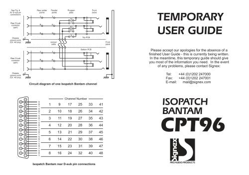
See Fig. #for D-sub pinconnectionsRear D-subconnector(part)Chassisground point(Ch. 48 only)GRear solderpointsTRSParallelpointsTRSJumpercableProgrampadsT2T1R2R1STop PCBFrontJacksFrontpanelTEMPORARYUSER GUIDERear D-subconnector(part)TRSTRSBottom PCBPlease accept our apologies for the absence of afinished User Guide - this is currently being written.In the meantime, this temporary guide should giveyou most of the information you need. In the eventof any problems, please contact Signex:Chassisground point(Ch. 48 only)GCircuit diagram of one <strong>Isopatch</strong> Bantam channelTel: +44 (0)1202 247000Fax: +44 (0)1202 247001E-mail: mail@signex.com25242322212019181716151413121110987654321SRTSRTSRTSRTSRTSRTSRTSRT12345678910111213141516Channel Number17 2518 2619 2720 2821 2922 3023 3124 3233343536373839404142434445464748ISOPATCHBANTAM<strong>CPT96</strong><strong>Isopatch</strong> Bantam rear D-sub pin connectionsPRO AUDIO PRODUCTS
Half or full normalisingThe <strong>Isopatch</strong> Bantam offers a choice of half or full normalising on every channel. When halfnormalised (sometimes called Sniff and Break), the link between the sockets is broken only when aplug is inserted into the bottom socket (half of the pair of sockets). The top socket can be plugged intowithout breaking the link to the socket below, allowing the signal to be <strong>manual</strong>ly patched into anotherinput whilst still connected to its ‘normal’ destination. This configuration is particularly useful because itallows an output to be split and sent to two inputs simultaneously. In this situation, the ‘normal’ link canstill be broken by simply inserting an unconnected jack plug or patch cord into the bottom socket.When a pair is fully normalised, the link between the sockets is broken when a plug is inserted intoeither the top or bottom socket. This option should be used when an output must not be routed to morethan one input at a time.Half normalFull normalR1T1SHalf normalR1T1SFull normalT2, R2 & ST1, R1 & ST2T2R2R2Normalising a channel on the <strong>Isopatch</strong> BantamSignal TypeTipRingSleeveMono (Unbalanced)SignalGroundProgramming normalisingThe <strong>Isopatch</strong> Bantam is supplied with all sockets isolated(not normalised) but any channel may be easily normalisedby soldering across special ‘program pads’ on the top printed circuit board (PCB). There are fiveprogram pads on each channel and they act like switches - soldering across a program pad is likeclosing a switch. When soldering a program pad, more solder is needed than for a normal jointbecause the solder has to 'bridge' the gap in the pad. When bridged, the joint on the program pad willlook like a bead of solder. Take care not to get solder anywhere else on the PCB as this could cause ashort circuit and possibly damage the equipment connected to the <strong>Isopatch</strong> Bantam. If you have noexperience soldering, then ask your dealer to do this for you. To program normalising on any channel,Mono (Balanced)Stereo (Unbalanced) *Digital (SPDIF)Digital (AES/EBU)+ (Hot)RightSignal+ (Hot)- (Cold)Left- (Cold)GroundGroundGroundGroundBantamJack* Left and right channels may bereversed.Note: Screen is always groundWiring of different signal types to a Bantam Jack