LOCATOR® BAR ATTACHMENT SYSTEM
LOCATOR® BAR ATTACHMENT SYSTEM
LOCATOR® BAR ATTACHMENT SYSTEM
- No tags were found...

Create successful ePaper yourself
Turn your PDF publications into a flip-book with our unique Google optimized e-Paper software.
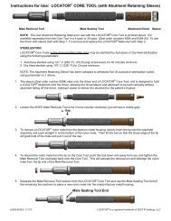
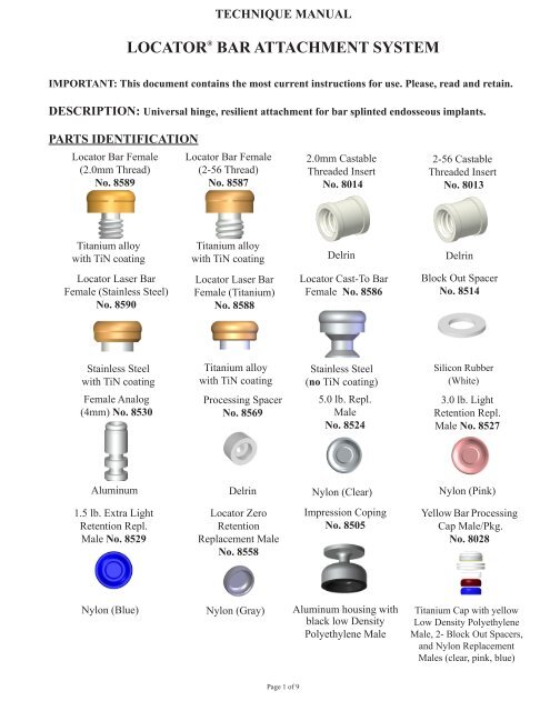
Parallel PostNo. 8517Yellow Bar ProcessingReplacement MaleNo. 8026Locator Core ToolNo. 8393(Male RemovalTool, Male Seating Tool,and Abutment Driver)AbutmentRetaining SleeveNo. 8394Drill & TapHolderNo. 8016Low DensityPolyethylene(Black)Low DensityPolyethylene(Yellow)PolysulfoneLocator ParallelingMandrel No. 910730N-cm Torque Wrench KitNo. 9020 (30N-cm TorqueWrench, 15mm Square DriveInsert and Thumb Knob)1.7mm Bar Drill(2.0mm Thread)No. 91022.0mm Bar Tap(2.0mm Thread)No. 91041.8mm Bar Drill(2-56 Thread)No. 91032-56 Bar Tap(2-56 Thread)No. 9105INDICATIONSThe LOCATOR ® Bar Attachment System is designed for use with overdentures or partial dentures, retainedin whole or in part, by bar splinted endosseous implants in the mandible or maxilla.CONTRAINDICATIONSNot appropriate where a totally rigid connection is required.CAUTIONFederal (U.S.A.) law restricts this device to sale by or on the order of a licensed dentist.SINGLE USE DEVICESLocator Males: The inadvertent re-use of a Locator nylon males could cause loss of retention for theoverdenture due to wear from previous use or damage during removal with the Locator Core Tool.Locator Bar Females: The removal of a Locator Cast-to Bar Female or a Laser Bar Female from afabricated bar could cause damage to both the device and the bar. The inadvertent re-use of a Locator BarFemale could contain patient contamination build-up and subsequent wear of the retention bands. Thiswould result in the device to perform with improper fit and function which would result in loss of retentionfor the prosthesis.STERILIZATIONAll components and instruments are supplied NON-STERILE.Titanium Bar Females may be sterilized by Autoclave or Dry Heat sterilization using the followingparameters:1. Autoclave sterilize using 121° C (250° F), (15-20 psig at sea level), for 20 minutes minimum.2. Dry Heat sterilize using 170° C (338° F) for 2 hours minimum.Locator Core Tools (in the disassembled state only) may be sterilized by Autoclave or Dry Heatsterilization using the following parameters:Page 2 of 9
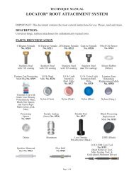
1. Autoclave sterilize using 121º C (250º F), 15-20 psig (at sea level), for 40 minutes minimum.2. Dry Heat sterilize using 170º C (338º F) for 2 hours minimum.FEATURES1. LOWEST VERTICAL HEIGHT: The total height of the Locator Bar Attachment (abutment plusmale) is only 2.5mm on a cast alloy bar.2. LOCATING DESIGN: Self-locating design allows a patient to easily seat their overdenture without theneed for accurate alignment of the attachment components.3. RETENTION INSIDE AND OUT: The patented Dual Retention innovation provides the LocatorAttachment with greater retention surface area than ever before available with other attachments. Acombination of inside and outside retention ensures the longest lasting performance.4. ROTATIONAL PIVOTING ACTION: The design of the pivoting Locator Male allows a resilientconnection for the prosthesis without any resulting loss of retention. The retentive nylon male remainscompletely in contact with the abutment socket while its metal denture cap has a full range of rotationalmovement over the male.5. CHOICE OF FOUR TECHNIQUES: The Locator Bar Attachment can be placed by any of the fourpopular techniques used by Dental Laboratories to fabricate an implant retained bar with attachments:1. Cast a Castable Threaded Insert into a bar for a removable threaded Locator Bar Female connection.2. Drill and tap the bar for a threaded Locator Bar Female.3. Laser weld a Locator Laser Bar Female to the bar.4. Cast-to the stainless steel Locator Cast-To Bar Female with gold alloy.A. PLACEMENT OF THE LOCATOR <strong>BAR</strong> <strong>ATTACHMENT</strong>The Locator Bar Attachment can be placed by any choice of the four following techniques used by a DentalLaboratory to fabricate a bar with dental attachments. CAUTION: The most critical consideration in theproper placement of the Locator Bar Attachment on a milled or cast bar is that a minimum of 1.0mmof bar material remains between the edge of a UCLA type screw retaining the bar and the LocatorBar Female, or a minimum of 5.0mm between the edges of multiple placed Locator Bar Femalesthat is required to avoid interference of the Locator Titanium Denture Caps. (Locator Bar Female =4.0mm Diameter, Locator Denture Cap = 5.5mm Diameter).Technique to cast a Castable Threaded Insert into a bar for a removable threaded Locator Bar Female1. A) Parts needed – New Case:(8014) 2.0mm Castable Threaded Insert(8589) Locator Bar Female (2.0mm Thread)(9104) 2.0mm Bar Tap (2.0mm Thread)(8016) Drill and Tap HolderB) Parts needed – Replace TSB Ball Attachment:(8013) 2-56 Castable Threaded Insert(8587) Locator Bar Female (2-56 Thread)(9105) 2-56 Bar Tap (2-56 Thread)(8016) Drill and Tap Holder2. The 2.0mm Castable Threaded Insert (Zest order No. 8014) and a 2.0mm Bar Tap (Zest order No. 9104)are used for creating the threaded site in a cast alloy bar.Page 3 of 9
3. Survey and set a delrin Castable Threaded Insert into the wax pattern of the bar at each site where aLocator Bar Attachment is needed. The top of the Threaded Insert should be flush with the top surface ofthe surrounding bar pattern.4. The delrin Castable Threaded Insert will become part of the cast alloy bar when the bar pattern is castusing standard casting procedures.5. Insert and tighten the 2.0mm Bar Tap into the Drill & Tap Holder (Zest order No. 8016) and position itinto the handpiece of a precision drilling device. Use the Bar Tap to chase and clean out the cast internalthreads of the attachment site.6. A special Locator Gold-Plated Abutment Driver (attached to the Locator Core Tool, Zest order No.8393) is designed to engage the inside diameter of the threaded Locator Bar Female and thread it intothe bar. A Locator Abutment Retaining Sleeve (Zest order No. 8394) slips onto the Abutment Driver tohold the Locator Bar Female while delivering it to the threaded site in the bar.7. Final torque tightening of the Locator Bar Female to prevent screw loosening is achieved using the30Ncm Torque Wrench (Zest order No. 9020 Kit). In addition, Locator Torque Wrench Drivers that fitdirectly into the Locator Bar Female are available for most brands of torque wrenches.Technique to drill and tap a bar for a removable threaded Locator Bar Female1. A) Parts needed – New Case:(8589) Locator Bar Female (2.0mm Thread)(9102) 1.7mm Bar Drill (2.0mm Thread)(9104) 2.0mm Bar Tap (2.0mm Thread)(8016) Drill & Tap HolderB) Parts needed – Replace TSB Ball Attachment:(8587) Locator Bar Female (2-56 Thread)(9103) 1.8mm Bar Drill (2-56 Thread)(9105) 2-56 Bar Tap (2-56 Thread)(8016) Drill & Tap Holder2. The 1.7mm Bar Drill (Zest order No. 9102) and a 2.0mm Bar Tap (Zest order No. 9104) are used forcreating the threaded site in a titanium bar or cast alloy bar. First use a round carbide bur to create adimple into the top of the bar at the exact site of the planned preparation.3. Insert and tighten the 1.7mm Bar Drill into the Drill & Tap Holder (Zest order No. 8016) and positionit into the handpiece of a precision drilling device. Use the 1.7mm Bar Drill to create the exact sizediameter hole to a depth of 2.8mm that is needed for tapping the site.4. Place the 2.0mm Bar Tap into the Drill & Tap Holder and position it into the handpiece of a precisiondrilling device to create internal threads within the drilled site. The use of tapping fluid while cuttingthe threads is required to reduce the chance of breaking the tap off in the preparation.5. A special Locator Gold-Plated Abutment Driver (attached to the Locator Core Tool, Zest order No.8393) is designed to engage the inside diameter of the threaded Locator Bar Female and thread it intothe bar. A Locator Abutment Retaining Sleeve (Zest order No. 8394) slips onto the Abutment Driver tohold the Locator Bar Female while delivering it to the threaded site in the bar.6. Final torque tightening of the Locator Bar Female to prevent screw loosening is achieved using the30Ncm Torque Wrench (Zest order No. 9020 Kit). In addition, Locator Torque Wrench Drivers that fitdirectly into the Locator Bar Female are available for most brands of torque wrenches.Technique to laser weld a Locator Laser Bar Female on top of a bar1. A) Parts needed – Laser welding to a titanium bar:(8588) Locator Laser Bar Female (Titanium)(9107) Locator Paralleling MandrelB) Parts needed – Laser welding to a cast gold alloy bar:(8590) Locator Laser Bar Female (Stainless Steel)(9107) Locator Paralleling MandrelPage 4 of 9
11. Divesting. After casting, allow the casting to bench cool for 20 minutes. Be careful to push out thecasting and investment with proper tools. It is not recommended to hammer or bang on rings that maydistort the castings. To remove the investment material from the Cast-To Bar Female without damage tothe stainless steel, use an acid-free investment and porcelain remover solution in an ultrasonic unit for aperiod of 30-45 minutes. (Do not use a bur to remove the investment, sandblasting with aluminumoxide, or an acid pickling solution, all of which can damage the retention surfaces of the BarFemale attachment.) Clean the bar containing the Locator Cast-To attachment in an ultrasonic cleanersolution.12. Finishing and Polishing. When polishing with a rubber wheel, use caution not to damage the Cast-ToBar Female attachment. Polish the surface of the bar to make a smooth surface. The Locator ParallelPost (Zest order No. 8517) can be placed on the female to protect the attachment while polishing. [Ifadditional polishing of the female attachment is required, it is recommended to only use glass beads at alow pressure (40 PSI) or a fiberglass or bristle polishing brush.]13. After polishing the bar, place a Locator Denture Cap Yellow Processing Male Assembly (contained inZest order No. 8028 package) onto each Cast-To Bar Female and check for proper fit. Clean again in anultrasonic solution and deliver to the dental office.B. LOCATOR DENTURE CAP MALE PLACEMENT BY THE DENTIST1. Placement of the desired type of Locator Bar Female into the bar (see Section A) and delivery of the barto the patient must be completed before beginning the procedure for placement of the Locator DentureCap Yellow Processing Male Assembly.2. Place a White Block-Out Spacer (contained in Zest order No. 8028 Package) over the head of eachLocator Bar Female. The spacer is used to block out the area immediately surrounding the attachment.The space created will allow the full resilient function of the pivoting metal denture cap over the LocatorNylon Male.NOTE: Due to the additional height required for the Laser Bar Females (Zest order No. 8588and No. 8590), they require the use of 2 White Block-Out Spacers stacked on top of each otherfor proper block out. It is also necessary to block out all undercuts beneath the bar to prevent theadded acrylic resin from locking the denture onto the bar.3. Insert a Locator Denture Cap Yellow Processing Male Assembly (contained in Zest order No. 8028Package) onto each Locator Bar Female, leaving the White Block-Out Spacer beneath it. The LocatorYellow Bar Processing Replacement Male will maintain the overdenture in the upper limit of its verticalresiliency during the processing procedure.4. Prepare a recess in the denture to accommodate the protruding Locator Denture Cap Yellow ProcessingMale Assembly. There must be no contact between the denture and the titanium cap. If the denture restson the metal cap, excess pressure on the implant will result.5. Use the Chairside Dental Attachment Light Cure Kit (Zest order No. 9403) to light cure bond theLocator Denture Cap Yellow Processing Male Assembly into the denture, or mix a permanent self-curingacrylic and place a small amount in the recess of the denture and around the metal cap of the LocatorDenture Cap Yellow Processing Male Assembly.6. Insert the denture into position in the oral cavity. Guide the patient into occlusion, maintaining aproper relationship with the opposing arch. Maintain the denture in a passive condition, withoutcompression of the soft tissue, while the acrylic sets. Excessive occlusal pressure during the settingtime may cause tissue recoil against the denture base and could contribute to dislodging and wearof the nylon males.7. After the acrylic resin has cured, remove the denture and discard the White Block-Out Spacer. Use a burto remove excess acrylic, and polish the denture base before changing to the appropriate Locator NylonReplacement Male.Page 6 of 9
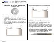
NOTE: If the dentist prefers to do a chairside pickup of the Locator Denture Cap YellowProcessing Male Assembly, use of the Locator Processing Spacer (Zest order No. 8569) will createthe exact space needed.10. Complete the processing and discard the White Block-Out Spacer. Polish the denture base beforechanging to the appropriate Locator Nylon Replacement Male.11. Use the Locator Male Removal Tool (attached to the Locator Core Tool, Zest order No. 8393) to removethe Yellow Bar Processing Replacement Male from the metal Denture Cap. The sharp circular edgeon the end of the removal tool should be wedged tightly down into the very bottom of the Yellow BarProcessing Replacement Male so that it will catch the inside of the male and pull it at an angle out of themetal housing.12. The Locator Male Seating Tool (attached to the Locator Core Tool, Zest order No. 8393) is used tofirmly push a Locator Replacement Male into the empty metal Denture Cap. The Replacement Malemust seat securely into place, level with the rim of the cap. Use of multiple Locator attachments (3or more) in the same dental arch may require use of the 1.5 lbs. (extra light retention) blue coloredReplacement Male No. 8529 in combination with 0.0 lbs. (non-retentive) gray colored ReplacementMale No. 8558, for easier removal of the prosthesis by the patient.NOTE: The Replacement Male will not stay on the tool when it is turned upside down due to thevarying sizes of males available. It is best to hold the denture with the base side down and snap themale into the metal Denture Cap.D. HOW TO CHANGE THE LOCATOR MALE1. The Locator Core Tool, (Zest order No. 8393) which contains a Locator Male Removal Tool and LocatorMale Seating Tool is used to remove the Nylon Male from the metal Denture Cap and replace it with aLocator Replacement Male.2. Use the Male Removal Tool attached to the Locator Core Tool to remove the Nylon Male from the metalDenture Cap. The sharp circular edge on the end of the removal tool should be wedged tightly down intothe very bottom of the Nylon Male so that it will catch the inside of the male and pull it at an angle outof the metal housing. To discard the Nylon Male from the tip on the Core Tool, point the tool down andaway from you and tighten the Male Removal Tool clockwise back onto the Core Tool. This will activatethe Removal Pin and dislodge the Nylon Male from the tip end of the Male Removal Tool.3. The Locator Male Seating Tool is used to firmly push a Locator Replacement Male into the empty metaldenture cap. The replacement male must seat securely into place, level with the rim of the cap.NOTE: The Replacement Male will not stay on the tool when it is turned upside down due to thevarying sizes of males available. It is best to hold the denture with the base side down and snap themale into the metal Denture Cap.E. RELINE AND REBASE1. Remove each existing Nylon Male from its metal Denture Cap following the steps in HOW TOCHANGE THE LOCATOR MALE (Section D). Replace them with Yellow Bar Processing ReplacementMales (Zest order No. 8026). The built-in spacer of the Yellow Bar Processing Replacement Male willmaintain the overdenture in the same position on the bar as with the original processing, during thereline process.2. Take a reline impression using the existing overdenture as a tray.Page 8 of 9