Download Inpro OUF-88 Oil Lifter Installation Manual ... - Oilybits.com
Download Inpro OUF-88 Oil Lifter Installation Manual ... - Oilybits.com
Download Inpro OUF-88 Oil Lifter Installation Manual ... - Oilybits.com
- No tags were found...

Create successful ePaper yourself
Turn your PDF publications into a flip-book with our unique Google optimized e-Paper software.
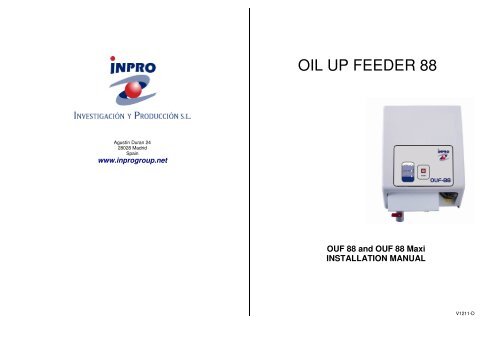
OIL UP FEEDER <strong>88</strong>Agustín Duran 2428028 MadridSpainwww.inprogroup.net<strong>OUF</strong> <strong>88</strong> and <strong>OUF</strong> <strong>88</strong> MaxiINSTALLATION MANUALV1211-D
Display quick reference listNormal Operation Status:Fix light: Flashing Light:<strong>OUF</strong> <strong>88</strong> <strong>Oil</strong> <strong>Lifter</strong> is powered. Pump filling No Power Supply<strong>Oil</strong> in lifter reservoir arrived till stop level. <strong>OUF</strong> reservoirIt keeps this state till low level is reachedagain, or start button is pushed.Alarm Status:Very high level is reached Very low level is reached Leak detection(optional)Leak detection (optional) No oil Safety Stop: No level probe is detectedCombined with low level alarm Activated after 1 hourapprox. running without oilOther Status:1x 5…Reset SequenceAutomatic Start Mode facilityFollowing to an interruption to the power To enter, keep pressing start button duringautomatically starts within 3 seconds. 5 green led blinks (5 sec approx) 10
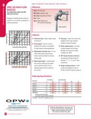
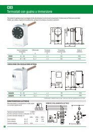
Accessories:<strong>Oil</strong> tray with leak detectionsystemAn oil tray with an infrared leakdetection system is available foryour <strong>OUF</strong>.This optional oil tray is stronglyre<strong>com</strong>mended, particularly in theevent that the overflow pipe isnot connected.In some regions, the use of theoil tray can be <strong>com</strong>pulsory undercertain local standards. Please askyour dealer for details.How does the leak detection system functionOnce installed, the function of your <strong>OUF</strong> remains unchanged,except when some liquid at the infrared probe activates thesystem. At that moment:- The pump stops- The upper led “high level” starts blinkingThis status will be maintained until the infrared probe is<strong>com</strong>pletely clean and dry again and the start button is pressedagain.INDEX<strong>OUF</strong> <strong>88</strong> <strong>Installation</strong> 3Troubleshooting and maintenance 4Wiring Diagram 5System description and parts 6<strong>Installation</strong> examples 7<strong>OUF</strong><strong>88</strong> Technical Specifications 8Accessories 9Display quick reference list 10<strong>Installation</strong> of the leak detectionsystem:1.- Be sure that the <strong>OUF</strong><strong>88</strong> unit is notpowered2.- Extract the jumper at the circuiton the lower side3.- Connect the probe connector4.- Place the infrared sensor in theblue clip in the oil tray, at the lowestpossible position5.- Extract the yellow cap at overflowoutlet92
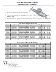
<strong>OUF</strong> <strong>88</strong> ISTALLATIO<strong>Installation</strong> must be in accordance with BS 5410 + anylocal building regulations1/ Connect the suction line from the main tank to the ‘inlet’ andthe supply pipe (‘gravity fed’) to the appliance to the outlet.Connect the overflow facility(*).2/ Connect the <strong>OUF</strong> <strong>88</strong> to the mains supply either through aplug (not included) or fused electric spur (see attached wiringdiagram).The mains supply cable has to pass trough the access hole tothe back part of the mounting plateOnce powered up the low level led light will <strong>com</strong>e on.3/ To start the <strong>OUF</strong> automatic operation, press and keeppressed the start button, which will start the pump, filling the<strong>OUF</strong> <strong>88</strong> reservoir, until the Low Level lamp turns off.The pump may be noisy initially until the fuel starts <strong>com</strong>ingthrough to the pump.Automatic start mode: If you keep pressed the start button during the 5seconds just after the power supply is connected to your pump, you enter ina special programmed mode which keeps triggered the start button tillautomatic mode is reached (low level, so the pump continues filling <strong>OUF</strong>reservoir till high level). You will identify if you are under this mode becausethe 2 lower leds keep flashing intermittently. See details at page 10Once reached the low level, you can release the start button,because the <strong>OUF</strong> works in automatic mode.4/ Once the oil has filled the <strong>OUF</strong> <strong>88</strong> reservoir to theprogrammed maximum level (80% approx), the working levelswitch will stop the pump.5/ The <strong>OUF</strong> is now ready for use and the appliance(s) can beused. The <strong>OUF</strong> <strong>88</strong> will manage the fuel supply automatically.(*) The overflow connection is dual purpose:1) It must be connected with a return pipe to the tank as a safety feature in theevent that the float switch fails. A leak detector & oil tray are available as analternative if it is not possible to take the overflow back to the tank. Themanufacturer will refuse any liability for damages at any installation without atleast one these two additional safety options fitted.2) It can be connected to the oil tank to allow venting of the <strong>OUF</strong><strong>88</strong> reservoir if itis required to be sealed to prevent unwanted smells.3PUMP TYPE<strong>OUF</strong> <strong>88</strong> – TECHNICAL SPECIFICATIONSLIFTING HEIGHT (MAX.)MÁX. HORIZONTALDISTANCEOUTLET FLOW RATING(8 mm I.D. tube)INLET CONNECTIONOUTLET CONNECTIONOVERFLOW OUTLETCONNECTIONPOWER SUPPLYPOWER CONSUMPTIONRESERVOIR TOTALCAPACITYWidth:DIMENSIONS: Depth:Height:Suction Solenoid Pump8 m vertical (8 mm I.D. tube)100 m horizontal (8 mm I.D.. tube)8 L/hr at: 8 m vertical & 25 m horizontal15 l/hr at: 5 m vertical & 25 m horizontal3/8 " F BSP3/8 " F BSP½ " F BSPAC 230V, 50Hz50 W3,5 Litre. 12 Litre<strong>OUF</strong> <strong>88</strong>(240 mm)(130 mm)(335 mm)<strong>OUF</strong> <strong>88</strong> MAXI(350 mm)(225 mm)(345 mm)WEIGHT 3 kg 4 kgFUEL TYPE Kerosene & Diesel <strong>Oil</strong>8
<strong>Installation</strong> examples:If under automatic function, the noise level is not low andstable, that will mean that you have air <strong>com</strong>ing inside the pump:Check suction line vacuum tightness, tube size, and distancesrelated to suction limits of your <strong>OUF</strong> <strong>88</strong>.If the oil does not <strong>com</strong>e up to the <strong>OUF</strong> <strong>88</strong>:- Check suction pipe for blockage and/or vacuum tightness.- Is your vertical lift height lower than 8 mt?- Check if the filter is clogged/dirtyIf the problem still persists:- Check pump suction power (with a vacuum gauge orby placing your hand at the filter inlet and pressing thestart button to see if you can feel suction.- Check power supply voltage- Prime the suction line at the <strong>OUF</strong> <strong>88</strong>. Then switch onthe pump to pull this oil through and the oil from thetank.- Check if there is oil at main tank. After 1 hourpumping without oil, the pump will stop itself.Do not install below oil level at maintank, as siphoning may occur if noextra device is installed (anti siphonvalve or NC solenoid valve)For outdoor use, use a weatherproofprotective cabinet for the <strong>OUF</strong>-<strong>88</strong>Important:Maintenance:- Clean regularly the filter bowl and strainer.Suction curve:74
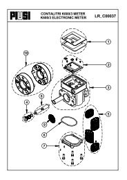
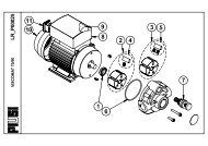
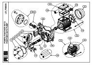
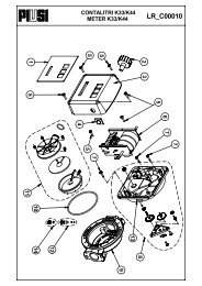
<strong>OUF</strong> <strong>88</strong> Wiring Diagram5 Warning: Make sure that ground isproperly connected. Not connecting it, orhaving a defective earthing, may start thereset sequence too often.PART DESCRIPTIONArt. Nr.1. FILTER 3/8 " BSP/ INLET CONNECTION 011100020040102. PUMP 010000000046603. OVERFLOW 1/2 " BSP CONNECTION -4. FLOAT SWITCH PROBE 23130000032010REPLACEMENT FLOAT IN STAINLESS STEEL 002300041541355. OIL RESERVOIR (3 lts) or (MAXI 12 lts.)) -6. OUTLET CONNECTION 3/8 " BSP 010500003801677. POWER SUPPLY ACCESS HOLE -8. LEAK DETECTION PROBE SYSTEM CONNECTOR 031500000340009.- <strong>OUF</strong> CONTROL CIRCUIT COMPLETE (Ver. D: control and filter) 2311000000031010.- INFRARRED PROBE FOR <strong>OUF</strong> <strong>88</strong>, 350 mm long 2308000000001011.- PROBE AND OIL TRAY 310x200x60mm FOR <strong>OUF</strong> <strong>88</strong> 2309000000103512.- TRANSPARENT PIPE 0112000009080513.- 1 SIDE COMPRESSED CLIPS 7.8/9.5 050800000002086