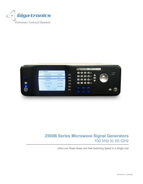
2500B Series Microwave Signal Generators 100 kHz to 50 GHz
2500B Series Microwave Signal Generators 100 kHz to 50 GHz
2500B Series Microwave Signal Generators 100 kHz to 50 GHz
- No tags were found...
Create successful ePaper yourself
Turn your PDF publications into a flip-book with our unique Google optimized e-Paper software.
<strong>2<strong>50</strong>0B</strong> <strong>Series</strong> <strong>Microwave</strong> <strong>Signal</strong> Genera<strong>to</strong>r<strong>Signal</strong> Genera<strong>to</strong>r Frequency RangeThe <strong>2<strong>50</strong>0B</strong> series <strong>Microwave</strong> <strong>Signal</strong> <strong>Genera<strong>to</strong>rs</strong> include six models covering <strong>100</strong> <strong>kHz</strong> <strong>to</strong> <strong>50</strong> <strong>GHz</strong>.Model Number Frequency Range RF Output Connec<strong>to</strong>r2<strong>50</strong>2B <strong>100</strong> <strong>kHz</strong> <strong>to</strong> 2.5 <strong>GHz</strong> Type-N (F)2<strong>50</strong>8B 2 <strong>GHz</strong> <strong>to</strong> 8 <strong>GHz</strong> Type-N (F)2520B 2 <strong>GHz</strong> <strong>to</strong> 20 <strong>GHz</strong> SMA (F)2526B 2 <strong>GHz</strong> <strong>to</strong> 26.5 <strong>GHz</strong> SMA (F)2540B 2 <strong>GHz</strong> <strong>to</strong> 40 <strong>GHz</strong> 2.92 mm (F)25<strong>50</strong>B 2 <strong>GHz</strong> <strong>to</strong> <strong>50</strong> <strong>GHz</strong> 2.4 mm (F)Available OptionsOption17A17BDescriptionAdd Internal and External Modulation Suite (includes internal function genera<strong>to</strong>r)Add External Modulation Suite18 Add <strong>100</strong> <strong>kHz</strong> <strong>to</strong> 2 <strong>GHz</strong> Frequency Range(Standard on the 2<strong>50</strong>2B model)22 Add Rear Panel RF Output Connec<strong>to</strong>r23 Add Type-N RF Connec<strong>to</strong>r, for 2520B only26AAdd 90 dB Mechanical Step Attenua<strong>to</strong>r, for 2<strong>50</strong>2B, 2<strong>50</strong>8B, and 2520B models26BAdd 90 dB Mechanical Step Attenua<strong>to</strong>r, for 2526B model only26CAdd 90 dB Mechanical Step Attenua<strong>to</strong>r, for 2540B model only26DAdd 90 dB Mechanical Step Attenua<strong>to</strong>r, for 25<strong>50</strong>B model only27 Add 110 dB Electronic Step Attenua<strong>to</strong>r, for 2<strong>50</strong>2B and 2<strong>50</strong>8B only28 Add Ultra-Low Close-In Phase Noise31 Add Switching Speed > 2 ms and Pulse Width > <strong>100</strong> ns43 Add Analog Sweep44 Replace Standard Front Panel with Blank Front Panel (Requires Option 22)46 Add Rack Slide Kit55XAdd Emulation Command Set (See ordering information for detail)The new <strong>2<strong>50</strong>0B</strong> series now give you more options <strong>to</strong> configure the <strong>Microwave</strong> <strong>Signal</strong> Genera<strong>to</strong>r <strong>to</strong> your specific application, while still loaded withstandard features such as high stability time base and high leveled output power with low harmonics.134794-Rev.A / US090622
Au<strong>to</strong>mation Xpress InterfaceThe <strong>2<strong>50</strong>0B</strong> <strong>Series</strong> offers unmatched frequency and power switching in list mode. However, this approach may not be suitable in some remoteprogramming situations. For these cases, Au<strong>to</strong>mation Xpress offers fast remote operation that goes beyond just fast frequency switching.Au<strong>to</strong>mation Xpress ensures unmatched CW frequency and power switching performance, providing fast and flexible data exchange rates for fastertesting and more device throughput.Simpler <strong>to</strong> OperateThe <strong>2<strong>50</strong>0B</strong> <strong>Series</strong> is designed <strong>to</strong> streamline user navigation by moving complex testing functions from the front panel <strong>to</strong> the desk<strong>to</strong>p PC. Theresult is a ground breaking system that reduces training time, speeds workflow, and dramatically boosts end-user productivity. To enhance usernavigation, we minimized the number of soft screens and menu layers, simplifying content and improving operational performance. That meansyou will spend less time scrolling through data menus and more time getting your work done.Optimized for ATEWith the <strong>2<strong>50</strong>0B</strong> <strong>Series</strong>, ATE integra<strong>to</strong>rs now have a system source specifically designed <strong>to</strong> match their unique performance needs. The <strong>2<strong>50</strong>0B</strong><strong>Series</strong> works seamlessly with other instruments. It includes hardware triggering and synchronization signals with programmable delays <strong>to</strong> allowcoordination with other test products in your system. Replacing older industry-standard microwave synthesizers can also be accommodated,making the <strong>2<strong>50</strong>0B</strong> <strong>Series</strong> an ideal choice for upgrading older systems.CompatibilityThe <strong>2<strong>50</strong>0B</strong> <strong>Series</strong> unit has full command compatibility with the 2400 <strong>Series</strong> and previous generation signal genera<strong>to</strong>rs from Giga-tronics. Inaddition, Giga-tronics offers optional command sets for the legacy signal genera<strong>to</strong>rs offered by other manufacturers allowing cus<strong>to</strong>mers <strong>to</strong> replaceall the legacy signal genera<strong>to</strong>rs with a single unit from Giga-tronics.Two Year Calibration CycleA two-year calibration cycle significantly reduces your calibration downtime.334794-Rev.A / US090622
Giga‐tronics 2<strong>50</strong>0 <strong>Series</strong> Switching Speed vs. FrequencyChange (Typical)800Switching Spee ed (uS)700600<strong>50</strong>0400300200Up from 4Up <strong>to</strong> 10Down <strong>to</strong> 4Down from 1034794-Rev.A / US090622<strong>100</strong>00.001 0.01 0.1 1 10Frequency Change (<strong>GHz</strong>)7
List ModeNumber of Points 4000Frequency Settling 12Amplitude Settling 14 < <strong>50</strong>0 µsDigital SweepStep TimeSync Out Delay 15< 5<strong>50</strong> µs for ∆F ≤ <strong>50</strong>0 MHzTrigger ModesSweep ModesStandardOption 31<strong>50</strong> µs - 10 msExternal, GPIB GET, SoftwareContinuous, Single Step, Single Sweep1<strong>50</strong> µsec - 1 sec2 msec - 1 secRemote ProgrammingHardware InterfaceSoftware InterfaceExecution Speed (IEEE 488.2)Au<strong>to</strong>mation XpressRemote InterfaceIEEE 488.2, RS-232, USB 2.0 (full speed, not high speed), EthernetSCPI, GT12000, GT9000, GT900, Au<strong>to</strong>mation Xpress Interface (Standard)AXISCPICW Switching (typ) 2.5 ms 28 ms4000 Point List Download (typ) 20 sec 28 sec20 MB Disk SpaceGPIB (IEEE 488.2, 1987) with listen and talk RS-23212Time for frequency <strong>to</strong> settle within <strong>50</strong> <strong>kHz</strong> of final value after a frequency switch13Time for amplitude <strong>to</strong> settle within 0.1 dB of final value after an amplitude switch14 Delay is specified from edge of trigger pulse834794-Rev.A / US090622
Spectral PurityHarmonicsSub-HarmonicsSpuriousResidual FM (typical)AM Noise (typical)Maximum leveled output power or +10 dBm, whichever is lower. Specification for harmonics above instrumentfrequency range are typical<strong>100</strong> <strong>kHz</strong> <strong>to</strong> 10 MHz -30 dBc> 10 MHz <strong>to</strong> <strong>100</strong> MHz -40 dBc> <strong>100</strong> MHz <strong>to</strong> 39.6 <strong>GHz</strong> 15 -<strong>50</strong> dBc> 39.6 <strong>to</strong> <strong>50</strong> <strong>GHz</strong> -30 dBc (typical)Maximum leveled output power or +10 dBm, whichever is lower. Specification for sub-harmonics above instrumentfrequency range are typical<strong>100</strong> <strong>kHz</strong> <strong>to</strong> 2.0 <strong>GHz</strong> -80 dBc> 2 <strong>to</strong> 20.2 <strong>GHz</strong> -60 dBc> 20.2 <strong>to</strong> <strong>50</strong> <strong>GHz</strong> -40 dBcSpecification is for offsets > 300 Hz.Specification is -45 dBc + 20 log(1/N) dBc typical for offsets < 300 Hz<strong>100</strong> <strong>kHz</strong> <strong>to</strong> 10.1 <strong>GHz</strong> -65 dBc> 10.1 <strong>to</strong> 20.2 <strong>GHz</strong> -58 dBc> 20.2 <strong>to</strong> 39.6 <strong>GHz</strong> -<strong>50</strong> dBc> 39.6 <strong>to</strong> <strong>50</strong> <strong>GHz</strong> -40 dBc<strong>50</strong> Hz <strong>to</strong> 15 <strong>kHz</strong> Bandwidth<strong>100</strong> <strong>kHz</strong> <strong>to</strong> 20.2 <strong>GHz</strong> < 6 Hz> 20.2 <strong>to</strong> 39.6 <strong>GHz</strong> 16 < 12 Hz> 39.6 <strong>to</strong> <strong>50</strong> <strong>GHz</strong> < 18 HzOffset > 5 MHz at maximum leveled power<strong>100</strong> <strong>kHz</strong> <strong>to</strong> 2 <strong>GHz</strong> -130 dBm/Hz> 2 <strong>to</strong> 20.2 <strong>GHz</strong> -145 dBm/Hz> 20.2 <strong>to</strong> <strong>50</strong> <strong>GHz</strong> -132 dBm/HzSSB Phase Noise - StandardCarrierCW (<strong>GHz</strong>) <strong>100</strong> Hz 1 <strong>kHz</strong> 10 <strong>kHz</strong> <strong>100</strong> <strong>kHz</strong> 1 MHz1.0 -96 -109 -124 -124 -1<strong>50</strong>4.0 -84 -94 -114 -112 -14210.0 -77 -96 -109 -108 -13820.0 -71 -88 -102 -102 -12630.0 -67 -79 -99 -99 -12734794-Rev.A / US090622915,16 Specification for model 2540B extends <strong>to</strong> 40 <strong>GHz</strong>
SSB Phase Noise - Option 28CarrierOffset from Carrier (dBc/Hz)CW (<strong>GHz</strong>) 1 Hz 10 Hz <strong>100</strong> Hz 1 <strong>kHz</strong> 10 <strong>kHz</strong> <strong>100</strong> <strong>kHz</strong> 1 MHz1.0 -55 -83 -106 -118 -124 -124 -1<strong>50</strong>4.0 -43 -71 -94 -108 -114 -112 -14210.0 -35 -63 -86 -<strong>100</strong> -109 -108 -13820.0 -29 -57 -80 -94 -102 -102 -12630.0 -23 -51 -74 -88 -99 -99 -12734794-Rev.A / US09062210
Amplitude Modulation 17(Specification applies for frequencies above 10 MHz)Depth0 <strong>to</strong> 90% (Level = 0 dBm)Rate (3 dB Bandwidth at carrier level of 0 dBm) DC <strong>to</strong> <strong>100</strong> <strong>kHz</strong> (Depth = <strong>50</strong>%)SensitivityAccuracyInput0 <strong>to</strong> 95% per Volt, selectable± 10% of setting at 1 <strong>kHz</strong> rateRangeImpedance± 1V600 ΩFrequency Modulation 18(Specification applies for frequencies above 10 MHz)Low RateHigh RateModulation IndexRate ( 3 dB bandwidth)Peak DeviationAccuracyInput RangeInput ImpedanceDeviation LimitedDC - 7<strong>50</strong> <strong>kHz</strong>1.5 MHz/N± 5% at 5 <strong>kHz</strong> rate with 1 V peak input, 12.024 <strong>kHz</strong>/V sensitivity± 1V<strong>50</strong> ΩModulation Index < 25/NRate (3 dB bandwidth)Peak DeviationAccuracyInput RangeInput ImpedancePhase Modulation(Specification applies for frequencies above 10 MHz)Rate (3 dB Bandwidth)Peak DeviationAccuracy<strong>100</strong> Hz <strong>to</strong> <strong>100</strong> <strong>kHz</strong>10 rad-pk/N7<strong>50</strong> <strong>kHz</strong> <strong>to</strong> 5 MHz15 MHz/N± 5% at 1 MHz rate with 1 V peak input , 2.4048 MHz/V sensitivity± 1V<strong>50</strong> Ω± 5% at 1 <strong>kHz</strong> rate with 1 V peak input, 3.83 rad-pk/V sensitivity34794-Rev.A / US09062211Pulse Modulation(Specification applies for frequencies above <strong>50</strong>0 MHz)Standard Operating ModesOn/Off RatioRise/Fall TimesInternal, External> 80 dB0.5 - 20 <strong>GHz</strong> < 10 ns max, 3 ns typ.20 - <strong>50</strong> <strong>GHz</strong> < 25 ns max, 10 ns typ.Minimum Leveled Pulse Width Internal / External 3<strong>50</strong> nsMinimum Unleveled Pulse Width Open-Loop Calibrated 25 nsLevel Accuracy 19 Pulse Width > <strong>100</strong> - 3<strong>50</strong> ns+ 1.5 / - 0.5 dBPulse Width > 3<strong>50</strong> ns ± 0.5 dBPRF (<strong>50</strong>% Duty Cycle)Pulse Width > 25 - <strong>100</strong> nsLeveledOpen-Loop Calibrated+ 2.5 / - 0.5 dB< 3 MHz< 10 MHz0.5 - 2 <strong>GHz</strong>: < 5%Video Feed Through2 - <strong>50</strong> <strong>GHz</strong>: < 1%Pulse FidelityCompression< ± 5 nsRF Delay< 75 nsInput Sensitivity TTL levels (polarity selectable)17Modulation peaks must be less than maximum available power18Settling time not specified with FM turned on19 Duty Cycle must be >0.01%
Internal Function Genera<strong>to</strong>rAM Modulation SourceWaveformsRateResolutionAccuracySine, Square, Triangle, Ramp, Gaussian Noise0.01 Hz <strong>to</strong> <strong>100</strong> <strong>kHz</strong>, all waveforms0.01 HzSame as time baseAM Out2V, peak <strong>to</strong> peak in<strong>to</strong> 10 kΩ loadWaveformsSine, Square, Triangle, RampRate0.01 Hz <strong>to</strong> 1 MHz, all waveformsFM Modulation and PhaseModulation SourceResolution0.01 HzAccuracySame as time baseFM Out2V, peak <strong>to</strong> peak in<strong>to</strong> 10 kΩ loadPulse Modulation Modes Continuous, Gated, Triggered, Pulse Burst (up <strong>to</strong> 300 pulses)Width10 ns <strong>to</strong> 10 msPulse Repetition0.2 µs <strong>to</strong> 1 secPulse Modulation SourceSync. Out Delay0 <strong>to</strong> 10 msResolution10 nsAccuracy±2% of setting or ±15 ns, whichever is greater. ±0.08% typ.Pulse Mod Out2 V in<strong>to</strong> <strong>50</strong> ΩPhysicalEnvironmental MIL-PRF-28800F. Class 3SafetyWeightEmissionsRack HeightDimensions (with rack handles)PowerEN61010< 35 lbs (15.9 kg)EN613263U (5.25 inches (133.4 mm)19 inches (W) x 21 inches (D) x 5.2 inches (H)90-253 VAC, 47-440 Hz300 Watts typical, 3<strong>50</strong> Watts max.34794-Rev.A / US09062212
<strong>2<strong>50</strong>0B</strong> <strong>Series</strong> Rear Panel I/O Connec<strong>to</strong>r DescriptionsConnec<strong>to</strong>r Label Specifications Connec<strong>to</strong>r TypeEXT ALC External ALC Input BNCRF OUT Rear Panel Output, option 22only SMA, N, 2.92 mm or2.4 mmFM OUT Internal modulation genera<strong>to</strong>r output; 2 Vp-p in<strong>to</strong> 10 kΩ BNCPULSE OUT A +4 V video representation of the pulsed RF output signal BNCAM OUT Internal modulation genera<strong>to</strong>r output; 2 Vp-p in<strong>to</strong> 10 kΩ BNCPM SYNC OUT Synchronization output pulse width > 75 nsec width BNCFM IN <strong>50</strong> Ω BNCAM IN 600 Ω BNCPULSE IN/PM TRIG N11 +5 V, <strong>50</strong> Ω BNCLOCK/LEVEL +5 V indica<strong>to</strong>r for phase/level lock for CW mode and in list mode BNCREF TUNE 0 <strong>to</strong> +10 V BNCSYNC OUT +5 V output pulse BNCTRIGGER IN Used <strong>to</strong> trigger a list. Accepts a TTL level signal of > <strong>50</strong> nsec width. BNCBLANKING +5 V output indica<strong>to</strong>r for band crossing, filter switching, and retraces BNCRAMP OUT 0 <strong>to</strong> 10 V BNCSTOP SWP IN/OUT 5 V, 2 kΩ, active low BNCV/<strong>GHz</strong> 0.5 V (2<strong>50</strong>2, 2<strong>50</strong>8, 2520) 0.25 V (2526, 2540, 25<strong>50</strong>) BNC<strong>100</strong> MHz OUT +5 dBm typical, <strong>50</strong> Ω BNC10 MHz OUT 2 Vp-p, <strong>50</strong> Ω BNCEXT REF IN 10 MHz ± <strong>50</strong> Hz ( > -5.0 dBm )/<strong>100</strong> MHz ± <strong>50</strong>0 Hz ( > +5 dBm <strong>to</strong> +8 dBm), <strong>50</strong> Ω BNCGPIB A 24-pin IEEE STD 488.2 connec<strong>to</strong>r for control of the instrument during remote operation using GPIB Type 57RS-232 A DB-9 connec<strong>to</strong>r for control of the instrument during remote operation using RS-232 serial communications DB-9USB USB 2.0 (Device) for control of the instrument during remote operation using USB communications USB type BLAN <strong>100</strong> Base T Ethernet for control of the instrument during remote operation using Ethernet RJ45AC POWER INPUT 90-253 VAC, au<strong>to</strong>-sensing, 47 Hz <strong>to</strong> 440 Hz IEC Power Line34794-Rev.A / US09062213
Ordering InformationGiga-tronics has a network of RF and <strong>Microwave</strong> instrumentation sales engineers and a staff of fac<strong>to</strong>ry support personnel <strong>to</strong> help you find the best, most economicalinstrument for your specific applications. In addition <strong>to</strong> helping you select the best instrument for your needs, our staff can provide quotations, assist you in placingorders, and do everything necessary <strong>to</strong> ensure that your business transactions with Giga-tronics are handled efficiently.Model Number2<strong>50</strong>2B2<strong>50</strong>8B2520B2526B2540B25<strong>50</strong>BFrequency Range<strong>100</strong> <strong>kHz</strong> <strong>to</strong> 2.5 <strong>GHz</strong>2 <strong>GHz</strong> <strong>to</strong> 8 <strong>GHz</strong>2 <strong>GHz</strong> <strong>to</strong> 20 <strong>GHz</strong>2 <strong>GHz</strong> <strong>to</strong> 26.5 <strong>GHz</strong>2 <strong>GHz</strong> <strong>to</strong> 40 <strong>GHz</strong>2 <strong>GHz</strong> <strong>to</strong> <strong>50</strong> <strong>GHz</strong>Available Options and AccessoriesOption Description17AAdd Internal and External Modulation Suite (includes internal function genera<strong>to</strong>r)17BAdd External Modulation Suite18 Add <strong>100</strong> <strong>kHz</strong> <strong>to</strong> 2 <strong>GHz</strong> Frequency Range (Standard on the 2<strong>50</strong>2B model)22 Add Rear Panel RF Output Connec<strong>to</strong>r23 Add Type-N RF Connec<strong>to</strong>r, for 2520B only26AAdd 90 dB Mechanical Step Attenua<strong>to</strong>r, for 2<strong>50</strong>2B, 2<strong>50</strong>8B, and 2520B models26BAdd 90 dB Mechanical Step Attenua<strong>to</strong>r, for 2526B model only26CAdd 90 dB Mechanical Step Attenua<strong>to</strong>r, for 2540B model only26DAdd 90 dB Mechanical Step Attenua<strong>to</strong>r, for 25<strong>50</strong>B model only27 Add 110 dB Electronic Step Attenua<strong>to</strong>r, for 2<strong>50</strong>2B and 2<strong>50</strong>8B only28 Add Ultra-Low Close-In Phase Noise31 Add Switching Speed > 2 ms and Pulse Width > <strong>100</strong> ns43 Add Analog Sweep44 Replace Standard Front Panel with Blank Front Panel (Requires Option 22)46 Add Rack Slide Kit55AHP 8370 Emulation Command Set55BHP 8340 Emulation Command Set55CHP 8673C/D Emulation Command Set55DHP 8663A Emulation Command Set55ESystron Donner 1720 Emulation Command Set55FWavetek 90X Emulation Command Set55GHP 83<strong>50</strong> Emulation Command Set55HHP 8360 Emulation Command SetGiga-tronics Support ServicesAt Giga-tronics, we understand the challenges you face. Our support services begin from the moment you call us. We help you achieve both <strong>to</strong>p-line growth andbot<strong>to</strong>m-line efficiencies by working <strong>to</strong> identify your precise needs and implement smart and result orientated solutions. We believe and commit ourselves in providingyou with more than our superior test solutions. For technical support, contact:Tel: 1-800-726-GIGA (4442) or (925) 328-4669Email: support@gigatronics.comUpdatesAll data is subject <strong>to</strong> change without notice. For the latest information on Giga-tronics products and applications, please visit:http://www.gigatronics.com34794-Rev.A / US09062214
©2009 Giga-tronics Incorporated. All Rights Reserved. All trademarks are the property of their respective owners.34794-Rev.A / US090622


