Investigation of a Low-Cost Grid-Connected Inverter for Small-Scale ...
Investigation of a Low-Cost Grid-Connected Inverter for Small-Scale ...
Investigation of a Low-Cost Grid-Connected Inverter for Small-Scale ...

You also want an ePaper? Increase the reach of your titles
YUMPU automatically turns print PDFs into web optimized ePapers that Google loves.
<strong>Investigation</strong> <strong>of</strong> a <strong>Low</strong>-<strong>Cost</strong> <strong>Grid</strong>-<strong>Connected</strong> <strong>Inverter</strong> <strong>for</strong> <strong>Small</strong>-<strong>Scale</strong> Wind Turbines<br />
Based on a Constant-Current Source PM Generator<br />
David M. Whaley 1 * , Gurhan Ertasgin 1 , Wen L. Soong 1 , Nesimi Ertugrul 1 , James Darbyshire 2 ,<br />
Hooman Dehbonei 2 , Chem V. Nayar 2<br />
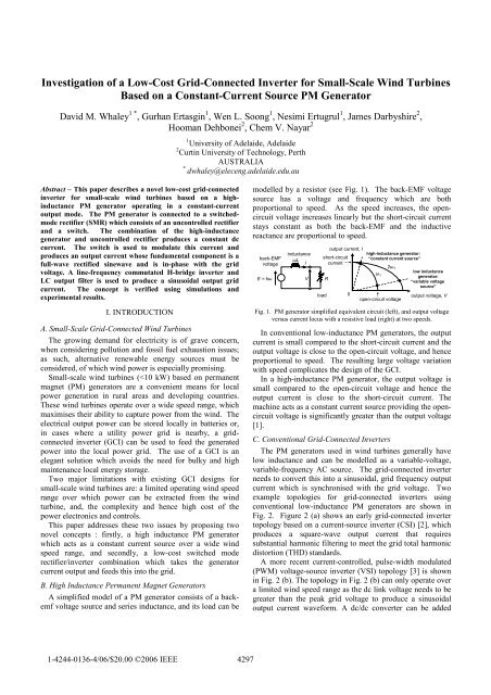
Abstract – This paper describes a novel low-cost grid-connected<br />
inverter <strong>for</strong> small-scale wind turbines based on a highinductance<br />
PM generator operating in a constant-current<br />
output mode. The PM generator is connected to a switchedmode<br />
rectifier (SMR) which consists <strong>of</strong> an uncontrolled rectifier<br />
and a switch. The combination <strong>of</strong> the high-inductance<br />
generator and uncontrolled rectifier produces a constant dc<br />
current. The switch is used to modulate this current and<br />
produces an output current whose fundamental component is a<br />
full-wave rectified sinewave and is in-phase with the grid<br />
voltage. A line-frequency commutated H-bridge inverter and<br />
LC output filter is used to produce a sinusoidal output grid<br />
current. The concept is verified using simulations and<br />
experimental results.<br />
I. INTRODUCTION<br />
1 University <strong>of</strong> Adelaide, Adelaide<br />
2 Curtin University <strong>of</strong> Technology, Perth<br />
AUSTRALIA<br />
* dwhaley@eleceng.adelaide.edu.au<br />
A. <strong>Small</strong>-<strong>Scale</strong> <strong>Grid</strong>-<strong>Connected</strong> Wind Turbines<br />
The growing demand <strong>for</strong> electricity is <strong>of</strong> grave concern,<br />
when considering pollution and fossil fuel exhaustion issues;<br />
as such, alternative renewable energy sources must be<br />
considered, <strong>of</strong> which wind power is especially promising.<br />
<strong>Small</strong>-scale wind turbines (
etween the rectifier and inverter to maintain a constant dc<br />
link voltage, even at lower wind conditions, but this also<br />
adds extra cost and complexity.<br />
Fig. 2. <strong>Grid</strong>-connected inverter topologies with conventional low-inductance<br />
PM generators, showing (a) early grid-connected square-wave CSI,<br />
(b) current-controlled VSI.<br />
D. Proposed <strong>Inverter</strong> Topology<br />
The proposed concept is based on using a high-inductance<br />
PM generator which acts as a current source, with a<br />
switched-mode rectifier (SMR) and inverter (see Fig. 3). A<br />
current source output from the generator is attractive as the<br />
grid-connected inverter output is a controlled current.<br />
Fig. 3. Proposed grid-connected inverter topology, showing circuit diagram<br />
and control block diagram.<br />
The SMR consists <strong>of</strong> an uncontrolled rectifier and a<br />
switch. The combination <strong>of</strong> the uncontrolled rectifier and<br />
high inductance generator acts as a dc constant current source<br />
(see Fig. 1). With the constant current input, the switch acts<br />
as a current chopper (or wave-shaper) in which the output<br />
current is linearly related to the switch duty-cycle.<br />
High-inductance generators have been used in the past<br />
with SMRs to generate a controllable dc output current.<br />
Examples include the use <strong>of</strong> high-inductance wound-field [4]<br />
and interior PM [5] generators <strong>for</strong> automotive applications,<br />
and a surface PM generator [1] <strong>for</strong> a small wind turbine. In<br />
all these cases a dc current output was desired <strong>for</strong> battery<br />
charging purposes and so the duty-cycle <strong>of</strong> the SMR was<br />
kept constant under steady-state conditions.<br />
For this grid-connected inverter application, the duty-cycle<br />
<strong>of</strong> the SMR is modulated to produce an output current which<br />
has the shape <strong>of</strong> a full-wave rectified sinewave and is<br />
synchronised with the grid voltage. This output current is<br />
then fed through a line-frequency commutated inverter (also<br />
known as an “unfolding” circuit) and an LC filter, to produce<br />
the desired sinusoidal output grid current (see Fig. 3).<br />
The proposed topology has similarities to that given in [6],<br />
which describes a three-phase PWM CSI. The main<br />
4298<br />
difference is that a high inductance PM machine is used as<br />
the current source, avoiding the need <strong>for</strong> a bulky dc link<br />
inductor.<br />
A simple control algorithm is proposed based on using the<br />
grid voltage as a reference. The switching <strong>of</strong> the unfolding<br />
circuit and the wave-shaper PWM signal is controlled by the<br />
zero-crossings <strong>of</strong> the grid voltage.<br />
The main advantages <strong>of</strong> the proposed inverter are:<br />
simplified circuit topology and control requirements; the<br />
elimination <strong>of</strong> large, expensive inductors and unreliable dc<br />
link capacitors; and the potential to operate over a wide wind<br />
speed range.<br />
E. Simulation Model<br />
The inverter system was simulated using PSIM ® and the<br />
grid-connected circuit model is shown in Fig. 4. A MOSFET<br />
was used <strong>for</strong> the SMR switch and thyristors <strong>for</strong> the output<br />
inverter H-bridge.<br />
Fig. 4. PSIM inverter circuit model, showing the PM generator, rectifier,<br />
current wave-shaper, H-bridge inverter, voltage-source load, PWM signal<br />
generator, modulation index controller, and zero-crossing detector.<br />
F. Paper Layout<br />
The layout <strong>of</strong> the paper is as follows: section II describes<br />
the experimental test arrangement, and sections III and IV<br />
describe the resistive load and grid-connected results,<br />
respectively.<br />
II. EXPERIMENTAL TEST ARRANGEMENT<br />
This section describes the PM generator, and the power<br />
electronics and controls hardware used to obtain the<br />
experimental results.<br />
A. PM Generator and Dynamometer<br />
An outer-rotor surface PM machine used in Fisher &<br />
Paykel washing machines was selected <strong>for</strong> the test<br />
generator. These have high inductance due to their use <strong>of</strong> a<br />
concentrated stator winding. Its torque rating is consistent<br />
with a several hundred watt wind generator. The generator<br />
used had been rewound to produce an output voltage<br />
compatible with 24 V battery charging. An example <strong>of</strong> a<br />
Fisher & Paykel machine is shown in Fig. 5 (a). The<br />
machine shown is similar but not identical to the test<br />
generator. During the testing, the high-inductance PM<br />
generator was driven by a 5 kW dc machine.<br />
Figure 5 (b) shows the measured and calculated PM<br />
generator’s dc output current versus output voltage<br />
characteristics. This was measured at various speeds when
operating into a resistive load through a three-phase rectifier.<br />
The calculated results were obtained based on the measured<br />
parameters <strong>of</strong> the delta-connected PM generator as shown in<br />
Table 1. These parameters were used in the generator and<br />
rectifier models shown in Fig. 4, and the rectifier was loaded<br />
with a variable resistive load. The calculated results show a<br />
good correspondence with the experimental results and give<br />
confidence in the simulation model. They are also similar to<br />
the idealised characteristics shown previously in Fig. 1.<br />
The generator is a reasonable approximation to a constantcurrent<br />
source when the dc output current is above about 18<br />
A. This corresponds to a peak output voltage limit <strong>of</strong> about<br />
20 V at 600 rpm, and 40 V at 1000 rpm.<br />
DC Current (A)<br />
25<br />
20<br />
15<br />
10<br />
5<br />
1000rpm<br />
800rpm<br />
600rpm<br />
400rpm<br />
200rpm<br />
0<br />
0 25 50 75<br />
DC Voltage (V)<br />
100<br />
(a) (b)<br />
Fig. 5. (a) Photograph, and (b) current-voltage locus <strong>of</strong> PM generator. Solid<br />
lines show simulations, whilst points represent measured experimental data.<br />
TABLE 1<br />
MEASURED PM GENERATOR PROPERTIES<br />
Parameter Value<br />
Stator Connection Delta<br />
Pole Pairs 24<br />
Short-Circuit Line Current 16 Arms<br />
Back-EMF constant, k 0.0668 V/rpm<br />
Phase Inductance, L 2.87 mH<br />
Phase Resistance 0.519 Ω<br />
Maximum Torque 9.08 Nm<br />
B. Power Electronics and Controls Implementation<br />
The SMR was constructed using a line frequency, threephase<br />
uncontrolled rectifier and a high-current MOSFET. As<br />
the generator stator currents are continuous at high speeds,<br />
the rectifier does not need a high-frequency switching<br />
capability. The unfolding circuit was constructed using<br />
thyristors and pulse trans<strong>for</strong>mers were used to drive the<br />
gates. The semiconductor devices are rated at 40A. Sections<br />
<strong>of</strong> the inverter are shown below in Fig. 6.<br />
1<br />
3<br />
2<br />
5<br />
Fig. 6. Sections <strong>of</strong> the inverter hardware, showing the: (1) wave-shaper, (2)<br />
rectifier, (3) thyristor / MOSFET driver circuits, (4) micro-controller, (5)<br />
thyristor H-bridge inverter (unfolding circuit).<br />
4<br />
4299<br />
The inverter was controlled by a micro-controller which<br />
used the zero-crossings <strong>of</strong> the grid voltage to generate the<br />
wave-shaper PWM signal and thyristor trigger pulses. A<br />
PWM switching frequency <strong>of</strong> 4 kHz was used. The PWM<br />
signal was based on a duty-cycle look-up table whose pointer<br />
was reset at positive grid zero-crossings. Adjustment <strong>of</strong> the<br />
modulation index (ma) <strong>of</strong> the PWM wave<strong>for</strong>m allows the<br />
output current magnitude and hence power to be controlled.<br />
III. RESISTIVE LOAD OPERATION<br />
The simulation and experimental testing was conducted in<br />
two parts. In this section, testing <strong>of</strong> the inverter with a<br />
resistive load is described. In the next section, testing with a<br />
voltage source load was then per<strong>for</strong>med.<br />
A. Resistive Load Simulations<br />
Figure 7 shows the simulation results using the model<br />
shown in Fig. 4 <strong>for</strong> the PM generator at 500 rpm <strong>for</strong> an RC<br />
load <strong>of</strong> 0.93 Ω // 2000 µF. The wave<strong>for</strong>ms shown include the<br />
input, wave-shaper output, unfolding circuit output, and the<br />
inverter output currents. These wave<strong>for</strong>ms indicate the<br />
correct operation <strong>of</strong> each inverter stage.<br />
Fig. 7. Calculated inverter currents showing the input, wave-shaper,<br />
unfolded, and output current.<br />
The effect <strong>of</strong> the inverter modulation index (ma) variation<br />
is observed in Fig. 8, where the output current is directly<br />
proportional to ma. With a voltage source load the output<br />
power would be proportional to ma. Figure 8 also shows that<br />
the current THD is increased by reducing ma.<br />
100%<br />
75%<br />
50%<br />
Fig. 8. Calculated inverter output current <strong>for</strong> modulation indices <strong>of</strong> 100%,<br />
75% and 50%.
B. Preliminary Testing<br />
Preliminary tests on the circuit were carried out with two<br />
power sources. Firstly, a dc power supply and series<br />
inductance was used to simulate an ideal constant current<br />
source, and secondly, the PM generator was used.<br />
Figure 9 shows various inverter current wave<strong>for</strong>ms using<br />
both the dc power supply with series inductor (a), and the<br />
PM generator (b), as constant current sources, under the same<br />
test conditions shown in Fig. 7. The wave<strong>for</strong>ms seen are the:<br />
(1) rectifier, (2) wave-shaper, (3) unfolding circuit, and (4)<br />
inverter output currents. The measured results show a good<br />
correspondence to the calculated wave<strong>for</strong>ms <strong>of</strong> Fig. 7, and<br />
give confidence in the simulation model.<br />
(1)<br />
(2)<br />
(3)<br />
(4)<br />
(a) (b)<br />
Fig. 9. Measured current wave<strong>for</strong>ms (a) using a dc power supply and series<br />
inductance, (b) using the PM generator at 500 rpm. <strong>Scale</strong>s are (a) 2 A/div,<br />
and (b) 20 A/div. The zero position <strong>for</strong> each wave<strong>for</strong>m is indicated by the<br />
small arrow on the left.<br />
The wave<strong>for</strong>ms seen in Fig. 7 illustrate the key principles<br />
<strong>of</strong> the inverter, i.e. the power source acts as a current source,<br />
and the wave-shaper acts as a PWM current chopper which<br />
produces a wave<strong>for</strong>m whose fundamental component is a<br />
full-wave rectified sinewave. The action <strong>of</strong> the H-bridge<br />
inverter is also illustrated, and the final output current is<br />
closely sinusoidal.<br />
The PM generator’s rectified output current has a high<br />
frequency ripple component due to the bridge rectifier. It<br />
also shows a lower frequency 100 Hz ripple component due<br />
to the output voltage variation causing an input current<br />
variation (see Fig. 5b). The effect <strong>of</strong> the input current<br />
variations is to cause the amplitude <strong>of</strong> the PWM wave shaper<br />
output to be rather noisy and to cause some distortion <strong>of</strong> the<br />
output current.<br />
Figure 7 also shows that the input current ripple in the PM<br />
generator case does not greatly affect the load current nor the<br />
current THD; see Table II <strong>for</strong> a detailed comparison <strong>of</strong> the<br />
two current source cases.<br />
TABLE II<br />
INVERTER PERFORMANCE FOR EACH CURRENT SOURCE<br />
dc power PM generator PM generator<br />
supply (500 rpm) (1000 rpm)<br />
RMS current input 2.03 A ≈ 21 A ≈ 22 A<br />
Current ripple (input) 0 A 8.8 A 4.4 A<br />
RMS current output 1.26 A 12.8 A 13.8 A<br />
Output power 1.52 W 152 W 178 W<br />
Current THD 3.7 % 4.0 % 3.0 %<br />
4300<br />
C. Constant Input Current Assumption<br />
For high quality grid output current wave<strong>for</strong>ms it is<br />
necessary that the input current be relatively constant at the<br />
peak output voltage. This condition is satisfied when the<br />
peak output voltage is much less than the open-circuit<br />
voltage.<br />
Consider a load resistance <strong>of</strong> 1 Ω. With ma = 100%, Fig.<br />
10 indicates a peak current <strong>of</strong> about 17 A at low output<br />
voltages. The peak output voltage is thus about 17 V. The<br />
voltage-current loci indicate that changing the PM generator<br />
speed from 500 rpm to 1000 rpm, increases the open-circuit<br />
voltage from 45 V to 90 V, but has little effect on the shortcircuit<br />
current.<br />
DC Current (A)<br />
25<br />
20<br />
15<br />
10<br />
5<br />
R L =1Ω<br />
R L =5Ω<br />
1000rpm<br />
0<br />
0 20 40<br />
500rpm<br />
60 80 100<br />
DC Output Voltage (V)<br />
Fig. 10. Simulated IV locus <strong>of</strong> generator <strong>for</strong> speeds <strong>of</strong> 500 and 1000 rpm<br />
(from Fig. 5b) including output load lines <strong>for</strong> two values <strong>of</strong> load resistance.<br />
Figure 11 illustrates the measured input and output<br />
currents <strong>for</strong> these two speeds. Increasing the speed clearly<br />
makes the input current more constant. Note that the peak<br />
input current does not change much, but the ripple is<br />
reduced. This slightly increases the average input current<br />
and hence the output current. The higher speed also<br />
significantly improves the output current THD, from 4% to<br />
3% (see Table II).<br />
scale: 10A/div scale: 10A/div<br />
(a) (b)<br />
Fig. 11. Measured inverter input (top) and filtered output (bottom) currents,<br />
<strong>for</strong> generator speeds <strong>of</strong> (a) 500 rpm, and (b) 1000 rpm. <strong>Scale</strong>s are 10A/div.<br />
Consider an example where the constant current<br />
assumption breaks down. Let us increase the load resistance<br />
by a factor <strong>of</strong> five to 5 Ω (see Fig. 10). With an ideal<br />
constant current source input, the peak output voltage should<br />
increase by a factor <strong>of</strong> five to about 85 V. However at 500<br />
rpm the open-circuit voltage is only 45 V and so the constant<br />
current input assumption will break down. This case is<br />
illustrated in Fig. 12 showing both simulated and measured<br />
results <strong>for</strong> the input and output current wave<strong>for</strong>ms <strong>for</strong> a load<br />
resistance <strong>of</strong> 5 Ω, which show a good correspondence. Note<br />
the filter capacitor was reduced by a factor <strong>of</strong> 5 to maintain<br />
the same filter time-constant.
scale: 10A/div<br />
(a) (b)<br />
Fig. 12. <strong>Inverter</strong> input (top) and output (bottom) current <strong>for</strong> RL = 5 Ω // Cf =<br />
100 µF. (a) shows the simulation and (b) shows the measured results.<br />
IV. EXPERIMENTAL GRID-CONNECTED TESTING<br />
In this section the grid-connected operation <strong>of</strong> the inverter<br />
was tested. Due to the low voltage generator used, this was<br />
experimentally simulated by using an autotrans<strong>for</strong>mer to<br />
provide a reduced-voltage ac voltage source load. The<br />
autotrans<strong>for</strong>mer’s leakage reactance also conveniently<br />
provided some inductance to filter the output current (see<br />
Fig. 3).<br />
The grid-connection was per<strong>for</strong>med in two stages. The<br />
inverter was initially operated into a resistive load. The<br />
magnitude <strong>of</strong> the output voltage <strong>of</strong> the inverter and<br />
autotrans<strong>for</strong>mer were made equal and it was verified that the<br />
two voltages had the same phase. The intermediate gridconnection<br />
stage involved connecting the autotrans<strong>for</strong>mer in<br />
parallel with the resistive load. In this case, ideally the<br />
autotrans<strong>for</strong>mer should provide zero current and the output<br />
power <strong>of</strong> the inverter should still be absorbed by the load<br />
resistance. The pure grid-connection stage involved<br />
removing the load resistor and hence feeding the inverter<br />
output power into the grid.<br />
A. Preliminary <strong>Grid</strong>-<strong>Connected</strong> <strong>Inverter</strong> Results<br />
Figure 13 (a) shows the inverter, grid and resistive load<br />
currents <strong>for</strong> the intermediate grid-connected stage. The<br />
resistive load current wave<strong>for</strong>m is a scaled version <strong>of</strong> the<br />
sinusoidal grid voltage wave<strong>for</strong>m shown in Fig. 13 (b).<br />
Ideally the grid current should be zero in this situation,<br />
however in practice it supplies the difference between the<br />
slightly distorted inverter output current wave<strong>for</strong>m and the<br />
resistive load current wave<strong>for</strong>m.<br />
(a) (b)<br />
Fig. 13. Intermediate grid-connected case measurements, (a) shows the<br />
inverter and grid currents (top) and the resistive load current (bottom), and<br />
(b) shows the grid voltage. <strong>Scale</strong>s are (a) 10A/div, (b) 5V/div.<br />
The pure grid-connected case was obtained by removing<br />
the load resistance. The resulting grid voltage and current<br />
4301<br />
wave<strong>for</strong>ms are given in Fig. 14. Removing the load<br />
resistance causes the inverter current to flow through the<br />
autotrans<strong>for</strong>mer’s leakage inductance into the mains. The<br />
extra inductance causes the inverter current to lag the voltage<br />
by about 27° (power-factor ~ 0.89). This can be corrected by<br />
appropriately adjusting the control timing. The current<br />
wave<strong>for</strong>m also shows greater harmonic distortion. This<br />
could be partly related to resonance between the filter<br />
capacitance and the trans<strong>for</strong>mer leakage reactance.<br />
voltage current<br />
Fig. 14. Measured inverter output voltage and current <strong>for</strong> the pure gridconnected<br />
case. <strong>Scale</strong>s are 10V/div (voltage), and 5A/div (current).<br />
The effect <strong>of</strong> varying the filter capacitance, grid voltage<br />
and modulation index are studied in the following sections.<br />
B. Effect <strong>of</strong> <strong>Grid</strong> Voltage Variation<br />
The inverter current was monitored <strong>for</strong> rms grid voltages<br />
<strong>of</strong> 11, 13, and 15 V, see Fig. 15. It is seen that increasing the<br />
grid voltage causes the output current to decrease in<br />
magnitude and the THD to increase. This is because the<br />
generator is shifted toward the voltage source region and its<br />
output current shows increasing ripple. The grid voltage<br />
(secondary <strong>of</strong> autotrans<strong>for</strong>mer) THD may be related to the<br />
current THD due to the trans<strong>for</strong>mer leakage reactance.<br />
Fig. 15. <strong>Inverter</strong> output currents (left) and grid voltages (right) <strong>for</strong> the purely<br />
grid-connected case, showing the effect <strong>of</strong> increasing the grid voltage. The<br />
grid rms voltages are 11 V (top), 13 V (middle) and 15 V (bottom). <strong>Scale</strong>s<br />
are 10A/div.<br />
Figure 16 shows the inverter current THD as the grid<br />
voltage is increased. This experiment was first per<strong>for</strong>med<br />
whilst maintaining a constant filter capacitance (Fig. 16a),<br />
and was repeated whilst adjusting the filter capacitance (Fig.<br />
16b) to obtain the lowest THD <strong>for</strong> each grid voltage. The<br />
large current THDs occur in the constant capacitance case, as<br />
the filter inductance is increased by increasing the grid<br />
voltage (increasing turns ratio). Hence the filter capacitance<br />
was varied during the repeated tests, to reduce the THD.
THD (%)<br />
25<br />
20<br />
15<br />
10<br />
5<br />
Current<br />
0<br />
0 5 10 15<br />
Volatge<br />
20 25<br />
<strong>Grid</strong> Voltage (V)<br />
THD (%)<br />
25<br />
20<br />
15<br />
10<br />
5<br />
Current<br />
Voltage<br />
0<br />
0 5 10 15 20 25<br />
<strong>Grid</strong> Voltage (V)<br />
Fig 16. <strong>Inverter</strong> current and voltage THD vs. grid voltage, <strong>for</strong> (a) constant<br />
filter capacitance (600 µF), and (b) various capacitances (300-2000 µF) to<br />
minimise current THD.<br />
C. Effect <strong>of</strong> Modulation Index Variation<br />
The PWM modulation index was varied <strong>for</strong> the pure gridconnected<br />
case, and the effect on the inverter current is seen<br />
below in Fig. 17. The filter capacitance and grid voltage were<br />
kept constant, and hence the output power should be linearly<br />
proportional to ma.<br />
Fig. 17. Measured inverter output current <strong>for</strong> modulation indices <strong>of</strong> 100%<br />
(top), 80% (middle) and 60% (bottom) <strong>for</strong> the pure grid-connected case.<br />
The effect <strong>of</strong> the modulation index variation is seen in Fig.<br />
18. Figure 18 (a) shows the current and voltage magnitude<br />
response to the ma variation, whereas Fig. 18 (b) shows the<br />
resulting current and voltage THD.<br />
For an ideal constant current source, the inverter current is<br />
expected to vary linearly with the ma; however Fig 18(a)<br />
shows that the measured inverter output current is slightly<br />
larger than expected, and that the grid voltage decreases<br />
slightly with decreasing inverter current. The increased<br />
current at low values <strong>of</strong> ma is caused by the PM generator<br />
output current increasing slightly with reduced loading. The<br />
inverter voltage reduction is likely related to the regulation <strong>of</strong><br />
the auto-trans<strong>for</strong>mer.<br />
Current & Voltage (PU)<br />
1<br />
0.8<br />
0.6<br />
0.4<br />
0.2<br />
Voltage<br />
scale: 10A/div<br />
Current<br />
0<br />
0 20 40 60 80 100<br />
Modulation Index (%)<br />
THD (%)<br />
15<br />
10<br />
5<br />
Current<br />
Voltage<br />
0<br />
0 20 40 60 80 100<br />
Modulation Index (%)<br />
Fig. 18. (a) measured and expected inverter current and grid voltage<br />
magnitudes (normalised to values at 100% modulation index), and (b)<br />
measured current and voltage THD, vs modulation index.<br />
4302<br />
VI. CONCLUSIONS<br />
This paper proposed a novel grid-connected inverter <strong>for</strong> a<br />
small-scale wind turbine based on a high inductance PM<br />
generator combined with a switched-mode rectifier (SMR)<br />
and line-frequency commutated H-bridge inverter stage. The<br />
key results are:<br />
• the high-inductance PM generator must be designed to<br />
have a rated output voltage which is much smaller than<br />
its open-circuit voltage at maximum speed, in order <strong>for</strong> it<br />
to act as a constant current source;<br />
• the control <strong>of</strong> the SMR is straight<strong>for</strong>ward as its output<br />
current is linearly related to duty-cycle;<br />
• it was experimentally demonstrated that a controllable<br />
magnitude ac sinusoidal output current could be<br />
obtained when operating into both a resistive and voltage<br />
source load (simulating grid-connected operation);<br />
• simulations and experimental testing was used to<br />
examine the effect <strong>of</strong> varying the filter capacitance and<br />
output power on the inverter current THD.<br />
In future, it is planned to use a higher voltage PM<br />
generator to demonstrate rated voltage grid-connected<br />
inverter operation, to integrate a maximum power point<br />
tracker in the controller, and to per<strong>for</strong>m field testing on a<br />
small-scale wind turbine. During this study, the control and<br />
LC filter time-constant will be optimised, to minimise the<br />
THD, and maximise efficiency over the expected turbine<br />
operating range.<br />
ACKNOWLEDGMENT<br />
This work was supported by an Australian Research<br />
Council Discovery grant, DP0342874. The technical support<br />
from the Electrical and Electronic Engineering workshop<br />
staff in the construction <strong>of</strong> the test rigs and machine set-up is<br />
gratefully acknowledged.<br />
REFERENCES<br />
[1] D.M. Whaley, W.L. Soong and N. Ertugrul, “<strong>Investigation</strong> <strong>of</strong><br />
switched-mode rectifier <strong>for</strong> control <strong>of</strong> small-scale wind turbines”,<br />
Proceedings <strong>of</strong> IEEE Industry Applications Society Annual Meeting,<br />
2005, Vol. 4, pp. 2849-2856.<br />
[2] Z. Chen and E. Spooner, “Wind turbine power converters: a<br />
comparative study”, Proceedings <strong>of</strong> the IEE Power Electronics and<br />
Variable Speed Drives, (IEE Conf. Publ. No. 456), Sept. 1998, pp.<br />
471-476.<br />
[3] H. Huang and L. Chang, "Energy-flow direction control <strong>of</strong> gridconnected<br />
IGBT inverters <strong>for</strong> wind energy extraction," presented at<br />
Electrical and Computer Engineering, 2000 Canadian Conference on,<br />
2000.<br />
[4] D.J. Perreault and V. Caliskan, “Automotive Power Generation and<br />
Control”, IEEE Transactions on Power Electronics, Vol. 19, Issue 3,<br />
May 2004, pp. 618-630.<br />
[5] C.Z. Liaw, D.M. Whaley, W.L. Soong, and N. Ertugrul, “<strong>Investigation</strong><br />
<strong>of</strong> <strong>Inverter</strong>less Control <strong>of</strong> Interior Permanent-Magnet Alternators”,<br />
IEEE Transactions on Industry Applications, Vol. 42, Issue 2, March-<br />
April, 2006, pp. 536-544.<br />
[6] A. Bendre, I. Wallace, J. Nord and G. Venkataramanan, “A current<br />
source PWM inverter with actively commutated SCRs”, IEEE<br />
Transactions on Power Electronics, Vol. 17, Issue 4, July 2002, pp.<br />
461-468.<br />
[7] T. Wildi, “Electrical Machines, Drives, and Power Systems”, 5th ed.,<br />
Upper Saddle River: Prentice Hall, 2002.