CM 1700-2200-2400 2006
CM 1700-2200-2400 2006
CM 1700-2200-2400 2006
- No tags were found...
Create successful ePaper yourself
Turn your PDF publications into a flip-book with our unique Google optimized e-Paper software.
CONTENTSDeclaration of conformity ..................................................................... 2General description ......................................................................... 3Preface ................................................................................... 3Technical specifications ...................................................................... 4Safety suggestions for mounted mowers ......................................................... 5Danger sticker explanation texts ................................................................ 7Mounting instructions ......................................................................... 8Tractor provisions........................................................................... 10Hitching to the tractor ........................................................................ 11Height limiting chain ......................................................................... 11Hydraulic connection ........................................................................ 11Coupling shaft connection .................................................................... 12Shortening procedure of the coupling shaft ....................................................... 12Operating and transport position ............................................................... 13Mowing height ............................................................................. 14The swath board ............................................................................ 14Horizontal lifting kit .......................................................................... 15Obstacle protection ......................................................................... 16Protection canvas........................................................................... 16Mowing ................................................................................... 17Slope mowing .............................................................................. 17MAINTENANCEExchanging blades .......................................................................... 18Tensioning V-belts .......................................................................... 29Oil inspection .............................................................................. 20Plugs and oil contents ....................................................................... 20Adding and changing oil ...................................................................... 21Inspection of bolts and nuts ................................................................... 22Timing the mowing discs ..................................................................... 22Lubrication chart ............................................................................ 22Accessories ............................................................................... 23Torques .................................................................................. 24Trouble shooting table ....................................................................... 251
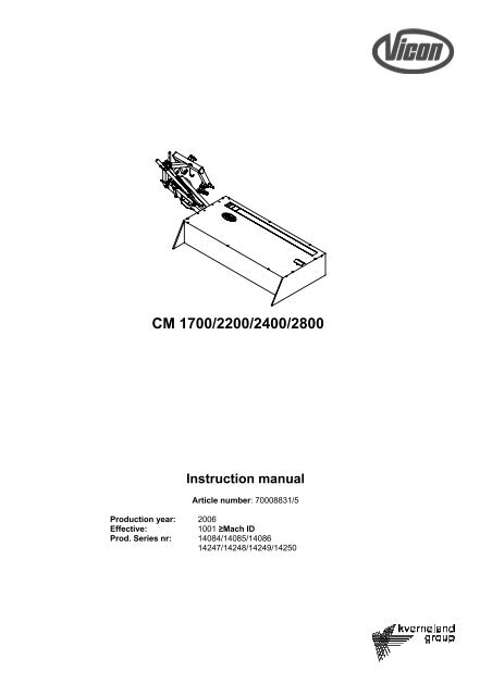
TECHNICAL SPECIFICATIONSTYPE <strong>CM</strong> <strong>1700</strong> <strong>CM</strong> <strong>2200</strong> <strong>CM</strong> <strong>2400</strong> <strong>CM</strong>2800Working width 1,65 m 2,15 m 2,40 m 2,80 m5’4” 7’1” 7’10” 9’2”Transportwidth from the 1,20 m 1,20 m 1,20 m 1,30 mmiddle of the tractor 3’11” 3’11” 3’11” 4’3”Weight (PTO-shaft included) 390 kg 455 kg 495 kg 580 kgImp. lbs. 600 lbs. 738 lbs. 804 lbs. 942 lbs.US lbs. 860 lbs. 1003 lbs. 1091 lbs. 1279 lbs.Required horsepower 26 kW(36 HP) 30 kW(42 HP) 33 kW(46 HP) 41 kW (55 HP)PTO-speed 540 rpm 540 rpm 540 rpm 540 rpmType of linkage pins CAT. I + II CAT. II CAT. II CAT. IINumber of discs 4 6 6 8Number of blades 12 18 18 24Blade length 120 mm 107 mm 120 mm 107 mm4 23/32 ” 4 7/32 ” 4 23/32 ” 4 7/32 ”Disc rpm 2850 rpm 2850 rpm 2850 rpm 2850 rpmBlade cutting speed 2½ ft/sec 2½ ft/sec 2½ ft/sec 2½ ft/secV-belts 3 4 4 4Cutter bar angle vertical 90° 90° 90° 90°slope 45° 45° 45° 45°* Type B, spec. 2360OIL CONTENTLubrication* SAE 80W-90 SAE 80W-90 SAE 80W-90 SAE 80W-90Content gear box 0,25 l 0,25 l 0,25 l 0,25 l(in U.S. Quarts) 0.25 0.25 0.25 0.25Content cutter bar 1,50 l 1,75 l 1,75 l 2,15 l(in U.S. Quarts) 1.5 1.75 1.75 1.75Operating temp. max 70° C 70° C 70° C 70° C158° F 158° F 158° F 158° F* Oil specification: MIL-L-2105 C API-GL 5 (SAE 80W-90)4
SAFETY REGULATIONGSDANGER:If you should come across this symbol and heading, there is a direct hazardto life and health of man and animal.ATTENTION:NOTE:This heading refers to possible risks of damage to machine(s), crops, buildings, etc., but also topossible financial and/or legal problems (warranty, liability, and the like).This indicates a tip to make the work easier, better and safer.Read the operating instructions before using the machine and follow the instructions.GeneralNOTE:Pass on all safety advice, etc. to other (fellow) users!SAFETY SUGGESTIONS FOR MOUNTED MOWERS1. Tractors with mounted machines may only be driven by persons aged 18 or older. Young people of 16 and 17must be in possession of a tractor driving licence.2. Starting and test runs may never take place in an enclosed space because of the risks of inhaling exhaustfumes.3. Inspect the machine and the tractor on traffic and operational safety prior to any use!4. In addition to the specific directions of this instruction manual pay attention to the general regulations withregard to safety and the prevention of accidents!Keep the machine clean, which includes free from any mowed crop and in this way prevent the risks of fire!5. The stickers attached on or to the machine contain important directions for safe use; following the instructionsserves your own safety!6. Adhere to the regulations of the Highway Code when using a public road!7. Make sure to be familiar with all systems and control devices and their functions prior to working with them! Itwill be too late for that when you are working!8. When using the machine always wear close-fitting clothes! Avoid any loose (articles of) clothing!9. After switching off the drive the machine will need time to slow down! Do not approach the cutter bar beforethe machine has come to a full standstill (see also item 47)!10. Look around the machine (and the tractor) before driving off and before switching on the machine! Look out forchildren! Make sure you have sufficient visibility.11. It is prohibited to be on the machine during work and transport!12. Connect accessories as prescribed and exclusively mount appliances to the appropriate provisions and makesure of a correct locking.13. Be especially careful when connecting and disconnecting the machine and the tractor respectively! Make surethe parking support is in the correct position when the mower is hitched and unhitched.14. Adhere to the maximum permissible transport dimensions!15. Inspect and mount any transport accessories, e.g. lighting, warning devices and the like and any protectiveparts!16. Prior to transporting the machine on a public road, put it in the prescribed position and lock this according toregulations.17. When driving the driver's seat must be occupied at all times!18. Always adjust the driving speed to the conditions of the environment and the terrain! When driving up anddown hills and when driving across a slope do not make any sudden turns!19. Mounted machines influence the handling, manoeuvrability and braking performance! So make sure ofsufficient steering and braking, if necessary by using front weights!20. When taking turns pay attention to the extended width/length (turning circle) and/or large mass (sluggishness)of the machine!21. Only work with machines when their protection is complete and intact and is placed in its functional position!The protection of the mower prevents access to danger zones. Therefore keep it in a proper condition. It ismeant for your safety and that of others!22. No one may be within the working and danger zone of the mower! Keep sufficient distance to the -invisiblebladesof a running machine!23. Do not enter the turning circle of the mower!5
24. Fully lower the machine prior to leaving the tractor! Switch off the engine and remove the ignition key!25. No one may be between the mower and the tractor unless the vehicle has been protected against rolling awayby means of the parking brake or chocks.26. When mounting a machine in the three-point linkage, put the controls of the power lift in a position in whichinadvertently lifting or lowering is not possible.27. The linkage category of the mower must always correspond with that of the tractor; adapt the mower ifnecessary!28. There is a danger of accidents by crushing or jackknifing inherent to using the three-point linkage.29. The controls for the three-point linkage outside the tractor cab must be operated without standing between thetractor and the mower.30. Always make sure of sufficient lateral fixation of a machine in transport position.31. When driving on public roads with a lifted machine, the operating handle of the three-point linkage must beprotected against lowering.32. Check the condition of blades and blade bolts prior to mowing.33. DANGER: Intensive use without hearing protection may cause hearing loss!34. Switch off the PTO shaft, switch off the engine and remove the ignition key prior to working on the machine.DANGER: The machine needs time to slow down! Wait until it has stopped completely (seealso item 47).35. Immediately repair any damage, prior to working with the machine again!Drive through pto and coupling shaft36. Prior to use, inspect the coupling shaft for any defects or wear.37. Only use the power take-off shaft prescribed by the manufacturer!38. Protection sleeves and covers of the pto guard must be mounted and in good condition!39. Ensure the prescribed overlap of the coupling shaft halves and protection sleeves, both in transport and inoperating position.40. Only mount and dismount the coupling shaft when the tractor engine is stopped and the ignition key isremoved.41. Always ensure that the coupling shaft is mounted and protected correctly.42. Lock the coupling shaft protection to prevent it from rotating by mounting the chain(s) to a fixed point.43. Ensure that the rotating direction of the pto matches the machine to be driven before engaging the pto! Thepto speed must never exceed 540 rpm.44. Never engage the pto when the engine is stopped!45. When the pto is running, there must be no one within the reach of the rotating pto or coupling shaft!46. Always disengage the pto when there is a risk that the angle of the universal joint becomes to great, but alsowhen it is not needed!47. DANGER: After disengaging the pto there is a danger resulting from the slowing down ofthe machine because of mass inertia! The mowing discs rotate at a high speed and areall but invisible: so stay clear of the mower! Only start working on it when all parts havestopped!48. Machines that are driven by means of a coupling shaft, as well as the coupling shaft itself, must only becleaned, lubricated or adjusted after switching off the pto and the engine and removing the ignition key!49. Put a removed coupling shaft in the available holder on or in the machine!50. Slide the protection sleeve over the pto as soon as the coupling shaft has been removed!6
DANGER STICKER EXPLANATION TEXTS1. Stop the engine and prevent any starting up againwhen working on the machine.In this way you will prevent the perilous situations arisingwhen a machine suddenly starts running. Also think ofaccidental engaging if the engine should remain running!2. Keep clear: objects may be flung away!Also when the machine is used correctly, stones and the likemay be flung away. Therefore always remain clear of thedanger zone. Be particularly careful when working in thevicinity of roads and buildings! After disengaging the machineit will take some time to slow down: wait until it has reached acomplete standstill!3. When hitching the machine to the tractor, onlyoperate the three-point linkage from outside thedanger zone!In between the tractor and the machine you are in danger ofbeing crushed between the three-point linkage. Thereforeonly operate the three-point linkage from outside the dangerzone when hitching the machine to the tractor!4. Stay clear of V-beltsAlways keep sufficient distance from running V-belts!5. Do not approach the machine until it has come to acomplete standstill!A rotating machine will never come to a direct standstill: it willcontinue running for a while. As long as a machine is runningits rotating parts are hard to see or invisible. Caution, not onlyblades are a threat to life. Keep your distance until everythinghas come to a full standstill!6. Stay clear of folding parts of a machine!Such a part can suddenly come down with great force(because of weight, but also because of hydraulic power!). Aswitched-off engine in itself does not prevent all accidents:the hydraulic system may still be under pressure and youcannot switch off gravity!7. Keep clear of a coupling shaft!Clothing, hands, hair etc. can be caught in the moving partsand dragged around them with all its consequences! Makesure of a correct protection of the coupling shaft(s). Payspecial attention to coupling shafts behind plates, without aprotection of their own.8. Keep clear: objects may be flung away!Also when the machine is used correctly, stones and the likemay be flung away. Therefore always remain clear of thedanger zone. Be particularly careful when working in thevicinity of roads and buildings! Therefore replace the canvaswhen it is worn. This canvas is specially designed to protectyou from flying objects.7
MOUNTING INSTRUCTIONSThe Vicon disc mowers are packed compactly and preassembledin units. Assemble the various units on a level,clean floor. For reasons of safety this should always be doneby two persons working together and using a forklift.S Open the crate and arrange the various units convenientlyon the floor.S Loosen M16 bolt (1) and flip up the the lever.S Unfold the frame (1).S Tighten M16 bolt (1). (210 Nm / 154 ft.lbs)S Mount the attachment (2) and the telescopic spring (3).S Put the break-away safety (5/8) through the hole of theprotection cover (14) until the spring is against the cover.<strong>CM</strong> <strong>1700</strong>/<strong>2200</strong>/<strong>2400</strong>S Mount the break-away safety with pin (15) to the frame (16)with the spring pointing outward (5).<strong>CM</strong> 2800S Mount the break-away safety with the fork side (8) to theframe and the break-away latch pointing outward.S Mount the protective cover (14) to the frame (16) using thesupplied washers and cap nuts.S Mount the hitch frame (4).<strong>CM</strong> <strong>1700</strong>/<strong>2200</strong>/<strong>2400</strong>S Mount the break-away safety (5) to hitch frame (4)simultaneously with bush (6) and pin (17) as indicated onthe drawing.<strong>CM</strong> 2800S Mount the break-away safety (8) with the eye to the hitchframe (4).S Mount the lift cylinder (7).S Mount the canvas frame holder (13).ATTENTION:Bush (6) has to be fitted according to thedrawing to ensure a correct functioning of thebreak-away device.Only for model <strong>2200</strong>, <strong>2400</strong> and 2800:S Mount the rubber strip between the canvas frame holder(13) and the filler piece (12).Consult the parts book for mounting the various components.In some cases it lists the specific torques. If not, we refer tothe table on page 24.8
S Mount the corner plate (21) with the stop for the swathboard to the cutter bar.S Mount the swath board (22) and the swath stick (23).S Mount the canvas frames (18) with the height adjustment(19) in the bottom hole.S Fit guard (20) with the descending side in the direction oftravel.S Next install the canvas (24).S Check all bolt connections.S Remove the tape from the bleeder plug of the gearbox(25).S Check the oil levels of gearbox and cutterbar.ATTENTION:Make sure that the tape around thebreather plug (25) is removed to preventoverheating of the gearbox.9
TRACTOR PROVISIONSThe tractor must be equipped with a three-point linkage withCat. I or Cat II balls. A correct functioning of the top link andthe crank of the draft link adjustment (4) is important.The standard tractor track width is 1.50 metres/5’ (fig. 2). Fordifferent track widths you can adjust the lift pins (Cat. II).The <strong>CM</strong> <strong>1700</strong> is equipped with Cat. I linkage pins (1). Fillerbush (2) makes the mower also suitable for Cat. II.Track width left right<strong>CM</strong><strong>1700</strong> (Cat. I)130-150cm(fig.1) Short pin* Cat. I Long pin* Cat. I<strong>CM</strong> <strong>2200</strong>/<strong>2400</strong> (Cat. II)150 cm (fig. 2) Short pin inside Long pin outside160 cm (fig. 3) Short pin outside Long pin centre170 cm (fig. 4) Long pin outside Short pin inside* Linkage pin mounted on the inside of the hitch frame.Cat. I linkage pins optionally available for <strong>CM</strong> <strong>2200</strong> and <strong>2400</strong>.<strong>CM</strong> 2800 (Cat. II)Refer to the table below and figures 7, 8 and 9 on page 11.Track width left right160 cm (fig. 7) Short pin inside Long pin outside170 cm (fig. 8) Short pin outside Long pin centre180 cm (fig. 9) Long pin outside Short pin insideOperating the lift cylinderTo tractor has to be equipped with one single acting valve (6)with flotation position to operate the cilinder.The tractor should be equipped with a system (3) that limitesany lateral movement of the mower and allows the operator toset the machine in the right position behind the tractor.NOTE:The three-point linkage of the tractor mustfunction accurately and must be lubricated wellfor correct mower adjustment.10
HITCHINGNote Precise hitching of the mower is highly important toobtain a good mowing result. The tractor power lift mustoperate accurately and be well-oiled to be able toproperly adjust the mower.SSSPut the lower links of the tractor at the same height as themower linkage pins (1). Use the lift rod adjustment (4) tocompensate any height difference.Mount the check chain to the linkage pin.First mount the mower to the lower links before mountingit to the top link. Do not forget to correctly place retainingclips or retaining pins.S Lift the mower to operating height and slide the parkingsupport up into transport position (2).The correct operating height as measured between thelinkage pins and the ground is for:<strong>CM</strong> <strong>1700</strong>-<strong>2400</strong> = 40 cm (16') ; <strong>CM</strong> 2800 = 45 cm (17'7")SNow use the lift rod adjustment (4) to put the lower links ofthe tractor at the same height. In operating and transportposition the hitch frame must be horizontally behind thetractor.When the mower is at the correct height, the chain betweenthe mower linkage pin and the tractor can be mounted.HYDRAULIC CONNECTIONConnect the hydraulic lift cylinder to the tractor valve (singleactingvalve) (6). The hose connector on the cylinder containsa 1 mm throttle plate (for <strong>CM</strong> 2800 1.5 mm) to restrict the oilflow.NEVER remove this throttle plate!This provision ensures that the mower cannotsuddenly drop down with possible considerablematerial damage and bodily injury as aconsequence.ATTENTION:Before you start mowing check thehydraulic connections and hoses fordamage and leakage.DANGER: Always first switch off thetractor engine prior to solvingany malfunctions.S Adjust the lateral checking device (3) in such a mannerthat no linkage arm movement is possible.11
COUPLING SHAFT CONNECTIONSHORTENING PROCEDURE COUPLING SHAFTSSSPlace the drive shaft of the mower on the same level asthe tractor PTO-shaft (8).Place both coupling shaft sections and hold them side byside (9).Now check the length; the tubes must overlap as much aspossible, with a minimum of 150 mm/6”. However, theprofile tubes must have a minimum clearance of 25 mm/1”at the ends (10).If the coupling shaft needs shortening, please refer to theinstructions from your coupling shaft supplier for the correctprocedure.ATTENTION: The maximum coupling shaft angle is 30degrees (11). ALWAYS first switch off thePTO-shaft when raising or lowering themower to its maximum position.12
OPERATING POSITIONS Use the hydraulic cylinder (1) to lower the cutter bar tooperating position.S Put the lever of the hydraulics into the ‘float’ position.S Put the linkage pins at a height of:- 40 cm <strong>CM</strong><strong>1700</strong>-<strong>2400</strong>- 45 cm <strong>CM</strong>2800above the groundS Make sure the headstock is fitted horizontal behind thetractor.S Finally turn the top rod (if necessary) until the protectivecanvas is parallel to the ground (2).Only for <strong>CM</strong> <strong>2400</strong>:For tractors without floating position (pressure-free return) youmust hold the lever for a few seconds after the mowertouches the ground. Then the spring head on the cylinder willsend a sufficient quantity of oil back to the tractor to let themower follow the ground closely. Pin (9) should be in themiddle of the slot hole when the machine is attached correctlyto the tractor.Transport position:S Use the power lift to lift the machine off the ground untilthere is a clearance of at least 10 cm/4” under the innerskid (3).S Pull the rope of the horizontal lifting kit and place thecutter bar in a vertical position (4) by means of thehydraulic cylinder.<strong>CM</strong> <strong>1700</strong>/<strong>2200</strong>/<strong>2400</strong>S Mount the cylinder locking device (5) and lock it with thelocking spring (6).<strong>CM</strong> 2800The transport position can be additionally secured by closingthe valve on the cylinder.TO DISMOUNT AND STORE THE MOWER:S Slide the stand down (7).S Fully lower the machine in working position (1).S Unhitch the mower en store the pto shaft in the holder (8).NOTE:Always store the mower in operating position.13
HORIZONTAL LIFTING KITThe mower is equipped with a lifting kit enabling the driver tolift the mower quickly at the head ends.Attach the rope (2) to the back of the tractor or the cabin to beable to put the machine in work or transport position from thedrivers seat.ATTENTION: To ensure correct operation of the latch (1)ensure the rope is routed correctly (3)Transport position:By pulling the rope (2) in your cabin, you disengage the latch(1). By using the hydraulic cylinder the mower can be placedin vertical transport position (4)..<strong>CM</strong> 2800The transport position can be additionally secured by closingthe valve on the cylinder.Working position:When latch (1) is in its down position, the mower will lifthorizontally with the hydraulic cylinder, without using the lowerlinkage arms. Latch (1) is in working position until the rope (2)is pulled.15
OBSTACLE PROTECTIONThe special breakaway safety (1) on the main frame ensuresthat the cutter bar can swing back as soon as it hits anobstacle. If this happens, you should stop the tractor ATONCE.When you have removed the obstacle, you can reset thebreakaway safety by reversing the tractor a little.PROTECTIVE CANVASThe canvas frame (3) can be set in two positions (4). Notethat in no event the canvas must be put higher than thefactory settings allow.Putting the canvas frame (3) in a higher position may improvethe cutting quality when mowing under hilly conditions.NOTE:Ensure that the protection is always operatingcorrectly and adjust the spring length (2) at 145 mm/5 11/16 ’‘ (<strong>CM</strong> <strong>1700</strong>/<strong>2200</strong>/<strong>2400</strong>) or (5) 2x 82 mm/3,23"(<strong>CM</strong> 2800).16
MOWINGThe PTO-speed must be 540 revolutions/min (3), the drivingspeed (4) between 7 and 12 km/hr (4½ - 7½ mph).NOTE:Mow at a lower speed along the edge of the field,because of possible obstacles or ditches. Bear inmind that the manoeuvrability of the tractor isreduced when the cutter bar hits an obstacle or landsin the ditch.SLOPE MOWING:SSUse the cylinder to carefully lower the mower at the edgeof the ditch until the mower is on the slope (1).The maximum permissible mower angle is 45/ for the <strong>CM</strong><strong>1700</strong>-<strong>2400</strong> and 35/ for the <strong>CM</strong> 2800.<strong>CM</strong> <strong>2400</strong> and 2800:SLower the cutter bar to operating position with the liftcylinder, until the pin is approximately in the centre of theslotted hole (2).If the mowing result should leave anything to be desired, referto the trouble shooting table at the back of this manual.DANGER:DANGER:Always first switch off the tractorengine prior to solving anymalfunctions.Never let the mower run in verticalposition, as it is not protected inthat condition.17
MAINTENANCEEXCHANGING BLADESThe blades have two cutting edges and so are reversible.When reversing blunt blades, always remount them on thesame mowing disc. If you don't, unbalance may causevibration which results in excessive wear. There are bladesrotating clockwise and those rotating anti-clockwise; thedirection of rotation is indicated with an arrow (1). The bladebolts can be slackened with a supplied spanner. For mountingand dismounting the blades, the cutter bar must be inoperating position.S Put a piece of wood or a similar object between themowing discs to prevent disc rotation (2).S First clean the space around the nut and, after taking outthe bolt, also clean its fit. (3).NOTE:When remounting the cutter discs, you should timethem as shown in fig. 1.The <strong>CM</strong> <strong>2200</strong> and 2800 are equipped with 107 mm/4 7/32 ”blades. The <strong>CM</strong> <strong>1700</strong> and <strong>2400</strong> are equipped with blades of alength of 120 mm/4 23/32 ” (4).SSWhen placing new blades check that they have the correctlength. Blades which are too long may cause bearingdamage to the <strong>CM</strong> <strong>2200</strong>.Regularly check the torques of bolts and nuts as listed onpage 24.NOTE:Use genuine Vicon blades, they do have a longerservice life! Regularly replace the blade bolts;always use new bolts and nuts with every secondset of blades.DANGER:Regularly check the condition of bladesand blade bolts. Excessive play (5)between blade bolt and the hole(max. 5 mm / 3/16") in the blademay cause dangerous situations.18
TIGHTENING V-BELTS<strong>CM</strong> <strong>1700</strong>/<strong>2200</strong>/<strong>2400</strong>S Regularly inspect the tension of the V-belts: it must bepossible to depress the belts for approximately 15 mm/5/8” between both pulleys (1).If necessary, the belts can be tightened as follows:S Loosen the bolts (2) of the bearing plate some three turns,so that the bearing house can slide.S Loosen the nut (3) a few turns.S Tighten the belt by turning the nut of the tensioning bolt (4)clockwise.S Check if it is possible to depress the V-belts for 15 mm/5/8”.S Tighten the bolts (2) of the bearing plate.S Retighten the nut (3).<strong>CM</strong>2800The V-belt are kept automatically under the correct tension bya spring (5). This spring correctly adjusted, when the bush (6)is just spacing (maximal 1 mm play). If this is not the case,space between the bsuh and plate will occasion. Take awaythe space by tightening the nuts (7).ATTENTION:ATTENTION:Always replace all the V-belts at the sametime. New and old V-belts differ in length.In case of excessive vibration switch off themachine immediatly and contact your dealer!19
OIL INSPECTIONThe gear box (1) and the cutter bar (2) are factory filledwith SAE 80W-90 * oil.SRegularly check the oil level, for instance, one day the oillevel in the gear box, the next day the oil level in the cutterbar.Oil check cutter bar:S Place a block of wood of 35 cm/13 25/32 ” under de right handside of the cutter bar, immediately after you ceasedmowing (3).S Check the oil level in the morning. Overnight the oil hashad the opportunity to sink, and it should be at the level ofthe level plug opening (4).Oil check gearbox (1):S Place the cutter bar in a level position, in operatingposition.S Remove the plug (5) on the gear box. The oil should reachthe filling opening.PLUGS AND OIL CONTENTSAll gear boxes have plugs functioning as level, filling anddraining plug (5). The plug (6) on the outside of the gear boxis meant for venting (during filling). The cutter bars have acombined level and filling plug (4) and a drain plug (7).Oil content in litres / U.S. Quarts:<strong>CM</strong><strong>1700</strong><strong>CM</strong><strong>2200</strong><strong>CM</strong><strong>2400</strong><strong>CM</strong>2800Cutter bar 1,5 1,75 1,75 2,15Gear box 0,25 0,25 0,25 0,25* Oil specification: MIL-L-2105 C API-GL 5 (SAE 80W-90)20
ADDING AND CHANGING OILCHANGE OIL AFTER THE FIRST TEN HOURS OFOPERATION!Then change the gearbox and cutter bar oil at least once ayear and add oil, if necessary, in the interim periods.Oil change cutter bar:Oil change gear box:SThe oil from the gear box is drained via the same opening(4) used for oil inspection.ATTENTION:Only use oil with the specification:MIL-L-2105 C API-GL-5 (SAE 80W-90)S Run the cutterbar until the oil is warm.S Use the supplied Allen key to remove the drain plug (1)and the filler plug (2) and let the oil drain overnight.Remount the drain plug (1) in the morning.S Put a 35 cm / 14" high block of wood under the end of thecutterbar.S Fill the cutterbar with oil through the level/filler plug (2)until the oil reaches the opening.S Only use the prescribed oil quantity and quality.ATTENTION:NEVER add more oil than prescribed, as thismay cause overheating and sealing damage.21
INSPECTION OF BOLTS AND NUTSAfter the first hour of operation check if the bolts and nutsneed tightening, next after every 10 hours of operation. Checkthe torque according to the table on page 24.NOTE:The mowing discs rotate at approximately 2850 rpm,so make sure all bolts are tightened securely. Thecorrect torque for the blade bolts (1) is 120 Nm (88ft. lbs) and for the cutter disc (2) bolts that is 80 Nm(60ft.lbs).The filler piece for the canvas frame holder is mounted on thegearbox with three bolts (3). We advise you to inspect thetorque of these bolts regularly, also after the first inspection:145 Nm (106 ft.lbs) for the <strong>CM</strong> <strong>1700</strong>/<strong>2200</strong>/<strong>2400</strong> and 215 Nmfor the <strong>CM</strong> 2800.TIMING THE MOWING DISCSTime the mowing discs as indicated on the facing page (4).LUBRICATIONGrease (every 10 operating hours) (5 and 6):SSSSmain frame bar; 2 nipplescoupling shaft: 4 nipplesinner tube of the coupling shaft externallyswivel points of the stop cam/level lift lever22
ACCESSORIESS Inner swath board (1)S Extra high skids for pasture topping (2)S Wear skids (weld part) (3)S Swath discs (4)S Cat. I lift pins for <strong>CM</strong> <strong>2200</strong> and <strong>2400</strong> (5)S Mountain kit (6)S Transport drum for left disc (7).S Special knives (8)S Stiffeners for the protection canvas (11)ATTENTION:ATTENTION:ATTENTION:ATTENTION:Keep the cutterbar horizontal when you areusing the height skids (2) in stony areas toprevent damage to the cutterbar.Always fit the mountain kit (6) together withthe transport drum (7)We advise to fit the special knives formowing in stony areas or for mowing alongthe road sides.Fitting the stiffeners reduces the chance thatrocks will be thrown away from under theprotection canvas. Fit the stiffeners formowing in stony areas or for mowing alongthe road sides.23
AANHAALMOMENTEN/TORQUES/ANZUGSMOMENTE/COUPLES DE SERRAGE/PARES DE APRIETERichtlijnen voor aanhaalmomenten (in Nm) voor zelfborgende moeren, zeskantbouten en moeren.Guidelines for torques (in Nm) for self-locking nuts, hexagon bolts and nuts.Richtlinien für Anzugsmomente (in Nm) für selbstsichernde Muttern, Sechskantschrauben und Muttern.Directives relatives aux couples de serrage (en Nm) des écrous à auto-blocage, boulons à six pans et autres écrous.Directrices para los pares de apriete (en Nm) para tuercas autoblocantes, tornillos hexagonales y tuercas.Quality 4.6 8.8 10.9 12.9FrictionThread0,10 0,13 0,10 0,13 0,10 0,13 0,10 0,13M5 1,7 2 5 6 7 8 9 10M6 3 4 9 10 13 15 15 18M8 8 9 21 25 31 36 36 42M10 16 19 40 50 60 70 70 85M12 27 32 70 85 105 120 120 145M14 42 50 115 135 165 195 195 230M16 65 76 175 210 260 300 300 350M18 90 110 250 290 350 420 410 490M20 125 150 350 420 500 600 580 700M22 170 200 470 560 670 800 780 930M24 210 250 600 710 860 1020 1000 1180* De wrijvingscoëfficiënt van 0,10 geldt voor geoliede plaat, gietijzer, geharde vlakken, vette schroefdraad etc. De hogerewaarde van 0,13 geldt voor een droge plaat. Uitzonderingen op deze tabel zijn vermeld in het onderdelen- en/ofinstructieboek.Aanhaalmomenten voor bouten en moeren met gekartelde onderkant, zoals Tensilock (K100) en Whizlock 10% extra.* The friction coefficient of 0.10 applies to oiled sheet, cast iron, hardened surfaces, greasy thread, etc. The higher value of0.13 applies to dry sheet. Exceptions to this table are stated in the parts and/or instruction manual.Torques for knurled bolts and nuts, like Tensilock (K100) and Whizlock 10% extra.* Der Reibungskoeffizient von 0,10 gilt für geölte Flächen, Gußeisen, gehärtete Flächen, gefettetes Gewinde usw. Derhöhere Wert von 0,13 gilt für trockene Flächen. Ausnahmen zu dieser Tabelle sind im Ersatzteilheft und/oder in derBetriebsanleitung angegeben.Anzugsmomente für Schrauben und Muttern mit gerändelter Unterseite, wie Tensilock (K100) und Whizlock, zuzüglich 10%.* Le coefficient de frottement de 0,10 s'applique aux surfaces huilées, à la fonte, aux surfaces trempées, aux filetagesgraissés etc. Le coefficient de 0,13 aux surfaces sèches. Les exceptions à ce tableau sont mentionnées dans lanomenclature des pièces et/ou dans le manuel d'emploi.Pour les couples de serrage des boulons et écrous crénelés comme les Tensilock (K100) et les Whizlock, ajoutez 10% auxvaleurs indiquées.* El coeficiente de fricción de 0,10 es para planchas lubricadas, hierro fundido, superficies endurecidas, rosca grasienta,etc. El valor más alto de 0,13 es para planchas secas. Las excepciones a este cuadro se mencionan en el libro derepuestos y/o manual de instrucciones.Los pares de apriete para tornillos y tuercas con cara inferior dentada, como los Tensilock (K100) y Whizlock, 10% extra.24
TROUBLE SHOOTING TABLEProblem: Possible cause: Solution: PageIrregular stubbleLow pto speedIncrease speed to 540 rpm max. 17Blades dull or bentSlipping beltsKnives fitted in incorrect rotating directionMachine hitched too high on the tractorStop of linkage arm not adjustedProtection canvas presses crop against thegroundReverse, sharpen or replace bladesTighten beltsMount the knives in the correct wayPlace the linkage pins at 40 cm/16"(<strong>CM</strong> 2800 on 45 cm/18")Adjust the stopAdjust the height of the protectioncanvas181918131316Insufficient transport of mowed crop over thecutterbar when mowing on slopesFit the accessoire ‘slope mowingset’Waves in cutting pattern Speed too high Reduce speed 17Irregular swathAccumulation of crop on skidLower pto speed, drive faster 1723Protection canvas presses crop against thegroundAdjust the height of the protectioncanvas16Insufficient transport of mowed crop over thecutterbar when mowing on slopesFit the accessoire ‘slope mowingset’Excessive noise V-belts set too tight Readjust V-belt tension 19Overheated gearboxes or Oil level too high Check the level 20cutter barExcessive vibration STOP AT ONCE AND CHECK MACHINE Solve the problem beforecontinuing work23Machine takes too muchpowerOil level in the bar or the gear boxes toohighCheck the temperature of thegearboxes and the bar. Correct theoil level.20Blades touch the discsIncorrect blade lengthMount correct length blades18Incorrect disc timingTime discs22Manual disc rotation runsstifflyDisc guard bent upward too steeply causingthe disc to become jammedReturn the disc guard to its correctposition22Dirt, rope under the discsRemove dirt, rope22Incorrect knife bolt mountingFit knife bolt the correct way18Excessive wear or bendingof knivesStony areaPut cutterbar horizontalFit special roof knives1423Try cutting higher or use skids2325


