bws03, bws05 chip shunt resistors - RARA Electronics Corporation
bws03, bws05 chip shunt resistors - RARA Electronics Corporation
bws03, bws05 chip shunt resistors - RARA Electronics Corporation
- No tags were found...

Create successful ePaper yourself
Turn your PDF publications into a flip-book with our unique Google optimized e-Paper software.
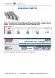
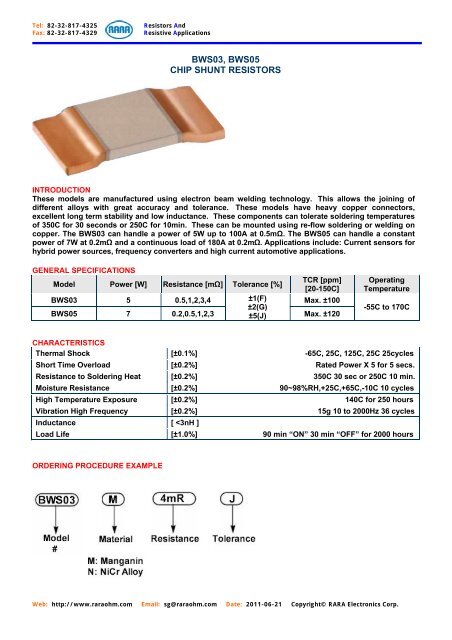
Tel: 82-32-817-4325Fax: 82-32-817-4329Resistors AndResistive ApplicationsBWS03, BWS05CHIP SHUNT RESISTORSINTRODUCTIONThese models are manufactured using electron beam welding technology. This allows the joining ofdifferent alloys with great accuracy and tolerance. These models have heavy copper connectors,excellent long term stability and low inductance. These components can tolerate soldering temperaturesof 350C for 30 seconds or 250C for 10min. These can be mounted using re-flow soldering or welding oncopper. The BWS03 can handle a power of 5W up to 100A at 0.5mΩ. The BWS05 can handle a constantpower of 7W at 0.2mΩ and a continuous load of 180A at 0.2mΩ. Applications include: Current sensors forhybrid power sources, frequency converters and high current automotive applications.GENERAL SPECIFICATIONSTCR [ppm]Model Power [W] Resistance [mΩ] Tolerance [%][20-150C]BWS03 5 0.5,1,2,3,4 ±1(F) Max. ±100±2(G)BWS05 7 0.2,0.5,1,2,3 ±5(J) Max. ±120OperatingTemperature-55C to 170CCHARACTERISTICSThermal Shock [±0.1%] -65C, 25C, 125C, 25C 25cyclesShort Time Overload [±0.2%] Rated Power X 5 for 5 secs.Resistance to Soldering Heat [±0.2%] 350C 30 sec or 250C 10 min.Moisture Resistance [±0.2%] 90~98%RH,+25C,+65C,-10C 10 cyclesHigh Temperature Exposure [±0.2%] 140C for 250 hoursVibration High Frequency [±0.2%] 15g 10 to 2000Hz 36 cyclesInductance [
Tel: 82-32-817-4325Fax: 82-32-817-4329Resistors AndResistive ApplicationsDIMENSIONS AND MATERIALSModel Value Material Thickness(t)BWS03-M 0.5mΩ Manganin 0.88mm+/-0.05BWS03-M 1mΩ Manganin 0.43mm+/-0.05BWS03-N 2mΩ NiCr Alloy 0.64mm+/-0.05BWS03-N 3mΩ NiCr Alloy 0.43mm+/-0.05BWS03-N 4mΩ NiCr Alloy 0.32mm+/-0.05BWS05-M 0.2mΩ Manganin 1.5mm±0.05BWS05-M 0.5mΩ Manganin 0/56mm+/-0.05BWS05-N 1mΩ NiCr Alloy 0.90mm+/-0.05BWS05-N 2mΩ NiCr Alloy 0.45mm+/-0.05BWS05-N 3mΩ NiCr Alloy 0.30mm+/-0.05RATED POWER DEPENDENCE OF RESISTANCE VALUEModelResistanceTCRPowerThicknessValue[mΩ](20C & 150C)[W]BWS03M 0.5 0.88 ±75ppm/C 5BWS03M 1 0.43 ±60ppm/C 4BWS03N 2 0.64 ±100ppm/C 4BWS03N 3 0.43 ±100ppm/C 3BWS03N 4 0.32 ±100ppm/C 2.5ModelResistanceTCRPowerThicknessValue[mΩ](20C & 150C)[W]BWS05M 0.2 1.5 ±100ppm/C 7BWS05M 0.5 0.56 ±100ppm/C 6BWS05N 1 0.9 ±120ppm/C 6BWS05N 2 0.45 ±120ppm/C 4BWS05N 3 0.3 ±120ppm/C 3.5Web: http://www.raraohm.com Email: sg@raraohm.com Date: 2011-06-21 Copyright© <strong>RARA</strong> <strong>Electronics</strong> Corp.
Tel: 82-32-817-4325Fax: 82-32-817-4329Resistors AndResistive ApplicationsDERATING CURVESTHEORETICAL PCB LAYOUTWeb: http://www.raraohm.com Email: sg@raraohm.com Date: 2011-06-21 Copyright© <strong>RARA</strong> <strong>Electronics</strong> Corp.
Tel: 82-32-817-4325Fax: 82-32-817-4329Resistors AndResistive ApplicationsPULSE ENERGY/PULSE POWER FOR CONTINOUS OPERATIONThis max. curve is only valid for the resistance value 0.5m. The min. curve is only valid for the resistancevalue of 4m. For other resistance values the area in between the max. and the min. curve is validThis max. curve is only valid for the resistance value 0.2m. The min. curve is only valid for the resistancevalue 2m. For other resistance values the area in between the max. and the min. curve is validWeb: http://www.raraohm.com Email: sg@raraohm.com Date: 2011-06-21 Copyright© <strong>RARA</strong> <strong>Electronics</strong> Corp.